How to mount and wire Tapo Outdoor Pan/Tilt Security Floodlight Camera
Introduction
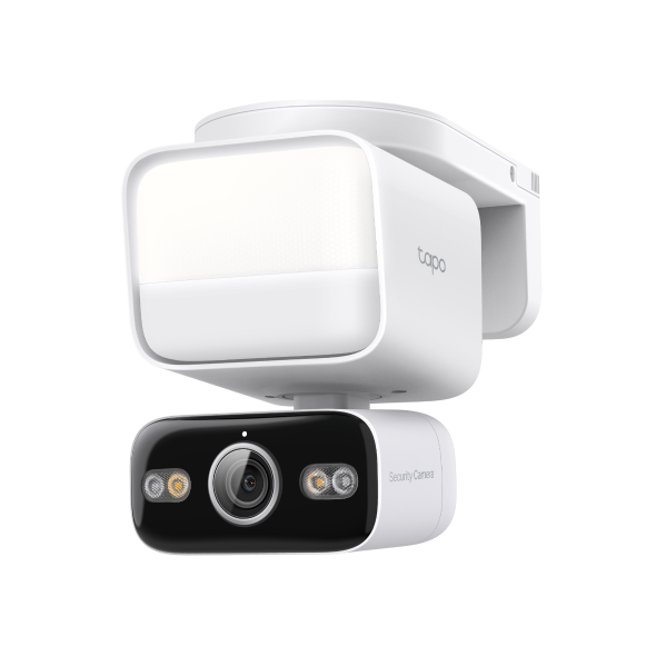
This article provides step-by-step wiring and installation guidance for the pan/tilt floodlight camera.
Requirements
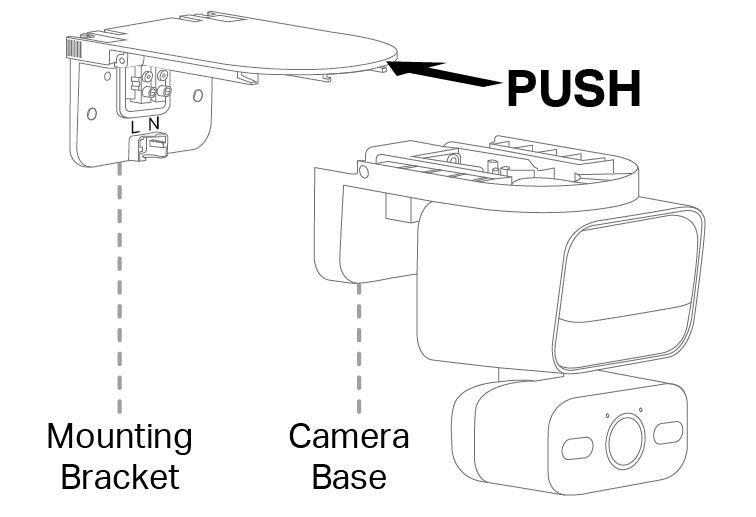
---Preparation: Separate the mounting bracket from the floodlight camera base for wiring.
---Before You Start: WARNING: Risk of Electric Shocks
- To avoid the risk of electric shock, injury, or death, exercise caution at all times. Hire a professional licensed electrician if necessary.
- Disconnect power at the fuse or circuit breaker before installing.
- Verify that the power supply voltage is correct. Connect fixture to a 100-240 VAC 50/60 Hz power source.
- Always follow code standards when installing wired connections.
- Install only on a UL-listed junction box or a wall with a Neutral wire and a Line wire.
- An all-pole mains switch shall be incorporated in the electrical installation of the building. The contact separation of the switch shall not be less than 3 mm.
- You can always find detailed wiring and mounting instructions in the Tapo app.

NOTICE
- Do not install near combustible or flammable surfaces.
- Do not connect this light fixture to a dimmer switch or timer.
Installation
- Wire colors vary by region. If you are unfamiliar with basic electrical wiring, please consult a licensed electrician.
- The outer diameter of the AC wires should be 2.4-3.1 mm (0.09-0.12 in.). Securely connect wires to the power compartment to ensure waterproof performance.
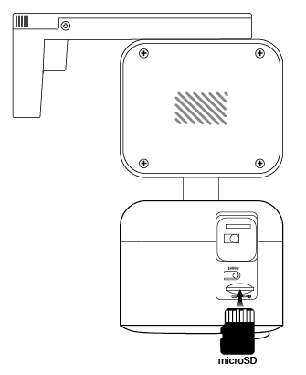
- You can insert a microSD card for local recording before installation.
- Do not place the camera upside down.
- For optimal detection performance and lighting range:
1) We recommend mounting the floodlight camera 2-3 m (7-10 ft) above the ground.
2) Ensure the floodlight camera is placed on a flat surface and installed parallel to the wall.
The floodlight camera can be mounted on a junction box on a wall.
Step 1: Turn off the circuit breaker. Make sure the power is off by turning your light on and off a few times.

Step 2: Remove the existing floodlight camera and disconnect wires from the junction box.
Step 3: Select a pair of plate screws that match the screw hole size in your junction box. Install the mounting plate on the junction box.
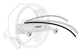
Step 4: Cover the Ground wire (usually green/green and yellow) with a wire connector or insulating tape (not included) and hide it in the junction box. If there is no Ground wire, skip this step.
Note: To identify wire colors, you can refer to https://www.tp-link.com/support/faq/3474/
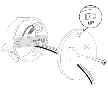
Step 5: Route the Neutral and Line wires through the rectangular hole on the box cover. Attach the box cover to the junction box and secure it with the cover screw.
Note: Ensure UP on the box cover points up. To install horizontally, adjust the cover to ensure the air bubble in the level is centered.
Step 6: Route the wires through the rectangular hole on the mounting bracket. Align the snap-fit, slide the bracket onto the cover, and secure it with two bracket screws.
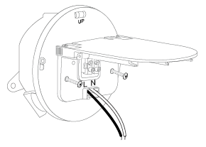
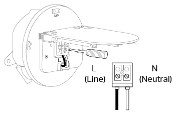
Step 7: Insert the Line and Neutral wires (recommended strip length: 10-13 mm [0.4-0.5 in.]) fully into the silicone holes until they reach the bracket terminals. Secure the wires with a slotted screwdriver.
Note: Do not expose stripped wires outside the waterproof silicone holes. When the wires are too short, stiff, or soft to connect, you can refer to https://www.tp-link.com/support/faq/3883/
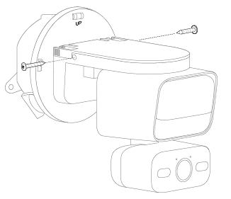
Step 8: Hide the wires in the camera base. Slide the camera onto the bracket until it clicks into place, then secure it with two camera screws.
Step 9: Turn on the circuit breaker. Wait until the System LED blinks red and green for setup.
Install where the Neutral wire and Line wire are available on a wall.
Step 1: Turn off the circuit breaker. Make sure the power is off by turning your light on and off a few times.
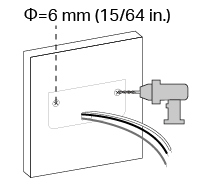
Step 2: Route the wires through the rectangular hole on the mounting template sticker and place the sticker. Drill two holes where indicated.
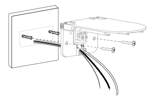
Step 3: Insert two mounting anchors into the holes. Route the wires through the rectangular hole on the mounting bracket. Use the mounting screws to affix the bracket over the anchors.
Step 4: Cover the Ground wire (usually green/green and yellow) with a wire connector or insulating tape (not included). If there is no Ground wire, skip this step.
Note: To identify wire colors, you can refer to https://www.tp-link.com/support/faq/3474/
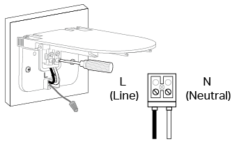
Step 5: Insert the Line and Neutral wires (recommended strip length: 10-13 mm [0.4-0.5 in.]) fully into the silicone holes until they reach the bracket terminals. Secure the wires with a slotted screwdriver.
Note: Do not expose stripped wires outside the waterproof silicone holes. When the wires are too short, stiff, or soft to connect, you can refer to https://www.tp-link.com/support/faq/3883/
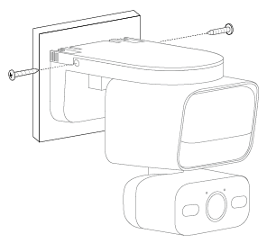
Step 6: Hide the wires in the camera base. Slide the camera onto the bracket until it clicks into place, then secure it with two camera screws.
Step 7: Turn on the circuit breaker. Wait until the System LED blinks red and green for setup.
Get to know more details of each function and configuration please go to Download Center to download the manual of your product.
Is this faq useful?
Your feedback helps improve this site.
TP-Link Community
Still need help? Search for answers, ask questions, and get help from TP-Link experts and other users around the world.