Table of Contents
TL-WA1201 4.0 Installation and User Guide
About This Guide
This guide is a complement of Quick Installation Guide. The Quick Installation Guide instructs you on quick internet setup, and this guide provides details of each function and shows you the way to configure these functions appropriate to your needs.
Note: Features available in the device may vary by model and software version. Device availability may also vary by region or ISP. All images, steps, and descriptions in this guide are only examples and may not reflect your actual experience.
Conventions
In this guide the following conventions are used:
|
Convention |
Description |
|---|---|
|
Underline |
Underlined words or phrases are hyperlinks. You can click to redirect to a website or a specific section. |
|
Bold |
Contents to be emphasized and texts on the web page are in bold, including the menus, items, buttons and so on. |
|
> |
The menu structures to show the path to load the corresponding page. For example, Settings > System Tools > Firmware Upgrade means the Firmware Upgrade page is under the System Tools menu that is located in the Settings tab. |
|
Note: |
Ignoring this type of note might result in a malfunction or damage to the device. |
|
Tip: |
Indicates important information that helps you make better use of your device. |
More Info
The latest software, management app and utility can be found at Download Center at https://www.tp-link.com/support/download.
The Quick Installation Guide can be found where you find this guide or inside the package.
Specifications can be found on the product page at https://www.tp-link.com.
TP-Link Community is provided for you to discuss our products and share knowledge at https://community.tp-link.com.
Our Technical Support contact information can be found at the Contact Technical Support page at https://www.tp-link.com/support.
Get to Know About Your Access Point
This chapter introduces what the Access Point can do and its appearance.
It contains the following sections:
- Product Overview
- Appearance
1. Product Overview
The TP-Link access point, with multiple operation modes, is designed to establish or expand a scalable high-speed wireless network or to connect your Ethernet enabled device to a wireless network, such as the game console, digital media adapter, printer, or network attached storage device. The access point supports a host of different functions that make your wireless networking experience more flexible than ever before. Now, you can enjoy a better internet experience when downloading, gaming, video streaming or with any other application that you may wish to use.
2. Appearance
Front Panel

LED Explanation
You can check the Access Point’s working status by following the LED Explanation table.
|
Name |
Status |
Indication |
|
(Power) |
On |
Power is on. |
|
Blinking once every |
The system is starting up or the firmware upgrade is in progress. Do not disconnect or power off your access point. |
|
|
Blinking twice every second |
WPS connection is in progress. This may take up to 2 minutes. |
|
|
Off |
Power is off. |
|
|
(Ethernet) |
On |
The Ethernet port is connected to a powered-on device. |
|
Off |
The Ethernet port is not connected to a powered-on device. |
|
|
(2.4GHz Wireless) |
On |
The 2.4GHz wireless band is enabled. |
|
Off |
The 2.4GHz wireless band is disabled. |
|
|
(5GHz Wireless) |
On |
The 5GHz wireless band is enabled. |
|
Off |
The 5GHz wireless band is disabled. |


Back Panel
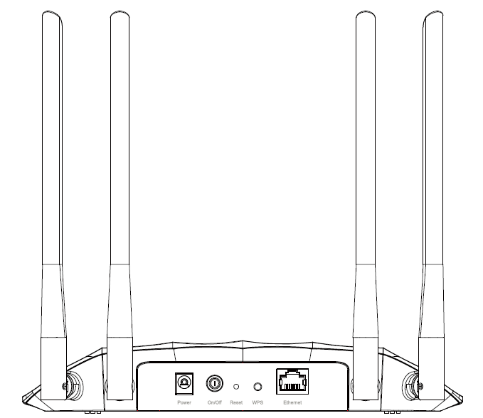
Button and Port Description
|
Button and Port |
Description |
|
Power Port |
For connecting the access point to a power socket via the provided power adapter. |
|
On/Off Button |
Press this button to power on or off the access point. |
|
Reset |
Press and hold this button until the Power LED blinks to reset the access point to its factory default settings. |
|
WPS |
Press this button and immediately press the WPS button on another device to quickly establish a wireless connection. |
|
Ethernet Port |
For connecting an Ethernet enabled device, such as a router or desktop. |
|
Antennas |
Used for wireless operation and data transmitting. Upright them for the best Wi-Fi performance. |
• The product should not be located in a place where it will be exposed to moisture or excessive heat.
• Place the access point in a location where it can be connected to various devices as well as to a power source.
• Make sure the cables and power cord are safely placed out of the way so they do not create a tripping hazard.
• The access point can be placed on a shelf or desktop.
• Keep the access point away from devices with strong electromagnetic interference, such as Bluetooth devices, cordless phones and microwaves.
FAQ
How do I restore the access point to its factory default settings?
With the access point powered on, use a pin to press and hold the Reset button until the Power LED starts blinking, then release the button.
Note: Resetting the access point will clear all previous configurations, and the access point will reset to the default Access Point mode.
What should I do to maximize my signal strength in Range Extender mode?
When choosing an ideal location to optimize wireless signal in Range Extender mode, please refer to the following recommendations.
• Halfway is the best way.
Generally, the ideal location for a repeater is about halfway between your wireless router and your wireless clients and make sure that the location you choose is within
the range of the host router. If that is not possible, place it closer to your wireless router to ensure stable performance.
• Fewer obstacles ensure better performance.
Choose a location with less obstacles around that may block the signal between the access point and the host network. An open corridor or a spacious location is ideal.
• Less interference provides more stability.
Choose a location away from Bluetooth devices and other household electronics, such as cordless phones, microwaves, and baby monitors to minimize signal interference.
Authentication
FCC compliance information statement

Product Name: AC1200 Wireless Gigabit Access Point
Model Number: TL-WA1201
| Component Name | Manufacturor | Model |
|---|---|---|
| I.T.E. Power Supply | TP-Link |
T120150-2B1 |
Responsible party:
TP-Link Systems Inc.
Address: 10 Mauchly, Irvine, CA 92618
Website: http://www.tp-link.com/us/
Tel: +1 626 333 0234
Fax: +1 909 527 6804
E-mail: sales.usa@tp-link.com
This equipment has been tested and found to comply with the limits for a Class B digital device, pursuant to part 15 of the FCC Rules. These limits are designed to provide reasonable protection against harmful interference in a residential installation. This equipment generates, uses and can radiate radio frequency energy and, if not installed and used in accordance with the instructions, may cause harmful interference to radio communications. However, there is no guarantee that interference will not occur in a particular installation. If this equipment does cause harmful interference to radio or television reception, which can be determined by turning the equipment off and on, the user is encouraged to try to correct the interference by one or more of the following measures:
• Reorient or relocate the receiving antenna.
• Increase the separation between the equipment and receiver.
• Connect the equipment into an outlet on a circuit different from that to which the receiver is connected.
• Consult the dealer or an experienced radio/ TV technician for help.
This device complies with part 15 of the FCC Rules. Operation is subject to the following two conditions:
1. This device may not cause harmful interference.
2. This device must accept any interference received, including interference that may cause undesired operation.
Any changes or modifications not expressly approved by the party responsible for compliance could void the user’s authority to operate the equipment.
Note: The manufacturer is not responsible for any radio or TV interference caused by unauthorized modifications to this equipment. Such modifications could void the user’s authority to operate the equipment.
FCC RF Radiation Exposure Statement
This equipment complies with FCC RF radiation exposure limits set forth for an uncontrolled environment. This device and its antenna must not be co-located or operating in conjunction with any other antenna or transmitter.
To comply with FCC RF exposure compliance requirements, this grant is applicable to only Mobile Configurations. The antennas used for this transmitter must be installed to provide a separation distance of at least 20 cm from all persons and must not be co-located or operating in conjunction with any other antenna or transmitter.
We, TP-Link Systems Inc., has determined that the equipment shown as above has been shown to comply with the applicable technical standards, FCC part 15. There is no unauthorized change is made in the equipment and the equipment is properly maintained and operated.
Issue Date: 2025-09-29
FCC compliance information statement
Product Name: I.T.E. Power Supply
Model Number: T120150-2B1
Responsible party:
TP-Link Systems Inc.
Address: 10 Mauchly, Irvine, CA 92618
Website: http://www.tp-link.com/us/
Tel: +1 626 333 0234
Fax: +1 909 527 6804
E-mail: sales.usa@tp-link.com
This equipment has been tested and found to comply with the limits for a Class B digital device, pursuant to part 15 of the FCC Rules. These limits are designed to provide reasonable protection against harmful interference in a residential installation. This equipment generates, uses and can radiate radio frequency energy and, if not installed and used in accordance with the instructions, may cause harmful interference to radio communications. However, there is no guarantee that interference will not occur in a particular installation. If this equipment does cause harmful interference to radio or television reception, which can be determined by turning the equipment off and on, the user is encouraged to try to correct the interference by one or more of the following measures:
• Reorient or relocate the receiving antenna.
• Increase the separation between the equipment and receiver.
• Connect the equipment into an outlet on a circuit different from that to which the receiver is connected.
• Consult the dealer or an experienced radio/ TV technician for help.
This device complies with part 15 of the FCC Rules. Operation is subject to the following two conditions:
1.This device may not cause harmful interference.
2.This device must accept any interference received, including interference that may cause undesired operation.
Any changes or modifications not expressly approved by the party responsible for compliance could void the user’s authority to operate the equipment.
We, TP-Link Systems Inc., has determined that the equipment shown as above has been shown to comply with the applicable technical standards, FCC part 15. There is no unauthorized change is made in the equipment and the equipment is properly maintained and operated.
Issue Date: 2025-09-29
CE Mark Warning

OPERATING FREQUENCY(the maximum transmitted power)
2400 MHz -2483.5 MHz (20dBm)
5150 MHz -5250 MHz (23dBm)
EU Declaration of Conformity
TP-Link hereby declares that the device is in compliance with the essential requirements and other relevant provisions of directives 2014/53/EU, 2009/125/EC, 2011/65/EU and (EU)2015/863.
The original EU Declaration of Conformity may be found at https://www.tp-link.com/en/support/ce/
RF Exposure Information
This device meets the EU requirements (2014/53/EU Article 3.1a) on the limitation of exposure of the general public to electromagnetic fields by way of health protection.
The device complies with RF specifications when the device used at 20 cm from your body.
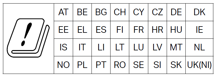
National Restrictions
Frequency band: 5150 - 5250 MHz:
Indoor use: Inside buildings only. Installations and use inside road vehicles and train carriages are not permitted. Limited outdoor use: If used outdoors, equipment shall not be attached to a fixed installation or to the external body of road vehicles, a fixed infrastructure or a fixed outdoor antenna. Use by unmanned aircraft systems (UAS) is limited to within the 5170 - 5250 MHz band.
UKCA Mark

UK Declaration of Conformity
TP-Link hereby declares that the device is in compliance with the essential requirements and other relevant provisions of the Radio Equipment Regulations 2017.
The original UK Declaration of Conformity may be found at https://www.tp-link.com/support/ukca
National Restrictions
Attention: This device may only be used indoors in Great Britain.
Korea Warning Statements
당해 무선설비는 운용중 전파혼신 가능성이 있음.

Продукт сертифицировано згідно с правилами системи УкрСЕПРО на відповідність вимогам нормативних>Продукт сертифіковано згідно с правилами системи УкрСЕПРО на відповідність вимогам нормативних документів та вимогам, що передбачені чинними законодавчими актами України.

Safety Information
Keep the device away from water, fire, humidity or hot environments.
Do not attempt to disassemble, repair, or modify the device. If you need service, please contact us.
Do not use damaged charger or USB cable to charge the device.
Do not use any other chargers than those recommended.
Do not use the device where wireless devices are not allowed.
Adapter shall be installed near the equipment and shall be easily accessible.
Use only power supplies which are provided by manufacturer and in the original packing of this product. If you have any questions, please don’t hesitate to contact us.
Operating Temperature: 0℃ ~ 40℃ (32℉ ~ 104℉)
This product uses radios and other components that emit electromagnetic fields. Electromagnetic fields and magnets may interfere with pacemakers and other implanted medical devices. Always keep the product and its power adapter more than 15 cm (6 inches) away from any pacemakers or other implanted medical devices. If you suspect your product is interfering with your pacemaker or any other implanted medical device, turn off your product and consult your physician for information specific to your medical device.
Please read and follow the above safety information when operating the device. We cannot guarantee that no accidents or damage will occur due to improper use of the device. Please use this product with care and operate at your own risk.
Explanation of the symbols on the product label
Note: The product label is on the bottom of the product and its power supply. Symbols may vary from products.
注意:產品標籤可以在產品底部和其I.T.E.電源供應器上找到。符號可能因產品而異。
| Symbol 符號解釋 |
Explanation 解釋 |
|---|---|
 |
Class II equipment Class II 設備 |
 |
Class II equipment with functional earthing 具有功能接地的Class II 設備 |
 |
Alternating current 交流電 |
 |
DC voltage 直流電壓 |
 |
Polarity of output terminals 輸出端子極性 |
 |
Indoor use only 僅限室內使用 |
 |
Dangerous voltage 危險電壓 |
 |
Caution, risk of electric shock 注意,有觸電危險 |
 |
Energy efficiency Marking 能源效率標示 |
 |
Protective earth 保護接地 |
 |
Earth 接地 |
 |
Frame or chassis 機架接地 |
 |
Functional earthing 功能接地 |
 |
Caution, hot surface 警告,表面高溫 |
 |
Caution 警告 |
 |
Operator’s manual 操作手冊 |
 |
Stand-by 待機 |
 |
“ON”/”OFF” (push-push) 「開」/「關」 ( 按壓式) |
 |
Fuse 保險絲 |
 |
Fuse is used in neutral N 保險絲用於中性線N |
 |
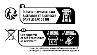
RECYCLING This product bears the selective sorting symbol for Waste electrical and electronic equipment (WEEE). This means that this product must be handled pursuant to European directive 2012/19/EU in order to be recycled or dismantled to minimize its impact on the environment. User has the choice to give his product to a competent recycling organization or to the retailer when he buys a new electrical or electronic equipment. 回收利用 本產品標示有「廢棄電氣電子設備(WEEE)」的分類回收標誌。這表示本產品必須依據歐盟指令 2012/19/EU 進行妥善回收或拆 解,以減少對環境的影響。 使用者可選擇將本產品交給合格的回收機構,或在購買新電器或電子設備時,交回給零售商進行回收處理。 |
 |
Caution, avoid listening at high volume levels for long periods 注意,避免長時間以高音量收聽 |
 |
Disconnection, all power plugs 斷開所有電源插頭 |
| m | Switch of mini-gap construction 微間隙結構的開關 |
| µ | Switch of micro-gap construction (for US version) Switch of micro-gap / micro-disconnection construction (for other versions except US) 微小間隙結構開關(適用於美國版) 微小間隙 / 微小斷開結構開關(適用於美國以外的其他版本) |
| ε | Switch without contact gap (Semiconductor switching device) 無接點間隙開關(半導體開關裝置) |
Use only power supplies listed in the user instructions:
| Component Name | Manufacturor | Model |
|---|---|---|
| I.T.E. Power Supply | TP-Link |
T120150-2B1 (US) T120100-2C1 (EU) T120100-2D1 (UK) |