Omada SDN Controller User Guide
- About this Guide
- Chapter 1 Omada SDN Controller Solution Overview
- Chapter 2 Get Started with Omada SDN Controller
- Chapter 3 Manage Omada Managed Devices and Sites
- Chapter 4 Configure the Network with Omada SDN Controller
- Chapter 5 Configure the Omada SDN Controller
- Chapter 6 Configure and Monitor Omada Managed Devices
- Chapter 7 Monitor and Manage the Clients
- Chapter 8 Monitor the network
- Chapter 9 Manage Administrator Accounts of Omada SDN Controller
- Chapter 10 Omada APP
6. Configure and Monitor Omada Managed Devices
This chapter guides you on how to configure and monitor Omada managed devices, including gateways, switches and EAPs. You can configure the devices individually or in batches to modify the configurations of certain devices. The chapter includes the following sections:
�? 6. 1 Introduction to the Devices Page
�? 6. 2 Configure and Monitor the Gateway
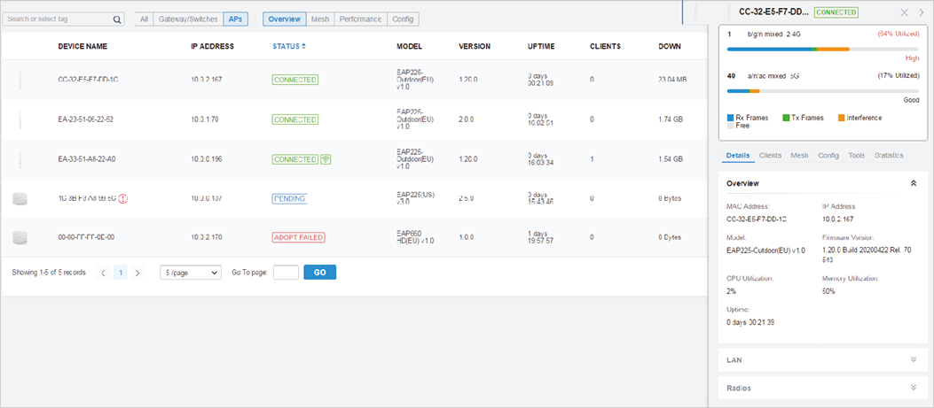
6. 1 Introduction to the Devices Page
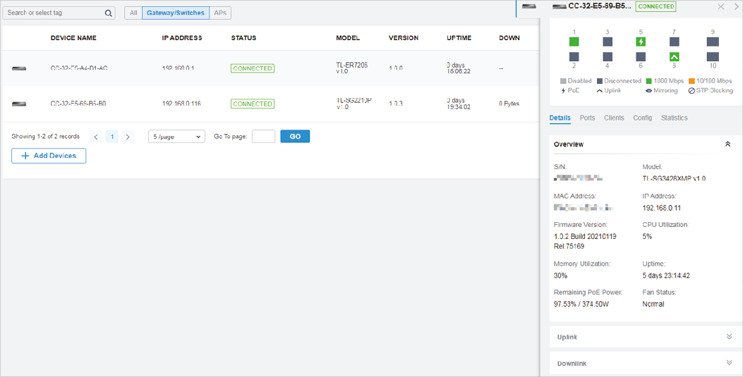
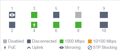
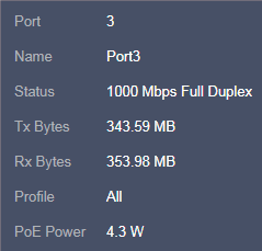
The Devices page displays all TP-Link devices discovered by the controller and their general information.
For an easy monitoring of the devices, you can customize the column and filter the devices for a better overview of device information. Also, quick operations and Batch Edit are available for configurations.
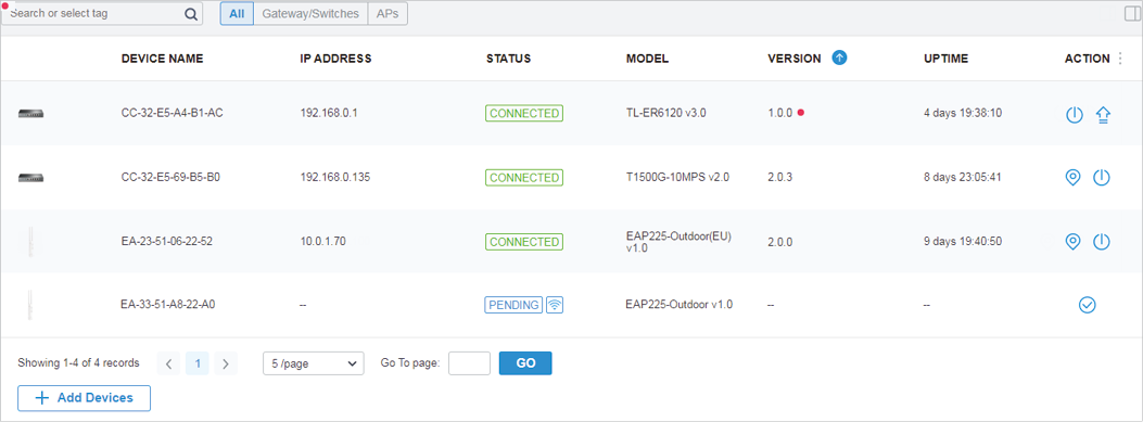
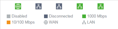
According the connection status, the devices have the following status: Pending, Isolated, Connected, Managed by Others, Heartbeat Missed, and Disconnected. The icons in the Status column are explained as follows:
|
|
, and the controller will use the default username and password to adopt it. When adopting, its status will change from Adopting, Provisioning, Configuring, to Connected eventually. | ||||
|
|
Mesh . |
||||
|
|
|
|
|
|
Once connected to the controller, the device will send inform packets to the controller in a regular interval to maintain the connection. If the controller does not receive its inform packets in 30 seconds, the device will turn into the Heartbeat Missed status. For a heartbeat-missed device, if the controller receives an inform packet from the device in 5 minutes, its status will become Connected again; otherwise, its status will become Disconnected. |
|
|
|
|
Mesh . |
||
|
|
�? Customize the Column
To customize the columns, click
![]() next to
Action
and check the boxes of information type.
next to
Action
and check the boxes of information type.
To change the list order, click the column head and
![]() will appear to indicate the ascending or descending order.
will appear to indicate the ascending or descending order.
�? Filter the Devices
Use the search box and tab bar above the table to filter the devices.
To search the devices, enter the text in the search box or select a tag from the drop-down list. As for the device tag, refer to the general configuration of switches and EAPs .
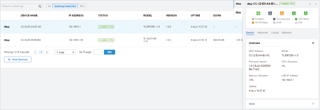
To filter the devices, a tab bar
 is above the table to filter the devices by device type.
If you select the
APs
tab, another tab bar
 will be available to change the column quickly.
|
Overview |
|
Mesh |
|
Performance |
|
Config |
�? Quick Operations Click the icons in Header or the Action column to quickly adopt, locate, upgrade, or reboot the device.
�? Batch Edit (for Switches and EAPs) After selecting the Gateway/Switches or APs tab, you can adopt or configure the switches or EAPs in batches. Batch Config is available only for the devices in Connected/Disconnected/Heartbeat Missed/Isolated status, while Batch Adopt is available for the devices in the Pending/Managed By Others status. Click Batch Action. select Batch Adopt , click the checkboxes of devices, and click Done . If the selected devices are all in the Pending status, the controller will adopt then with the default username and password. If not, enter the username and password manually to adopt the devices. Click Batch Action , select Batch Config , click the checkboxes of devices, and click Done . Then the Properties window appears. There are two tabs in the window: Devices and Config.
In Devices, you can click
In Config, all settings are Keep Existing by default. For detailed configurations, refer to the configuration of switches and EAPs .
|


 .
.


 Configuration Guidelines:
 to delete them.
 in the controller. Click
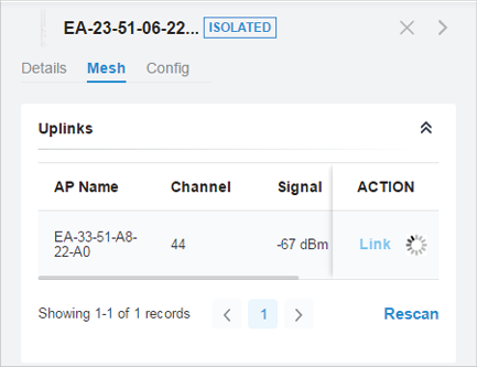
 to adopt the EAP in Pending (Wireless) status in the
 within your controller.
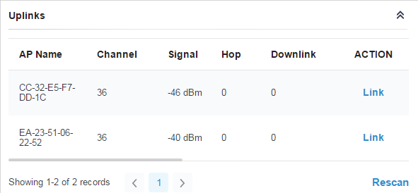
 to connect the Uplink AP in the