Omada SDN Controller User Guide
- About this Guide
- Chapter 1 Omada SDN Controller Solution Overview
- Chapter 2 Get Started with Omada SDN Controller
- Chapter 3 Manage Omada Managed Devices and Sites
- Chapter 4 Configure the Network with Omada SDN Controller
- Chapter 5 Configure the Omada SDN Controller
- Chapter 6 Configure and Monitor Omada Managed Devices
- Chapter 7 Monitor and Manage the Clients
- Chapter 8 Monitor the network
- Chapter 9 Manage Administrator Accounts of Omada SDN Controller
- Chapter 10 Omada APP
4. Configure the Network with Omada SDN Controller
This chapter guides you on how to configure the network with Omada SDN Controller. As the command center and management platform at the heart of the Omada network, Omada SDN Controller provides a unified approach to configuring enterprise networks comprised of routers, switches, and wireless access points. The chapter includes the following sections:
�? 4. 2 Modify the Current Site Configuration
�? 4. 3 Configure Wired Networks
As you start using the management interface of the controller (Controller UI) to configure and monitor your network, it is helpful to familiarize yourself with the most commonly-used elements of the Controller UI that are frequently referenced in this guide.
The Controller UI is grouped into task-oriented menus, which are located in the top right-hand corner and the left-hand navigation bar of the page. Note that the settings and features that appear in the UI depend on your user account permissions. The following image depicts the main elements of the Controller UI.
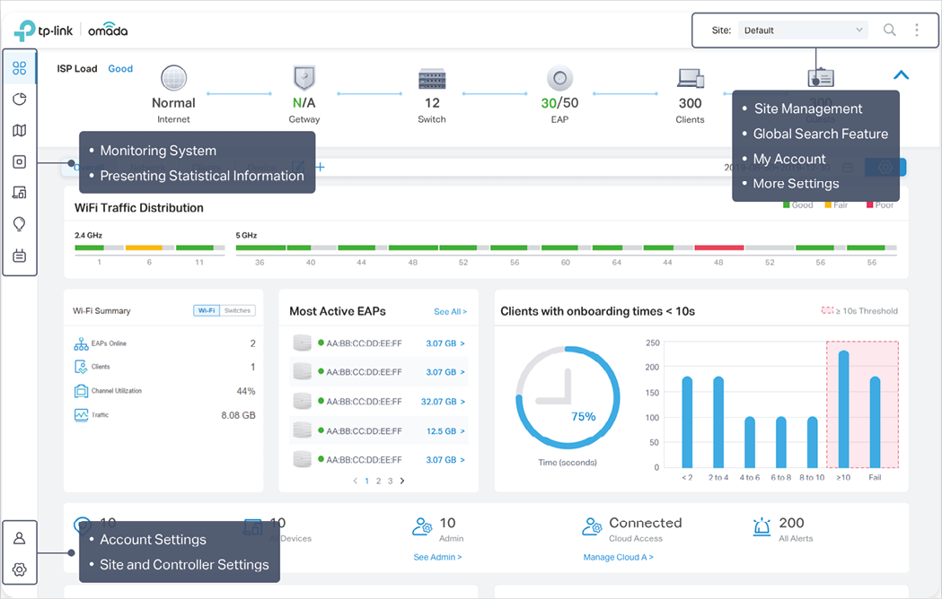
The elements in the top right corner of the screen give quick access to:
|
|
|
Site Management Site Manager �? have a quick overview of sites, including the name, location, managed devices, and connected clients. Add New Site �? add a new site, which is the logically separated network location. The site is the largest unit for managing the network. Import Site �? import the site from another controller. |
|
Global Search Feature and enter the keywords to quickly look up the functions that you want to configure. And you can search for the devices by their MAC addresses and device names. |
|
My Account to display account information, Account Settings and Log Out. You can change your password on Account Settings. |
|
More Settings to display Preferences, About and Tutorial.Preferences : Click to jump to Maintenance and customize the Controller UI depending on your needs. For details, refer to 5. 3 Maintenance About : Click to display the controller version. Tutorial : Click to view the quick Getting Started guide which demonstrates the navigation and tools available for the controller. |

The left-hand navigation bar provides access to:

|
Dashboard displays a summarized view of the network status through different visualizations. The widget-driven dashboard is customizable depending on your needs. |
|
Statistics provides a visual representation of the clients and network managed by the controller. The run charts show changes in device performances over time, including the status of switches and speed test results. |
|
|
Map generates the system topology automatically and you can look over the provisioning status of devices. By clicking on each node, you can view the detailed information of each device. You can also upload images of your location for a visual representation of your network. |
|
|
Devices displays all TP-Link devices discovered on the site and their general information. This list view can change depending on your monitoring needs through customizing the columns. You can click any device on the list to reveal the Properties window for more detailed information of each device and provisioning individual configurations to the device. |
|
|
Clients displays a list view of wired and wireless clients that are connected to the network. This list view can change depending on your monitoring need through customizing the columns. You can click any clients on the list to reveal the Properties window for more detailed information of each client and provisioning individual configurations to the client. |
|
|
Insight displays a list of statistics of your network device, clients and services during a specified period. You can change the range of date in one-day increments. |
|
|
Log displays logs that record varied activities of users, devices, and systems events, such as administrative actions and abnormal device behaviors. You can also configure notifications to receive alert emails of certain activities. |
|
|
Admin allows you to configure multi-level administrative accounts with a hierarchy of permissions that can be configured to provide finely grained levels of access to the controller as required by your enterprise. |
|
|
Settings is divided to two parts: Site Settings and Controller Settings. In Site Settings, you can provision and configure all your network devices on the same site in minutes. In Controller Settings, you can maintain the controller system for best performance. |
4. 2 Modify the Current Site Configuration
You can view and modify the configurations of the current site in Site, including the basic site information, centrally-managed device features, and the device account. The features and device account configured here are applied to all devices on the site, so you can easily manage the devices centrally.
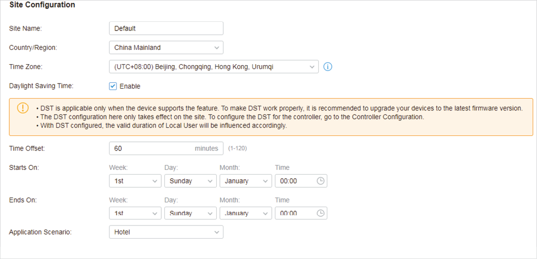
In Site Configuration, you can view and modify the site name, location, time zone, and application scenario of the current site.
Select a site from the drop down list of Sites in the top-right corner, go to Settings > Site , and configure the following information of the site in Site Configuration . Click Save .
|
Site Name |
|
Country/Region |
|
Time Zone |
|
Daylight Saving Time |
|
Time Offset |
|
Starts On |
|
Ends On |
|
Application Scenario |
Create New Scenario in the drop-down list. |
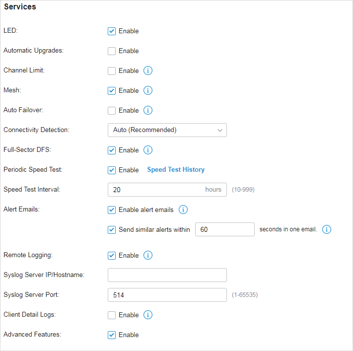
In Services, you can view and modify the features applied to devices on the current site. Most features are applied to all devices, such as LED, Automatic Upgrades, and Alert Emails, while some are applied to EAPs only, such as Channel Limit and Mesh.
Select a site from the drop down list of Sites in the top-right corner, go to Settings > Site , and configure the following features for the current site in Services . Click Save .
|
LED |
By default, the device follows the LED setting of the site it belongs to. To change the LED setting for certain devices, refer to Chapter 6. Configure and Monitor Omada Managed Devices . |
||||||
|
Automatic Upgrades |
|
Channel Limit |
|
|
Auto Failover |
To enable this feature, enable Mesh first. |
|
|
Connectivity Detection |
In a mesh network, the APs can send ARP request packets to a fixed IP address to test the connectivity. If the link fails, the status of these APs will change to Isolated. Auto (Recommended) : Select this method and the mesh APs will send ARP request packets to the default gateway for the detection. Custom IP Address : Select this method and specify a desired IP address. The mesh APs will send ARP request packets to the custom IP address to test the connectivity. If the IP address of the AP is in different network segments from the custom IP address, the AP will use the default gateway IP address for the detection. |
||||||
|
Full-Sector DFS |
To enable this feature, enable Mesh first. |
||||||
|
Periodic Speed Test |
Speed Test Interval : When enabled, specify the interval to decide how often to test the speed of devices. Speed Test History : Click it to view the history statistics of speed test in 8. 2. 3 Speed Test Statistics . |
||||||
|
Alert Emails |
Enable alert emails : When enabled, the controller can send emails to notify the administrators and viewers of the site’s alert logs once generated. Send similar alerts within seconds in one email : When enabled, the similar alerts generated in each time period are collected and sent to administrators and viewers in one email. refer to 8. 5. 3 Notifications . |
||||||
|
Remote Logging |
Syslog Server IP/Hostname : Enter the IP address or hostname of the log server. Syslog Server Port : Enter the port of the server. Client Detail Logs : With this feature enabled, the logs of clients will be sent to the syslog server. |
||||||
|
Advanced Features |
Advanced Features . When disabled, these features keep the default settings. 4. 2. 3 Advanced Features . |
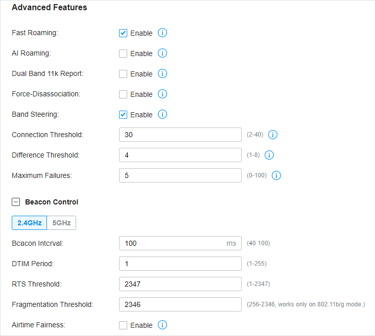
Advanced features include Fast Roaming, Band Steering, and Beacon Control, which are applicable to APs only. With these advanced features configured properly, you can improve the network’s stability, reliability and communication efficiency.
Advanced features are recommended to be configured by network administrators with the WLAN knowledge. If you are not sure about your network conditions and the potential impact of all settings, keep Advanced Features disabled in Services to use their default configurations.
Select a site from the drop down list of Sites in the top-right corner, go to Settings > Site , and enable Advanced Features in Services first. Then configure the following features in Advanced Features . Click Save .
|
Fast Roaming |
By default, it is disabled. This feature is available for some certain devices. |
||||||
|
AI Roaming |
|
Dual Band 11k Report |
When enabled, the controller provides neighbor list that contains neighbor APs in both 2.4 GHz and 5 GHz bands.
|
Force-Disassociation |
With this feature enabled, the AP will force disassociate the client if it does not re-associate to another AP.
|
Band Steering |
When enabled, dual-band clients will be steered to the 5 GHz band according to the configured parameters. With appropriate settings, Band Steering can improve the network performance because the 5 GHz band supports a larger number of non-overlapping channels and is less noisy. By default, it is disabled. Connection Threshold : Specify the maximum number of clients connected to the 5 GHz band. By default, the threshold is 30. Difference Threshold : Specify the maximum difference between the number of clients on the 5 GHz band and 2.4 GHz band. By default, the threshold is 4. Maximum Failures : Specify the maximum number of the failed attempts when a client repeatedly tries to associate with an EAP on 5 GHz. When the number of rejections reaches Maximum Failures, the EAP will accept the client’s request for connection. By default, it is 4. |
|
Beacon Control |
, select the band, and configure the following parameters of Beacon Control.
Beacon Interval : Specify how often the APs send a beacon to clients. By default, it is 100. DTIM Period : Specify how often the clients check for buffered data that are still on the EAP awaiting pickup. By default, the clients check for them at every beacon. RTS Threshold : RTS (Request to Send) can ensure efficient data transmission by avoiding the conflict of packets. If a client wants to send a packet larger than the threshold, the RTS mechanism will be activated to delay packets of other clients in the same wireless network. Fragmentation Threshold : Fragmentation can limit the size of packets transmitted over the network. If a packet to be sent exceeds the Fragmentation threshold, the Fragmentation function will be activated, and the packet will be fragmented into several packets. By default, the threshold is 2346. |
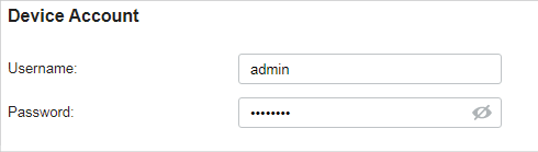
You can specify a device account for all adopted devices on the site in batches. Once the devices are adopted by the controller, their username and password become the same as settings in Device Account to protect the communication between the controller and devices. By default, the username is admin and the password is generated randomly.
Go to Settings > Site and modify the username and password in Device Account . Click Save and the new username and password are applied to all devices on the site.
Wired networks enable your wired devices and clients including the gateway, switches, EAPs and PCs to connect to each other and to the internet.
As shown in the following figure, Wired Networks consist of two parts: Internet and LAN.
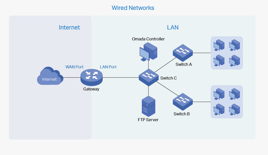
For Internet, you determine the number of WAN ports on the gateway and how they connect to the internet. You can set up an IPv4 connection and IPv6 connection to your internet service provider (ISP) according to your needs. The parameters of the internet connection for the gateway depends on which connection types you use. For an IPv4 connection, the following internet connection types are available: Dynamic IP, Static IP, PPPoE, L2TP, and PPTP. For an IPv6 connection, the following internet connection types are available: Dynamic IP (SLAAC/ DHCPv6), Static IP, PPPoE, 6to4 Tunnel, and Pass-Through (Bridge). And, when more than one WAN port is configured, you can configure Load Balancing to optimize the resource utilization if needed.
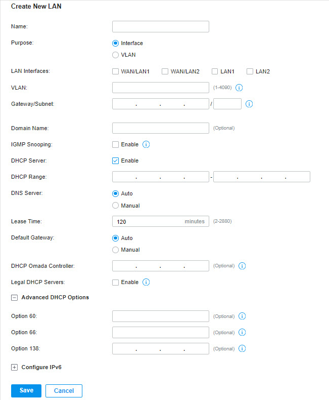
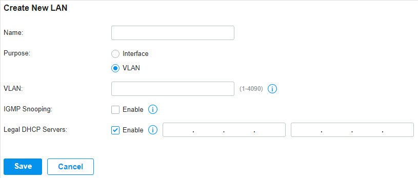
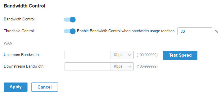
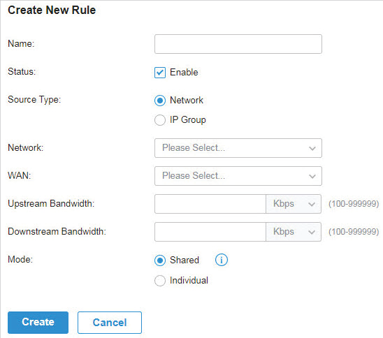
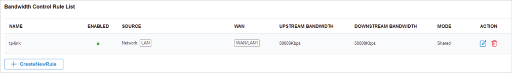
For LAN, you configure the wired internal network and how your devices logically separate from or connect to each other by means of VLANs and interfaces. Advanced LAN features include IGMP Snooping, DHCP Server and DHCP Options, PoE, Voice Network, 802.1X Control, Port Isolation, Spanning Tree, LLDP-MED, and Bandwidth Control.
4. 3. 1 Set Up an Internet Connection
To set up an internet connection, follow these steps:
1 ) Configure the number of WAN ports on the gateway based on needs.
2 ) Configure WAN Connections. You can set up the IPv4 connection, IPv6 connection, or both.
3 ) (Optional) Configure Load Balancing if more than one WAN port is configured.
|
Select WAN Mode |

|
Configure WAN Connections |

|
(Optional) Configure Load Balancing |
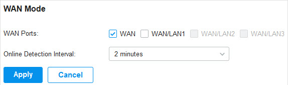
Go to Settings > Wired Networks > Internet to load the following page. In WAN Mode , configure the number of WAN ports deployed by the gateway and other parameters. Then click Apply .
|
WAN Ports |
|
Online Detection Interval |
Note that Load Balancing and Link Backup will take effects based on the results of online detection. Configure a proper online detection interval to make sure that Load Balancing and Link Backup works. |
|
Select WAN Mode |

|
Configure WAN Connections |

|
(Optional) Configure Load Balancing |
![]() Note:
Note:
|
The number of configurable WAN ports is decided by WAN Mode. |
�? Set Up IPv4 Connection
Go to Settings > Wired Networks > Internet . For WAN connections, choose a Connection Type according to the service provided by your ISP.
|
Connection Type |
Dynamic IP : If your ISP automatically assigns the IP address and the corresponding parameters, choose Dynamic IP. Static IP : If your ISP provides you with a fixed IP address and the corresponding parameters, choose Static IP. PPPoE : If your ISP provides you with a PPPoE account, choose PPPoE. L2TP : If your ISP provides you with an L2TP account, choose L2TP. PPTP : If your ISP provides you with a PPTP account, choose PPTP. |
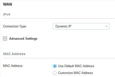
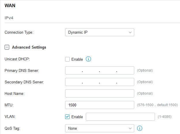
�? Dynamic IP
1. Choose Connection Type as Dynamic IP and configure the following parameters.
|
MAC Address |
Use Default MAC Address : The WAN port uses the default MAC address to set up the internet connection. It’s recommended to use the default MAC address unless required otherwise. Customize MAC Address : The WAN port uses a customized MAC address to set up the internet connection and you need to specify the MAC address. Typically, this is required when your ISP bound the MAC address with your account or IP address. If you are not sure, contact the ISP. |
2. Click + Advanced Settings and configure the following parameters. Then click Apply .
|
Unicast DHCP |
|
Primary DNS Server / Secondary DNS Server |
|
Host Name |
|
MTU |
MTU is the maximum data unit transmitted in the physical network. When the connection type is Dynamic IP, MTU can be set in the range of 576-1500 bytes. The default value is 1500. |
|
VLAN |
|
QoS Tag |
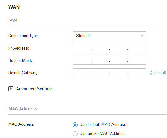
�? Static IP
1. Choose Connection Type as Static IP and configure the following parameters.
|
IP Address |
|
Subnet Mask |
|
Default Gateway |
|
MAC Address |
Use Default MAC Address : The WAN port uses the default MAC address to set up the internet connection. It’s recommended to use the default MAC address unless required otherwise. Customize MAC Address : The WAN port uses a customized MAC address to set up the internet connection and you need to specify the MAC address. Typically, this is required when your ISP bound the MAC address with your account or IP address. If you are not sure, contact the ISP. |
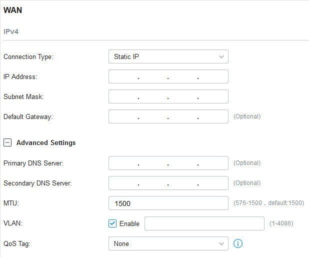
2. Click + Advanced Settings and configure the following parameters. Then click Apply .
|
Primary DNS Server / Secondary DNS Server |
|
MTU |
MTU is the maximum data unit transmitted in the physical network. When the connection type is Static IP, MTU can be set in the range of 576-1500 bytes. The default value is 1500. |
|
VLAN |
|
QoS Tag |
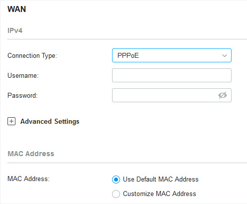
�? PPPoE
1. Choose Connection Type as PPPoE and configure the following parameters.
|
Username |
|
Password |
|
MAC Address |
Use Default MAC Address : The WAN port uses the default MAC address to set up the internet connection. It’s recommended to use the default MAC address unless required otherwise. Customize MAC Address : The WAN port uses a customized MAC address to set up the internet connection and you need to specify the MAC address. Typically, this is required when your ISP bound the MAC address with your account or IP address. If you are not sure, contact the ISP. |
2. Click + Advanced Settings and configure the following parameters. Then click Apply .
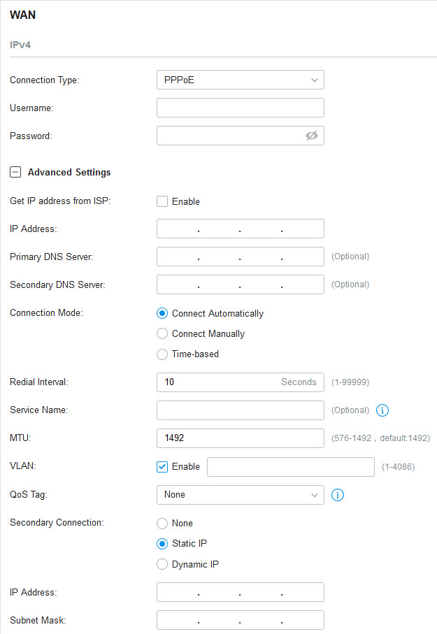
|
Get IP address from ISP |
With this option disabled, you need to specify the IP Address provided by your ISP. |
||
|
Primary DNS Server / Secondary DNS Server |
|
Connection Mode |
Connect Automatically : The gateway activates the connection automatically when the connection is down. You need to specify the Redial Interval , which decides how often the gateway tries to redial after the connection is down. Connect Manually : You can manually activate or terminate the connection. Time-Based : During the specified period, the gateway will automatically activate the connection. You need to specify the Time Range when the connection is up. |
|
Service Name |
|
MTU |
MTU is the maximum data unit transmitted in the physical network. When the connection type is PPPoE, MTU can be set in the range of 576-1492 bytes. The default value is 1492. |
|
VLAN |
|
QoS Tag |
|
|
Secondary Connection |
None : Select this if the secondary connection is not required by your ISP. Static IP : Select this if your ISP provides you with a fixed IP address and subnet mask for the secondary connection. You need to specify the IP Address and Subnet Mask provided by your ISP. Dynamic IP : Select this if your ISP automatically assigns the IP address and subnet mask for the secondary connection. |
�? L2TP
Choose Connection Type as L2TP and configure the following parameters. Then click Apply .
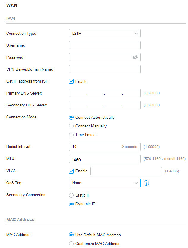
|
Username |
|
Password |
|
VPN Server / Domain Name |
|
Get IP address from ISP |
With this option disabled, you need to specify the IP address provided by your ISP. |
|
Primary DNS Server / Secondary DNS Server |
|
Connection Mode |
Connect Automatically : The gateway activates the connection automatically when the connection is down. You need to specify the Redial Interval , which decides how often the gateway tries to redial after the connection is down. Connect Manually : You can manually activate or terminate the connection. Time-Based : During the specified period, the gateway will automatically activate the connection. You need to specify the Time Range when the connection is up. |
||||
|
MTU |
MTU is the maximum data unit transmitted in the physical network. When the connection type is L2TP, MTU can be set in the range of 576-1460 bytes. The default value is 1460. |
||||||
|
VLAN |
|
QoS Tag |
|||||
|
Secondary Connection |
Static IP : Select this if your ISP provides you with a fixed IP address and subnet mask for the secondary connection. You need to specify the IP Address , Subnet Mask , Default Gateway (Optional) , Primary DNS Server (Optional) , and Secondary DNS Server (Optional) provided by your ISP. Dynamic IP : Select this if your ISP automatically assigns the IP address and subnet mask for the secondary connection. |
||||||
|
MAC Address |
Use Default MAC Address : The WAN port uses the default MAC address to set up the internet connection. It’s recommended to use the default MAC address unless required otherwise. Customize MAC Address : The WAN port uses a customized MAC address to set up the internet connection and you need to specify the MAC address. Typically, this is required when your ISP bound the MAC address with your account or IP address. If you are not sure, contact the ISP. |
�? PPTP
Choose Connection Type as PPTP and configure the following parameters. Then click Apply .
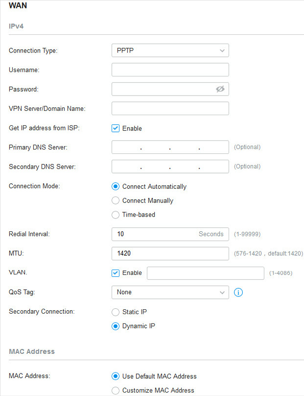
|
Username |
|
Password |
|
VPN Server / Domain Name |
|
Get IP address from ISP |
With this option disabled, you need to specify the IP address provided by your ISP. |
|
Primary DNS Server / Secondary DNS Server |
|
Connection Mode |
Connect Automatically : The gateway activates the connection automatically when the connection is down. You need to specify the Redial Interval , which decides how often the gateway tries to redial after the connection is down. Connect Manually : You can manually activate or terminate the connection. Time-Based : During the specified period, the gateway will automatically activate the connection. You need to specify the Time Range when the connection is up. |
||||
|
MTU |
MTU is the maximum data unit transmitted in the physical network. When the connection type is PPTP, MTU can be set in the range of 576-1420 bytes. The default value is 1420. |
||||||
|
VLAN |
|
QoS Tag |
|||||
|
Secondary Connection |
Static IP : Select this if your ISP provides you with a fixed IP address and subnet mask for the secondary connection. You need to specify the IP Address , Subnet Mask , Default Gateway (Optional) , Primary DNS Server (Optional) , and Secondary DNS Server (Optional) provided by your ISP. Dynamic IP : Select this if your ISP automatically assigns the IP address and subnet mask for the secondary connection. |
||||||
|
MAC Address |
Use Default MAC Address : The WAN port uses the default MAC address to set up the internet connection. It’s recommended to use the default MAC address unless required otherwise. Customize MAC Address : The WAN port uses a customized MAC address to set up the internet connection and you need to specify the MAC address. Typically, this is required when your ISP bound the MAC address with your account or IP address. If you are not sure, contact the ISP. |
�? Set Up IPv6 Connection
For IPv6 connections, check the box to enable the IPv6 connection, select the internet connection type according to the requirements of your ISP.
|
Connection Type |
Dynamic IP (SLAAC/DHCPv6) : If your ISP uses Dynamic IPv6 address assignment, either DHCPv6 or SLAAC+Stateless DHCP, select Dynamic IP (SLAAC/DHCPv6). Static IP : If your ISP provides you with a fixed IPv6 address, select Static IP. PPPoE : If your ISP uses PPPoEv6, and provides a username and password, select PPPoE. 6to4 Tunnel : If your ISP uses 6to4 deployment for assigning IPv6 address, select 6to4 Tunnel. 6to4 is an internet transition mechanism for migrating from IPv4 to IPv6, a system that allows IPv6 packets to be transmitted over an IPv4 network. The IPv6 packet will be encapsulated in the IPv4 packet and transmitted to the IPv6 destination through IPv4 network. Pass-Through (Bridge) : In Pass-Through (Bridge) mode, the gateway works as a transparent bridge. The IPv6 packets received from the WAN port will be transparently forwarded to the LAN port and vice versa. No extra parameter is required. |
�? Dynamic IP (SLAAC/DHCPv6)
Choose Connection Type as Dynamic IP (SLAAC/DHCPv6) and configure the following parameters. Then click Apply .
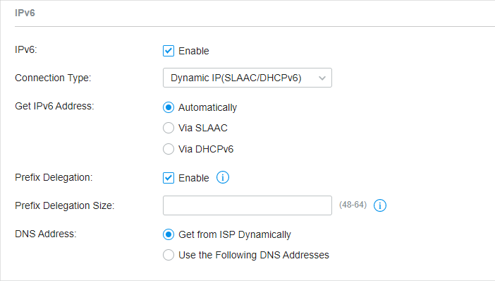
|
Get IPv6 Address |
Automatically : With this option selected, the gateway will automatically select SLAAC or DHCPv6 to get IPv6 addresses. Via SLAAC : With SLAAC (Stateless Address Auto-Configuration) selected, your ISP assigns the IPv6 address prefix to the gateway and the gateway automatically generates its own IPv6 address. Also, your ISP assigns other parameters including the DNS server address to the gateway. Via DHCPv6 : With DHCPv6 selected, your ISP assigns an IPv6 address and other parameters including the DNS server address to the gateway using DHCPv6. |
||||
|
Prefix Delegation |
|
Prefix Delegation Size |
|
DNS Address |
Get from ISP Dynamically : The DNS address will be automatically assigned by the ISP. Use the Following DNS Addresses : Enter the DNS address provided by the ISP. |
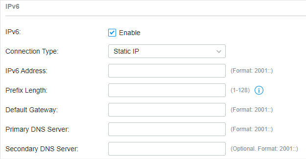
�? Static IP
Choose Connection Type as Static IP and configure the following parameters. Then click Apply .
|
IPv6 Address |
|
Prefix Length |
|
Default Gateway |
|
Primary DNS Server |
|
Secondary DNS Server |
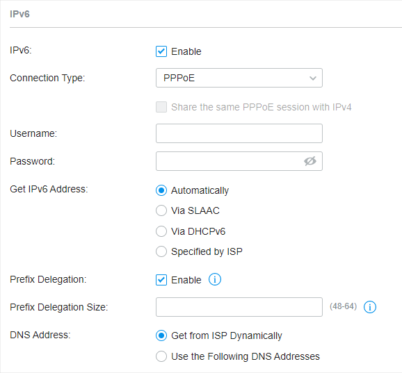
�? PPPoE Choose Connection Type as PPPoE and configure the following parameters. Then click Apply .
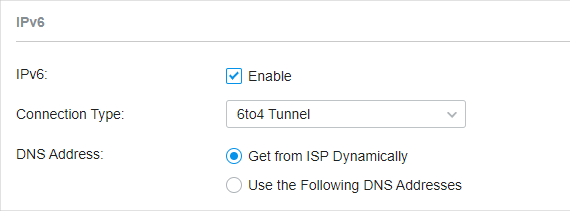
�? 6to4 Tunnel Choose Connection Type as 6to4 Tunnel and configure the following parameters. Then click Apply .
�? Pass-Through (Bridge) Choose Connection Type as Pass-Through (Bridge) and no configuration is required for this type of connection Then click Apply .
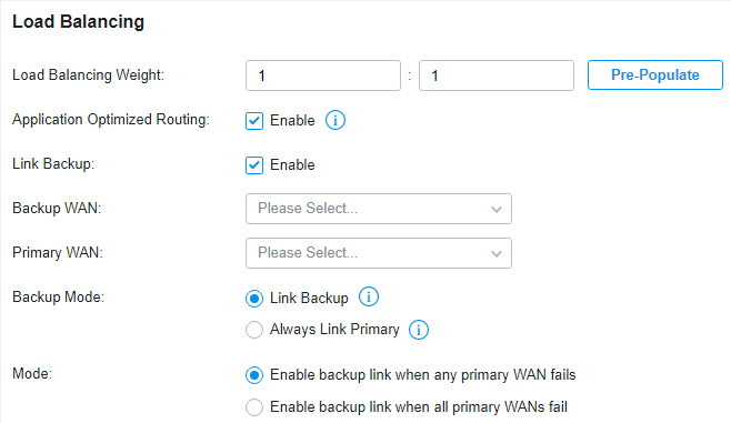
Go to Settings > Wired Networks > Internet to load the following page. In Load Balancing , configure the following parameters and click Apply .
| ||||||||||||||||||||||||||||||||||||||||||||||||||||||||||||||||||||||||||||||||||||||||||||||||||||||||||||||||||||||||||||||||||||||||||||||||||||||||||||||||||||||||||||||||||||||||||||||||||||||||||||||||||||||||||||||||||||||||||||||||||||||||||||||||||||||||||||||||||||||||||||||||||||||||||||||||||||||||||||||||||||||||||||||||||||||||||||||||||||||||||||||||||||||||||||||||||||||||||||||||||||||||||||||||||||||||||||||||||||||||||||||||||||||||||||||||||||||||||||||||||||||||||||||||||||||||||||||||||||||||||||||||||||||||||||||||||||||||||||||||||||||||||||||||||||||||||||||||||||||||||||||||||||||||||||||||||||||||||||||||||||||||||||||||||||||||||||||||||||||||||||||||||||||||||||||||||||||||||||||||||||||||||||||||||||||||||||||||||||||||||||||||||||||||||||||||||||||||||||||||||||||||||||||||||||||||||||||||||||||||||||||||||||||||||||||||||||||||||||||||||||||||||||||||||||||||||||||||||||||||||||||||||||||||||||||||||||||||||||||||||||||||||||||||||||||||||||||
.png)

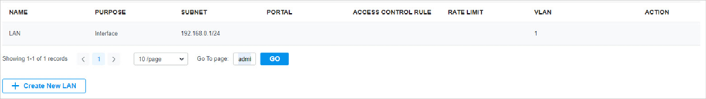
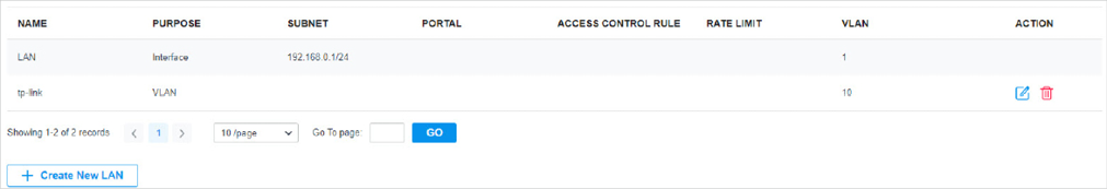
 in the ACTION column to edit the LAN. You can click
 in the ACTION column to delete the LAN.
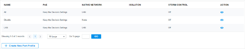
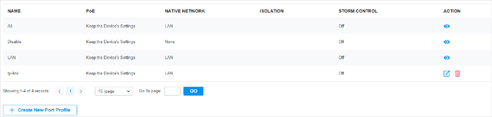
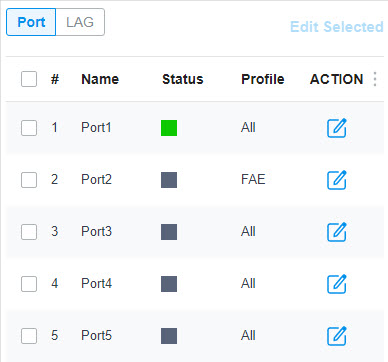
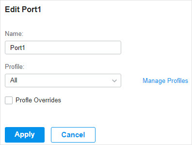
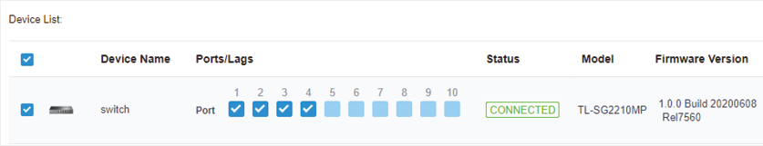
 in the Action column to assign the port profile to a single port, or select the desired ports and click


 to load the following page.
 to load the following page.
 to load the following page.
 to load the following page.
 to load the following page.
 to delete them.
 to load the following page.
 to load the following page.
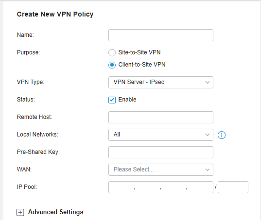
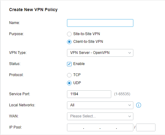
 in the Action column to export the OpenVPN file that ends in .ovpn which is to be used by the remote client. The exported OpenVPN file contains the certificate and configuration information.
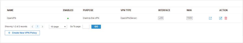


.png)
 to delete them.
 to delete them.


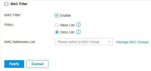
 to allow it to override the curent MAC Access Control List.

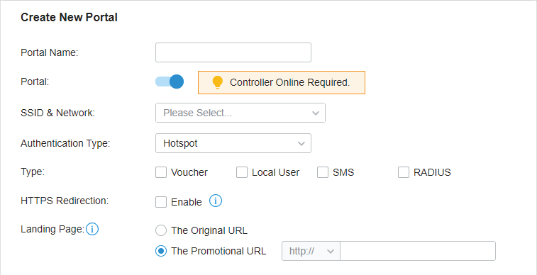
 to create new Portal entry.
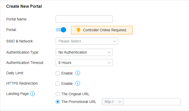
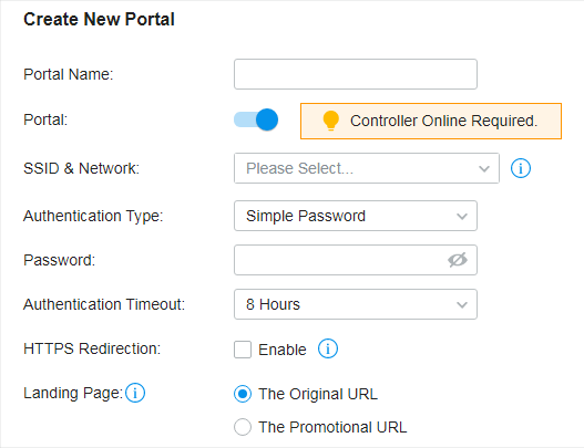
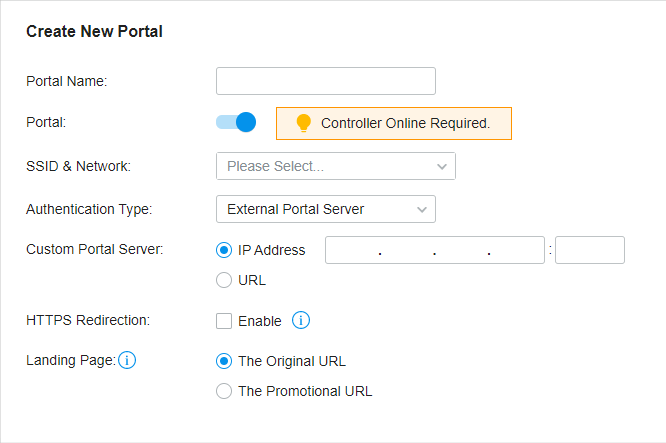
 to enable Portal, select the SSIDs and LAN networks for the portal to take effect on and configure basic parameters including authentication type, authentication timeout and so on.
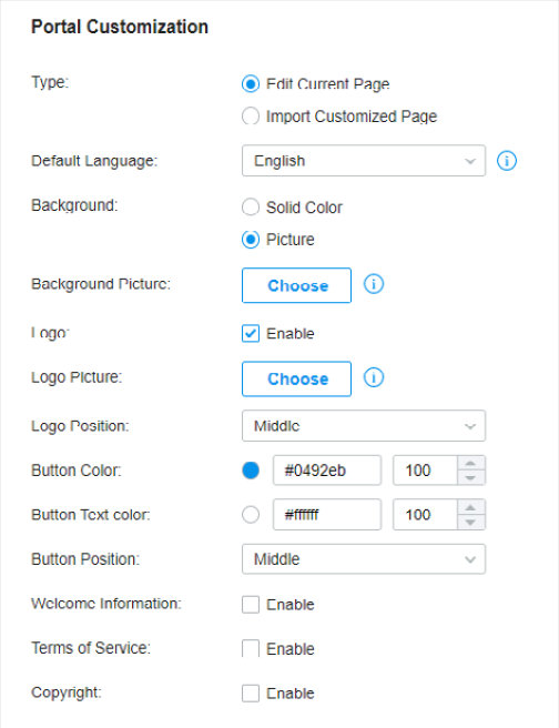
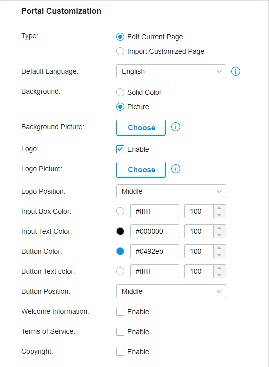
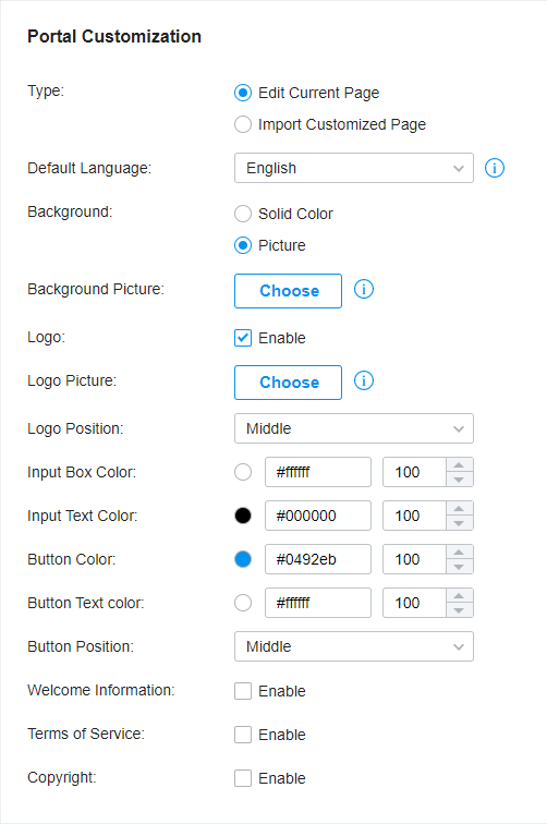
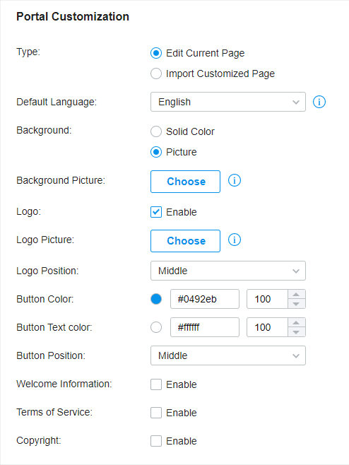
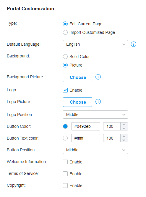
 to import your unique Portal page for branding it as per your business.
 and select a picture from your PC as the background.
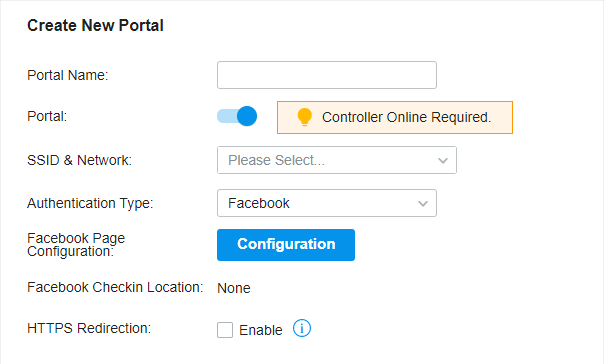
 to create new portal entry. Then click
 to enable Portal and load the following page.
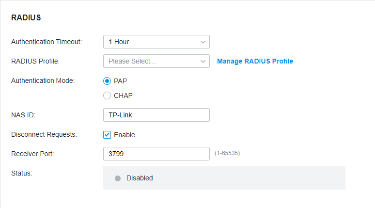
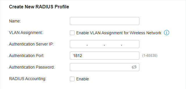
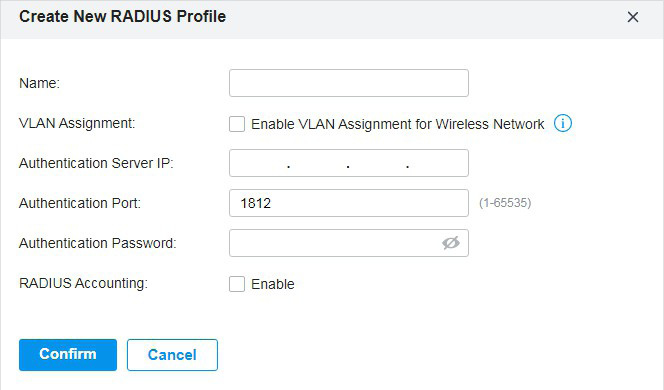
 to create one. The RADIUS profile records the information of the RADIUS server which provides a method for storing the authentication information centrally.
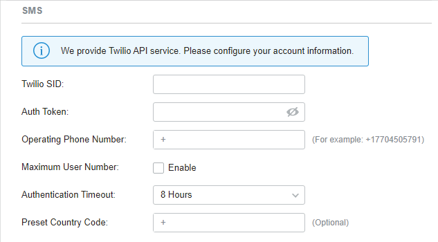
 to enable Portal and load the following page.
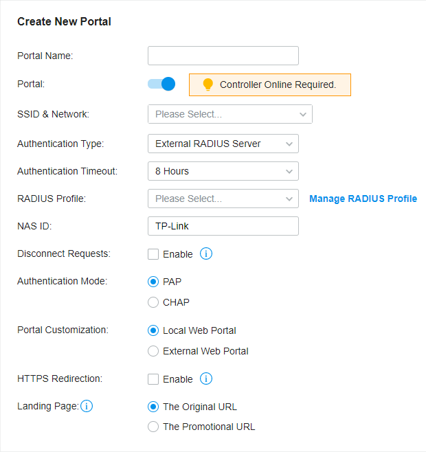
 to create one. The RADIUS profile records information of the RADIUS server including the IP address, port and so on.
 to import your unique Portal page for branding it as per your business.
 and select a picture from your PC as the background.
 to create new portal entry. Then click
 and select a picture from your PC as the background.
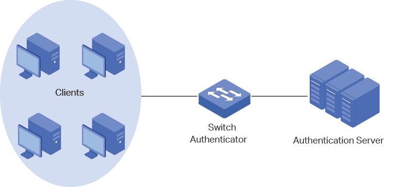
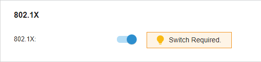
 to enable 802.1X.
 from the drop-down list or
 to create one. The RADIUS profile records the information of the RADIUS server which acts as the authentication server during 802.1X authentication.
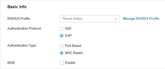
 . To enable MAB, click the ports marked with
 . You can enable MAB only on 802.1X-enabled ports. MAB-enabled ports will be marked with
 .
.

 to enable MAC-Based Authentication.

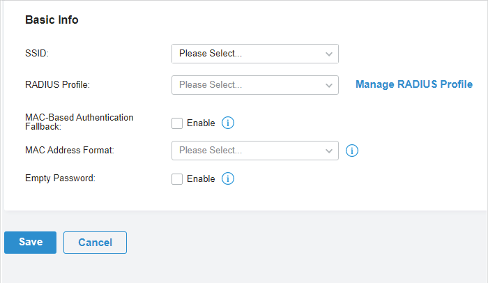
 to create one. The RADIUS profile records the information of the RADIUS server which acts as the authentication server during MAC-Based Authentication.
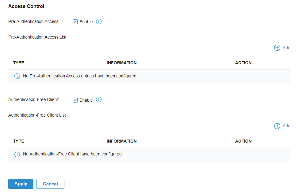
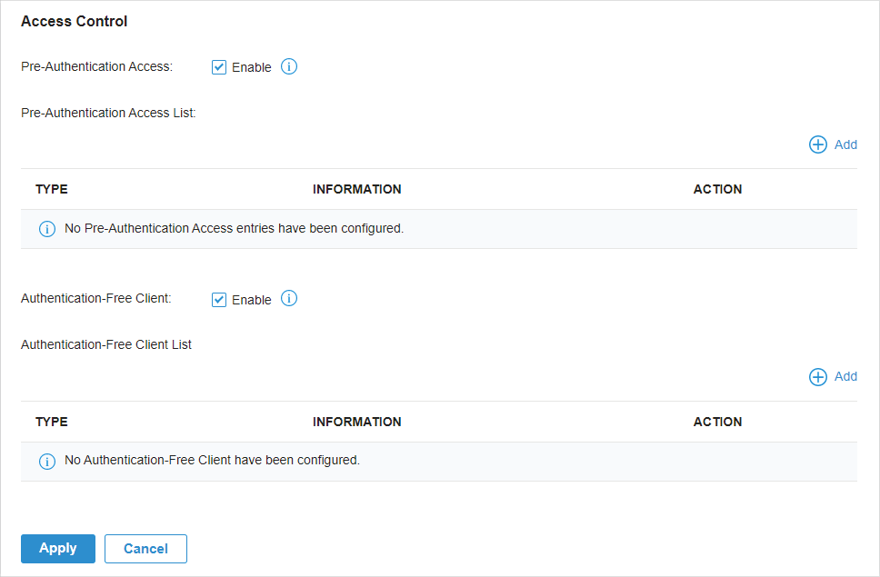
 to load the following page.