Catalogue
VIGI Cloud VMS_User Guide
About This Guide
About This Guide
This User Guide provides information for managing devices via TP-Link VIGI VMS platform.
Conventions
When using this guide, notice that:
■ Features available of VIGI devices may vary due to your region, device model, firmware version, and app version. All images, steps, and descriptions in this guide are only examples and may not reflect your actual experience.
■ The information in this document is subject to change without notice. Every effort has been made in the preparation of this document to ensure accuracy of the contents, but all statements, information, and recommendations in this document do not constitute the warranty of any kind, express or implied. Users must take full responsibility for their application of any products.
■ This guide uses the specific formats to highlight special messages. The following table lists the conventions that are used throughout this guide.
|
Underlined |
Indicates hyperlinks. You can click to redirect to a website or a specific section. |
|
Bold |
Indicates contents to be emphasized and texts on the web page, including the menus, tabs, buttons and so on. |
|
> |
The menu structures to show the path to load the corresponding page. |
|
Caution |
Reminds you to be cautious, and Ignoring this type of note might result in device damage or data loss. |
|
Note |
Indicates information that helps you make better use of your device. |
More Information
■ The latest firmware can be found at Download Center at https://www.tp-link.com/support.
■ Product specifications can be found on the product page at https://www.tp-link.com.
■ For technical support, the latest version of the Quick Installation Guide, User Guide and other information, please visit https://www.tp-link.com/support.
■ To ask questions, find answers, and communicate with TP-Link users or engineers, please visit https://community.tp-link.com to join TP-Link Community.
Chapter 1 Introducing VIGI VMS
This chapter covers the basic functionalities and the latest features of VIGI VMS.
1. 1 Introduction
VIGI VMS is a local-deployed software system designed for centralized management of medium-scale surveillance projects like supermarkets, hotels and schools. It includes features such as real-time video monitoring, user permission management, alarm handling, evidence collection, and virtual map integration, aiming to enhance your video management efficiency.
The software provides multiple functionalities, including:
Device Access: Detect and add IPCs and NVRs.
Device Management: Remotely configure the IPCs and NVRs, reboot and upgrade the devices, and edit image and video parameters, etc.
Real-time Monitoring: Check the surveillance video in real-time, monitor the site, and perform functions of intercom, alarm, PTZ control, etc.
Alarm Events: Receive and deal with the alarm events, view the event’s details, and solve the exceptions in time.
Video Playback: Backtrack and search for videos.
E-Map: Upload the map or floor plan to VMS, and label the monitoring points straightforwardly.
User & Site: Support multi-user access and multi-site for flexible control of the permission of varied users.
Cloud Access: Supports VMS remote login and management.
Maintenance & Management: Manage the logs, record the user’s operation, and configure the history and alarm logs.
This user manual describes the functions, configurations and operation steps of VIGI VMS. To ensure proper usage and stability of the software, please read the manual carefully before installation and operation.
1. 2 What’s New
Compared to the previous versions, the 2.1 version has the key following updates:
New Features:
• Expanded Device Management: Added support for managing solar panels, switches, and accessories. Devices can now be priced automatically with total cost calculations.
• Custom Alerts: Configure alert groups based on specific conditions and apply them to all users within your organization. Alerts can now be easily muted, edited, and automatically applied.
• Project Management: New functionality for managing multiple floor plans in Design Tool, including the ability to create private projects, import/export projects, and create project copies.
• Simultaneous Video Playback Count: Display the number of people viewing videos simultaneously.
• Solar Device Access: Viewer/Live Only role users can now view solar device power statistics.
Enhancements:
• UI and Branding Updates: Updated theme color and new VIGI brand logo for a refreshed interface.
• Playback and Device Performance: Improved fast-forward playback, continuous playback across days, and faster device configuration page interactions.
• Event and Alert Optimization: Refined event detection types and alert filtering. Added new event types such as Device Online and enhanced alert management features.
• AI and Security Optimizations: Enhanced AI service performance and added RSA encryption to improve data security and ensure safe transmission of sensitive information.
• Device Model Support: New device models like Insight S425, EasyCam C420, and others are now supported in Design Tool.
• AI Video Search: Enhanced search capabilities with support for Person of Interest and facial recognition.
• FTP Backup for NVRs: Added FTP Backup functionality for NVRs, allowing users to back up video data to an external FTP server for added security.
Chapter 2 Add Monitoring Devices
This chapter provides step-by-step instructions for adding and managing monitoring devices within the VIGI VMS.
VIGI VMS offers several options for adding devices, such as Auto Add, Manual Add, and Remote Add. Additionally, it allows for batch additions, which makes it easy and convenient to add a large number of devices at once.
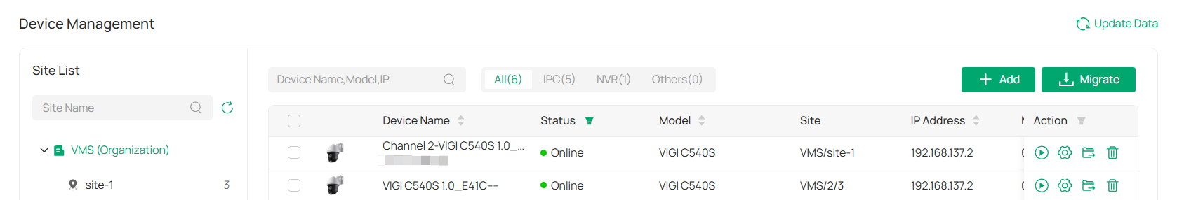
1. Hover the cursor over the menu bar on the left side of the main screen to reveal the names of each function. Click Devices to enter the device management page.
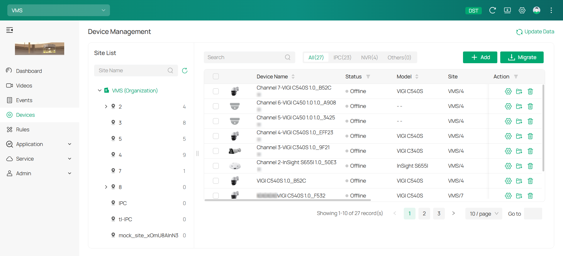
2. On the device management page, you’ll find the Site List in the sidebar. When you first use VMS, the system automatically creates a default site for you. You have the option to modify, add, or remove sites in the Admin > Site section.
3. The Device List is displayed on the main screen of the device management page, showing all devices added to the current site. Within the Device List, you can add new devices, transfer devices to different sites, or remove devices from the current site.
4. Click +Add![]() on the top right corner of the Device List, and the Add Device window will appear.
on the top right corner of the Device List, and the Add Device window will appear.
2. 1 Auto Add Device
2. 1. 1 When the device and the VMS server are in the same network segment
1. On the Add Device page, click Auto Add. A list of detected devices will appear. To add a device, click + on its right. If you wish to add several devices simultaneously, check the boxes next to them and click Add All.
2. Choose a site from the drop-down list in Add to Site and click Confirm and Next.
3. (Optional) Create a new site:
1) Click on Add Site.
2) Set up the following parameters:
|
Feature |
Explanation |
|---|---|
|
Site Name |
Enter a descriptive name for the site. |
|
Main Site |
Enter the primary location or central hub where the camera system is managed or monitored. |
|
Country/Region |
Select the location of the site. |
|
Time Zone |
Select the time zone of the site. |
|
Daylight Saving Time |
Set DST (daylight saving time) parameters. You can select Auto at the dropdown list. Note that to update the time automatically with the DST, internet connection is required. Or you can select Manual and specify the date/time and the bias time (the difference in minutes between standard time and daylight-saving time for a specific time zone). |
|
Sync to Devices |
Enable Sync to Devices to synchronize the time across all devices with the PC running VMS. |
4. A prompt will appear asking you to verify your device password. Enter your username and password, and click Confirm.
5. Return to the Device List page to check if the device is listed. If it is, the device has been added successfully. To add an NVR device, follow the same instructions.
2. 1. 2 When the device and the VMS server are different network segments
1. Ensure the device’s IP address is in the same network segment as the VMS server. If not, click  to adjust the network settings and click + to add it automatically.
2. Configure the device to match the VMS server’s network segment and click Confirm.
Note: If they are already in the same segment, follow the steps in When the device and the VMS server are in the same network segment to proceed.
2. 2 Manually Add Device
Go to the Add Device page and click on Manually Add. You can choose to add an IPC with its serial number or Device ID.
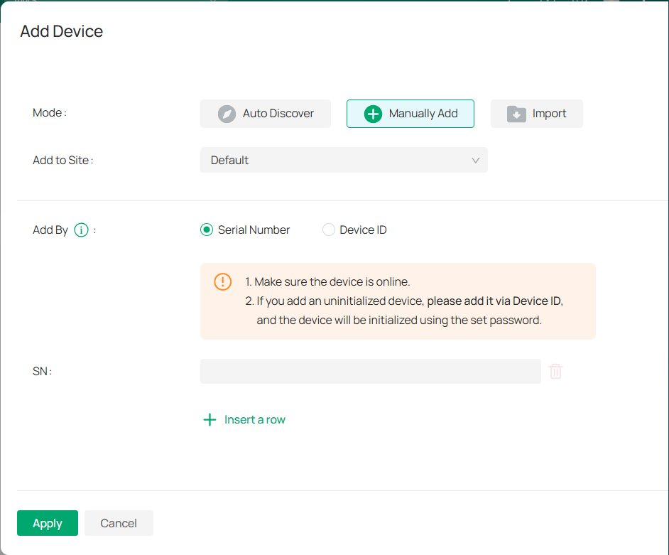
■ To add a device via serial number:
1) Select the site from the Add to Site drop-down.
2) Select Serial Number in the Add By field.
3) Enter the device’s serial number. It can be found at the bottom of the device.
4) (Optional) To add more than one device at once. click Insert a row and enter another serial number.
5) Click Apply.
■ To add a device via Device ID:
1) Select the site from the Add to Site drop-down.
2) Select Device ID in the Add By field.
3) Enter the device’s Device ID. It can be found at the bottom of the device.
4) (Optional) To add more than one device at once. click Insert a row and enter another Device ID.
5) Click Apply.
2. 3 Import Devices
Go to the Add Device page and click on Import.
1) Select the site from the Add to Site drop-down.
2) Click the template to download it.
3) Fill in your devices’ information.
4) Click Browse to upload the file.
5) Click Apply.
2. 4 Move Device to Another Site
To relocate devices to different sites, you can adjust the site settings after adding the device in the Device List.
1. Click ![]()
![]() , and the Move Device window will appear.
, and the Move Device window will appear.
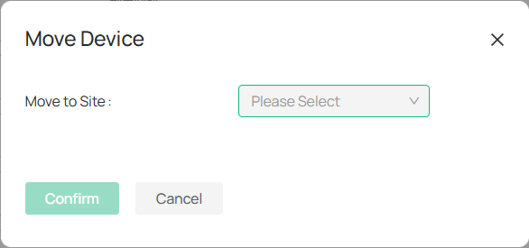
2. From the drop-down menu, choose the new site where you want the device to be transferred.
3. Click Confirm to finalize the move.
Chapter 3 Home Page Overview
This chapter provides an overview of the Home Page and Dashboard, your central hub for accessing core system functions, managing organizations, downloading clients, adjusting settings, and handling profile preferences. It also introduces quick operations such as adding or searching for sites, viewing events and device trends, and managing locations directly on the map.
3. 1 Dashboard
The Dashboard is your central hub for managing settings, accessing key features, and viewing your system status. Below is an overview of the features and actions available on the dashboard:
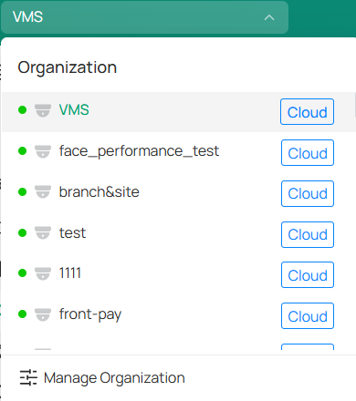
■ Icons
Manage Organizations: Click the current organization name to switch between organizations. In the drop-down list, select your desired organization. To search for an organization by name, filter organizations by type (local or cloud).

 \
\
To add a new organization, click Manage Organizations at the bottom of the list.
1. In the organization list page, click 
 .
.
2. In the pop-up window, fill out organization name, specify the country or region, and select the time zone.
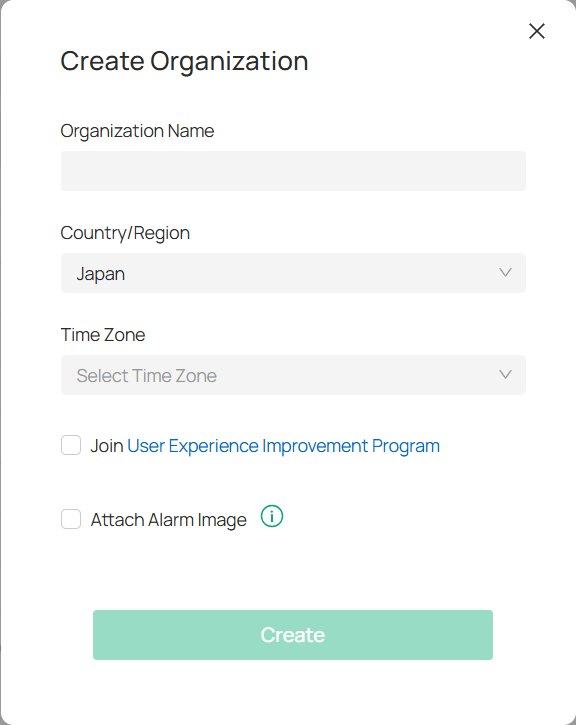
3. Click Create.
Collapse: Click ![]()
![]() to expand or hide the side navigation tabs for a more streamlined view.
to expand or hide the side navigation tabs for a more streamlined view.
■ Download
PC Client: (For Windows only) Download the PC client for an enhanced video viewing experience with additional features designed for optimal performance.
Web Plugin: (For Windows only) Install the web plugin to unlock extended features for Live View and Playback.
■ Preference
Language: Choose your preferred language for the interface.
Theme: Switch between Light and Dark modes to suit your visual preference.
■ Profile
Account Settings: View and manage your email address, data storage location, and security settings. You can also enable Two-Factor Authentication and change your password for added protection.
Services: Access cloud backup services. For more details, refer to Cloud Backup Service.
Audit Log: Review your account’s activity log. For more information, refer to Log.
■ More
Tutorial: Explore new features and step-by-step operation instructions to help you get the most out of your system.
Feedback: Provide feedback or suggestions for improvements.
Contact Support: Reach out to customer support for assistance.
About: Check out the version of the system.
3. 2 Quick Operations
3. 2. 1 Add a Site
1. Right-click on the desired location on the map and select Add New Site.
2. In the pop-up window, fill in all the required fields:
|
Site Name |
Enter a name for the new site. |
|---|---|
|
Main Branch |
Specify the organization the site belongs to. |
|
Country/Region |
Choose the country or region where the site is located. |
|
Time Zone |
Select the time zone for your site. |
|
Daylight Saving Time |
Choose Auto to update time automatically with DST (requires internet connection), or Manual to set the date/time and specify the time bias. |
|
Sync to Devices |
Enable or disable synchronization with the main site. |
|
Address |
Enter the site’s address, city, etc. |
|
Longitude & Latitude |
Optionally provide the site’s exact geographical coordinates. |
3. Click Add.
3. 2. 2 View Details of a Site
Click a site on the map to view information such as the number of NVRs, cameras, solar systems, latest alarms, and event recordings.
Click ![]()
![]() to watch the live view or click the Custom Event section for recorded events.
to watch the live view or click the Custom Event section for recorded events.
3. 2. 3 Search a Site/Address
To search a site, use the search bar in the middle upper part of the screen.


To search an address, select Address in the search bar drop-down and enter an address.


To search an unplaced address, go to the Unplaced Site List  on the left to search for a site not yet placed on the map.
3. 2. 4 View Events/Trends/Devices
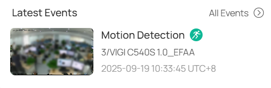
Latest Events: At the right of the homepage, view a quick overview of the most recent events, devices, and sites. Click All Events to go to the detailed Events page for more info.

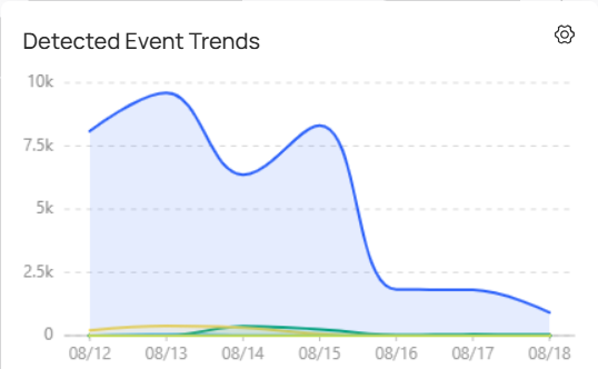
Events Trends: View the daily event alarm trend in the graph at the bottom-right of the homepage. Click the Settings icon to adjust the time range and displayed sites/devices.

Devices: Click Cameras or NVRs at the top to be redirected to the Device Management page for detailed configurations.

3. 2. 5 Manage the Map/Location
Drag a Site to the Map: In the Unplaced Site List, drag the site to the desired location on the map. Right-click on the site to edit its location or remove it.
Zoom In: Double-click on the map or click 
 at the bottom left corner.
Zoom Out: Click 
 at the bottom left corner.
Find My Location: Click 
 to center the map on your current location. (Note: Ensure location access is enabled).
Chapter 4 Live View
The Live View chapter introduces real-time monitoring, allowing you to watch camera feeds, manage layouts, and interact with devices instantly. It helps you stay aware of ongoing activities and respond quickly to events as they happen.
4. 1 Create a View
In the Live View module of VIGI VMS, you can monitor live video feeds from added cameras and perform basic operations, such as capturing pictures, recording video, and controlling PTZ (Pan-Tilt-Zoom) functions. You can access Live View from the Videos tab on the left.
A View is a window division where resource channels (e.g., cameras, access points) are linked to each window. Views allow you to save window divisions and the correspondence between cameras and windows for quick access later.
1. To create a new view, go to Videos.
1) Click the + icon next to the View section.
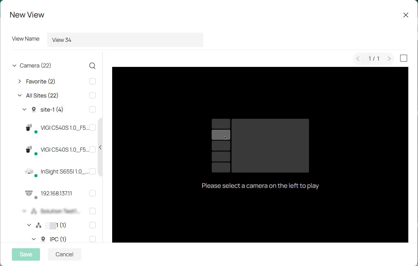
2) In the New View window, enter a name for your view and select the checkboxes next to the devices you want to include in the view.
2. Define window division. Click 
 in the upper right corner and select the number of camera live view feeds you want to display on your screen simultaneously.
• Note: Auto Layout automatically arranges the optimal number of live view feeds for your selected cameras to ensure the best aesthetic effect.
3. After selecting the devices and window layout, click Save to store your new view.
4. To modify your view, click ![]()
![]() next to the view’s name. You can choose to Edit View (change devices or window layout), Rename, or Delete the view.
next to the view’s name. You can choose to Edit View (change devices or window layout), Rename, or Delete the view.
4. 2 Start Live View
You can start watching live camera views in a few ways: from your favorite cameras, through a site, and using a web plugin.
4. 2. 1 Start Live View of Favorited Cameras
1. In the Camera List, click the more icon next to a camera’s name and select Favorite to add it to your Favorites list.
2. To start the live view, click ![]()
![]() next to Favorites. This will show the live view of all the cameras in your Favorites list.
next to Favorites. This will show the live view of all the cameras in your Favorites list.
4. 2. 2 Start Live View of Cameras in a Site
Click ![]()
![]() next to a site or sub-site to view the live feeds from all cameras in that site or sub-site in batches.
next to a site or sub-site to view the live feeds from all cameras in that site or sub-site in batches.
4. 2. 3 Live View via the Plugin
1. Click ![]()
![]() at the upper right of the screen to download the web plugin.
at the upper right of the screen to download the web plugin.
2. Click ![]()
![]() at the upper right of the live view feed and select Web Plugin to enable the plugin for enhanced live viewing.
at the upper right of the live view feed and select Web Plugin to enable the plugin for enhanced live viewing.

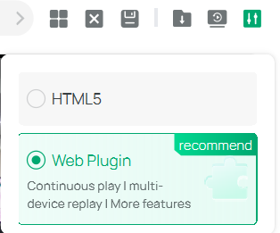
Note: With recent updates to the Chrome engine, plugin switching may not work in some setups (for example, Windows 11 with Microsoft Edge 139 or Chrome 139 and later). If you run into issues enabling the plugin, try using a different browser or contact our support team for assistance.
4. 2. 4 Icon Explanation
On the Live View page, you might see these icons below. Check this table to understand how they function:
|
Icon |
Function Name |
Description and Operation |
|
|
Play/Pause |
Start or stop the live view feature. |
|
|
Resolution |
Change the video display resolution. |
|
|
Screenshot |
Take manual snapshots for the live view window. |
|
|
Record |
Click once to begin recording, and click again to end it; the recordings will be automatically saved to your designated path. |
|
|
Instant Playback |
Replay the last 30 seconds of video. |
|
|
Digital Zoom |
Zoom in to get a closer look at the image for finer details; zoom out for a wider panoramic image. |
|
|
Volume |
Toggle the live view cameras between mute and unmute. Adjust the volume by dragging the volume slider. |
|
|
Talk |
Communicate with someone near the camera. |
|
|
Alarm |
Send siren alerts and instant notifications. |
|
|
Pan & Tilt |
(Available for select models only) Used for adjusting the image’s brightness; a larger iris allows more light in, resulting in a brighter picture. |
|
|
Smart Frame |
Smart frame is an AI-powered function that can precisely mark and capture detected movement, people, or vehicle objects on the screen. |
|
|
Ratio |
Select the aspect ratio. |
|
|
Panoramic |
(Available for fisheye models only) |
|
|
Settings |
Click to configure display and stream parameters. For detailed operations, refer to Camera Display Settings and Camera Stream Settings. |
|
|
Full Screen |
View the live feed in full screen; press the Esc key to exit full screen mode. |
|
|
Number of Screen |
Select how many camera feeds appear on the screen, such as 1, 4, 9, or 16. You may watch up to 64 views simultaneously. |
|
|
Clear Window |
Reset the display by removing all active video feeds and returning the layout to default. |
|
|
Save View |
Click to save a snapshot of the live camera feed. |
|
|
Configuration |
Select your viewing mode. For HTML5, you can watch the live feed from one camera at a time. For Web Plugin, you can view up to four camera feeds simultaneously. |


Chapter 5 Playback
The Playback chapter focuses on reviewing recorded video, giving you tools to search, filter, and analyze past events. It enables efficient incident investigation and ensures important footage is easily accessible when needed.
Playback allows you to view a segment of the video that stands out or may not be clear at first glance. You can quickly access video files on the Live View page for an immediate review if necessary. You can watch playback from up to four cameras at once.
Before you start, make sure to record your video files and save them on storage devices like SD/SDHC cards, HDDs, DVRs, NVRs, network cameras, or storage servers.
1. Go to Videos > Playback.
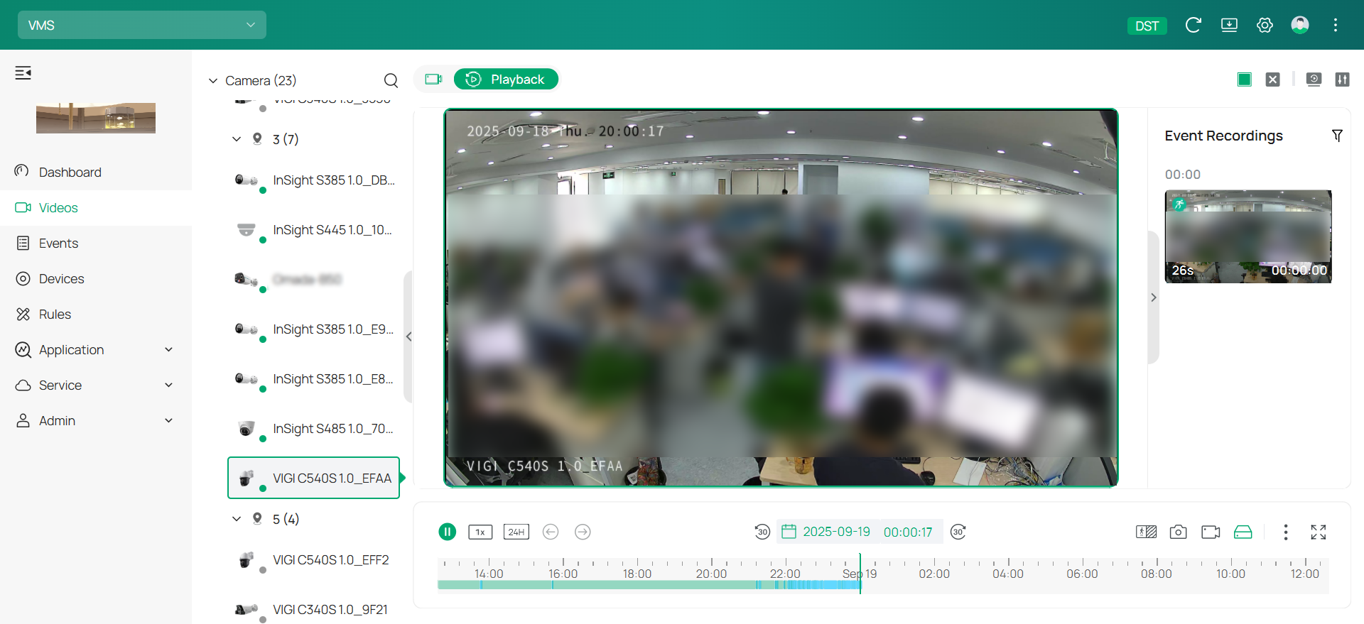
2. Choose the camera from the device list on the left and specify a date below the display window. Double-click the event recording you want to watch from the right list.
3. For detailed configuration, navigate to the toolbar at the bottom or use the quick config options available in the upper right.
|
Icon |
Description and Operation |
|---|---|
|
|
Hit to pause or resume the playback. |
|
|
Speed Playback: Increase the speed for fast-forward or decrease for slow-motion review. |
|
|
Time Span: Click to change the period of time between 10 minutes to 24 hours. |
|
|
Show the previous event. |
|
|
Show the next event. |
|
|
Click to open the time picker and select a time and date to go to a specific point in time in the video. |
|
|
Skip back 30 seconds. |
|
|
Skip forward 30 seconds. |
|
|
Resolution: Click to change the resolution type. HD stands for high definition. SD stands for standard definition. HD offers a higher pixel count and therefore a sharper, more detailed image than SD. SD with HD Event: This method records events in high definition and uses standard definition for other video times. It saves storage space while keeping important details for key events. |
|
|
Screenshot: Take manual snapshots for the live view window. |
|
|
Record: Click once to begin recording, and click again to end it; the recordings will be automatically saved to your designated path. |
|
|
Switch between local and cloud storage. |
|
|
Digital Zoom: Zoom in to get a closer look at the image for finer details; zoom out for a wider panoramic image. Sound: Click to adjust the volume of the speaker. |
|
|
Full Screen: Click to change the live view image to the entire screen. |
|
|
Number of Screen: Select how many camera feeds appear on the screen, such as 1, 4, 9, or 16. You may watch up to 64 views simultaneously. |
|
|
Clear Window: Reset the display by removing all active video feeds and returning the layout to default. |
|
|
Configuration: Select your viewing mode. For HTML5, you can watch the live feed from one camera at a time. For Web Plugin, you can view up to four camera feeds simultaneously. |


Chapter 6 Events and Alerts
The Events and Alerts chapter explains how the system captures, displays, and manages notifications triggered by devices or activities. It provides tools to review event details, configure alert settings, and ensure you stay informed of critical incidents in real time.
The Events feature in VIGI VMS is a crucial tool for monitoring and responding to irregular activities detected by your cameras. It helps security staff stay alerted to any potential security threats, allowing for rapid intervention. The system can trigger various linked actions, such as audio alerts or email notifications, to ensure immediate attention is given to any suspicious events.
6. 1 Device Event
A Device Event records any alarm or alert triggered by the devices connected to the VMS system. These events may include motion detection, person detection, and other anomalies that require attention.
■ Search for Smart Events
VMS allows you to search for specific smart events based on your preferences. Follow these steps to efficiently locate the events you need:
1. Click Events in the menu bar.
2. Once in the Events section, you’ll see the list of recorded smart events. These events are organized by device type, event type, and time, allowing for easy filtering.
3. Click 
 and
and 
 to switch between two event viewing modes: Thumbnail Mode and List Mode. Thumbnail Mode shows you a small preview image of the event. List Mode provides a more detailed, text-based view of the events.
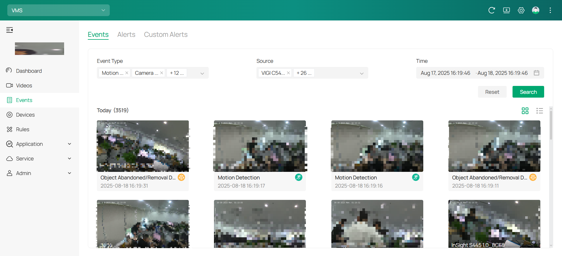 4. To narrow down your search, you can use filters. Choose the specific Event Type (e.g., Motion Detection, Person Detection) and Source (the camera or device responsible for the alert).
5. Set the desired Time Range to focus on events that occurred within a specific timeframe. After adjusting the filters, click Search to view the results.
■ Event Playback
The Event Playback feature allows you to view past events captured by your devices. This functionality helps you investigate suspicious activities or review event details to make informed decisions.
1. In the event list, find the event you want to review. Click on the event to view its playback and real-time preview.

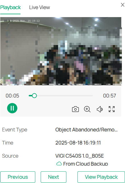
2. A pop-up window will appear displaying the event’s live view or playback. The time bar at the bottom of the playback window allows you to navigate through the event’s timeline. You can pause or play the video using the controls at the bottom.
3. Click on ![]()
![]() to capture still images from the video.
to capture still images from the video.
4. Click 
 to expand the video to full-screen mode for a better view.
5. To get a closer look at specific areas in the video, click ![]()
![]() . This will allow you to zoom in on the video for more details. You can also drag your mouse over the video to explore different areas, giving you a more detailed view of the footage.
. This will allow you to zoom in on the video for more details. You can also drag your mouse over the video to explore different areas, giving you a more detailed view of the footage.
■ Enable/Disable the Message
To ensure that you are notified of important events and updates, you can enable or disable message notifications for specific devices. This includes receiving alerts for alarm events or offline status of the devices. Follow these steps to manage the message notifications for a device:
1. Click on the Devices tab in the menu on the left side.
2. In the Device List, find the device for which you want to manage message notifications. Click  to open the device management settings.
3. Click Events > Message.
4. Enable Alarm Message or Offline Message as needed.
|
Alarm Message |
Toggle this option on to receive notifications whenever an alarm event is triggered by the device. |
|---|---|
|
Offline Message |
Enable this to be notified when the device goes offline. |
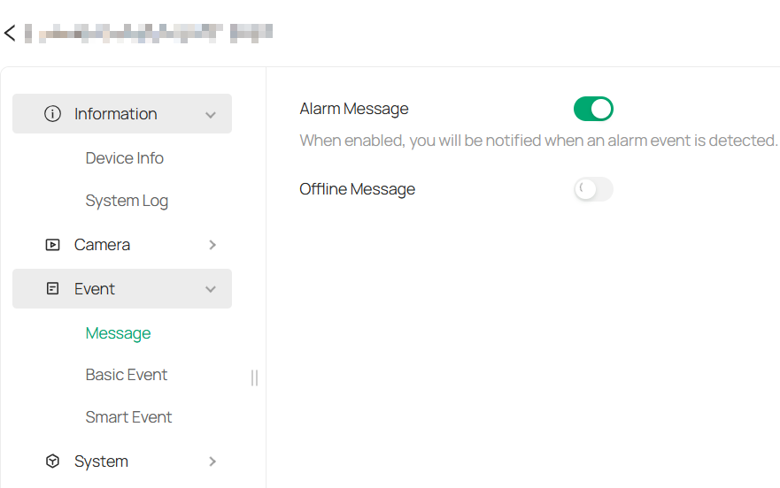
Note: The Offline Message feature is unavailable for IP cameras that are connected to a Network Video Recorder.
6. 2 Alerts
The Alerts section lets you easily manage, filter, and take action on the alerts generated by your system. You can quickly search for alerts, resolve or delete them, and even export the data for further review. The Custom Alerts feature allows you to set up personalized notifications, helping you stay on top of specific events and devices.
6. 2. 1 View and Edit Alerts
1. Go to Events > Alerts. You’ll see a list of recorded smart events. Alerts are organized by device, alert type, severity, status (resolved or unresolved), and time.
2. Use the search bar to find alerts by device name or event details.
3. To resolve an alert, click ![]()
![]() to mark an alert as resolved.
to mark an alert as resolved.
4. To delete an alert, click ![]()
![]() to remove the alert from the list.
to remove the alert from the list.
5. To export alerts, click 
 to download the alert log to your computer. Choose between CSV or XLS formats and click Export.
6. 2. 2 Set Up Custom Alerts
The Custom Event feature allows you to set up personalized alerts triggered by specific conditions defined in the event rules. By configuring custom events, you can receive notifications based on your chosen parameters, enhancing the monitoring capabilities of your system.
1. Go to Events > Custom Alerts.
2. Click ![]()
![]() to the right of Custom Alerts to enter the Create Custom Alert page.
to the right of Custom Alerts to enter the Create Custom Alert page.
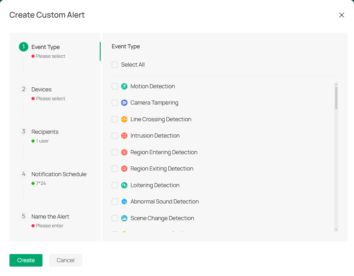
3. In the Event Type section (Step 1), select the type of event you want to create.
4. In Step 2, select the devices for which you want to create the custom event.
5. In Step 3, you will choose the recipients of the alert. This can be a specific user or a group of users who will be notified when the event occurs
6. In Step 4, configure the Notification Schedule to determine when you want to receive event notifications. The default schedule is 24/7.
7. In Step 5, enter a Name for your custom alert.
8. After filling in all the necessary details, click the Create button at the bottom to save and activate your custom event alert.
After creating your custom alerts, you may:
• Edit Alert Group: Click ![]()
![]() next to a group and select Edit to modify the alert conditions.
next to a group and select Edit to modify the alert conditions.
• Mute Notifications: Click ![]()
 next to a group and select Mute Alert. Choose how long to mute notifications for that group.
• Mute All Groups: Click ![]()
![]() next to Custom Alerts to mute all groups at once.
next to Custom Alerts to mute all groups at once.
• Filter them by: alert type, device, and time range. This allows you to quickly find the alerts that matter most to you.
Chapter 7 Rules
The Rules chapter introduces how to automate and simplify device management within your VMS. By creating Device Rules, you can batch-configure devices, standardize event handling, and execute actions directly from the server side. In addition, the module supports Device Maintenance rules, enabling you to schedule routine tasks—such as reboots or updates—to ensure consistent system performance without manual effort.
In the Rules module, Device Rules enable you to set general rules for managing devices within your VMS. These rules allow for streamlined batch configuration of devices and tailored event processing. The rules are executed on the server side to effectively handle events triggered by the devices.
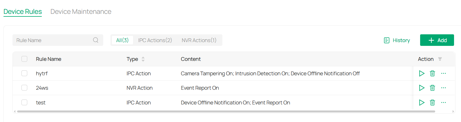
7. 1 Device Rules
■ View Rules
1. Click Rules in the menu bar.
2. The main screen will display the list of active rules.
3. You can filter the list by type or use the fuzzy search bar for easier navigation.
■ Add/Edit Rules
To add rules, follow these steps:
1. In the Rules section, click ![]()
![]() in the top right corner.
in the top right corner.
2. A pop-up window will appear where you can fill in the necessary details for the new rule.
3. From the Action drop-down menu, choose the specific actions you want to configure for the device.
4. If you need to add additional actions, click + Add below the drop-down. The actions will be executed in the order they are added.
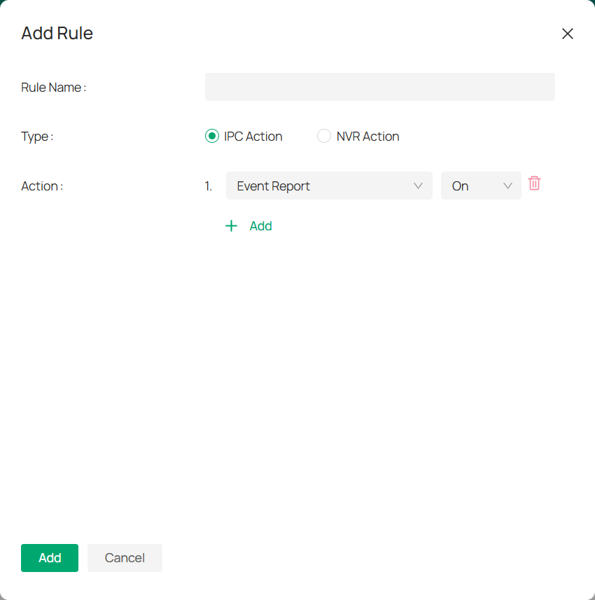
5. Click Add.
To edit rules, follow these steps:
1. Click 
 in the Action column of the rule list and click Edit.
2. In the Edit Rule window that appears, modify the rule details as needed. From the Action drop-down menu, choose the specific settings you want for the device.
3. If you need to add more actions, click + Add below the drop-down menu. The actions will be executed in the order they are added.
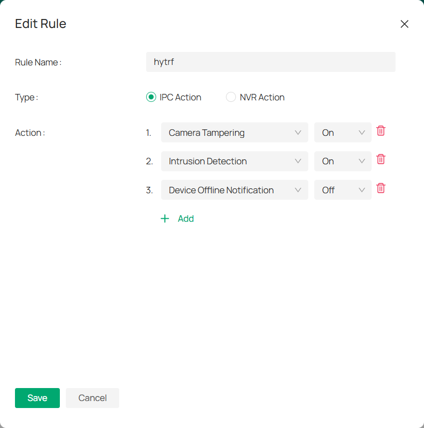
4. Click Save to apply your changes.
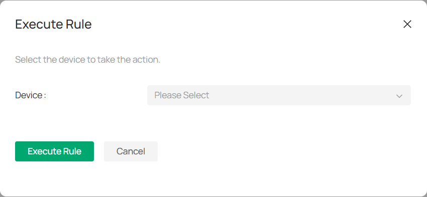
■ Execute Rules
To apply a rule to the selected devices, follow these steps:
1. In the rule list, click ![]()
![]() in the Action column.
in the Action column.
2. On the Execute Rule page, check the box next to the device(s) you want the rule to affect.
3. Click Execute Rule to apply the settings to the selected device(s).
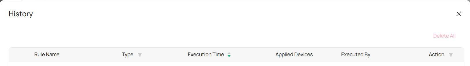
■ View Rules History
Once a rule is executed, a history record is created. You can view this record by following these steps:
1. Click History to open the list of executed rule records.
2. To save the history, click Download to save it in .XLSX format.
3. For more details about a specific rule, click Details to view the rule’s actions and results.
4. If you wish to download multiple history records at once, select the entries you want and click Download, or click Download All to save everything.
7. 2 Device Maintenance
The Device Maintenance feature in VMS allows you to manage tasks related to device upkeep, such as scheduling reboots and configuring rules to automate these processes. This ensures the smooth operation of devices over time without requiring manual intervention.
■ View Device Maintenance Rules
1.To view existing maintenance rules, go to Devices > Device Maintenance.
2.You will see a list of all the scheduled tasks, including the Task Type, Rule Name, Description, Scheduled Time, and the Devices applied to each rule.
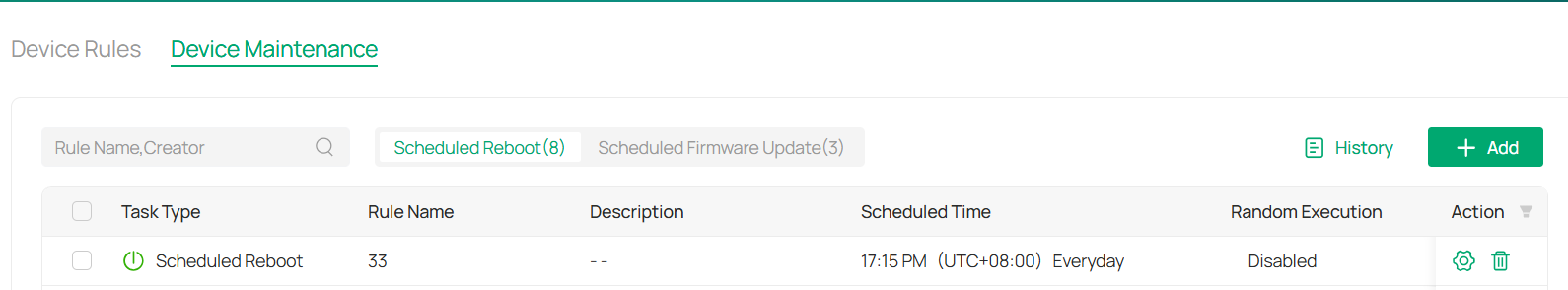
3. You may click 
 to edit the rule or click
 ![]()
![]() to delete it.
to delete it.
■ Add a New Device Maintenance Schedule
To create a new device maintenance rule, follow these steps:
1. Click 
![]() in the top right corner of the Device Maintenance page.
in the top right corner of the Device Maintenance page.
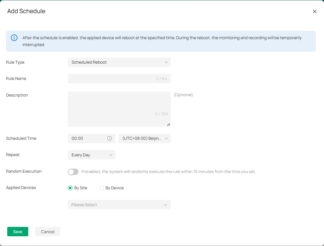
2. In the Add Schedule window, input the required details:
|
Rule Type |
Select the type of maintenance task |
|---|---|
|
Rule Name |
Enter a name for your rule. |
|
Description |
Optionally, provide a description of the maintenance task. |
|
Scheduled Time |
Set the specific time when the device will be rebooted (e.g., 00:00). Ensure the time is set according to your local time zone. |
|
Repeat |
Choose how often the task will be repeated. |
|
Random Execution |
If enabled, the system will randomly execute the rule within 10 minutes from the scheduled time. |
|
Applied Devices |
Choose whether this rule applies to devices by Site or by Device. Select the relevant devices accordingly. |
3. Once all details are filled out, click Save to create the maintenance schedule.
Chapter 8 Applications
The Applications chapter showcases advanced tools that extend the functionality of your VMS beyond basic monitoring. Features such as AI Search, Auto Snapshot, People Counting, Device Map, and the Design Tool provide intelligent analytics, automated insights, and intuitive visualization options—helping you manage devices more efficiently and make data-driven decisions with ease.
8. 1 AI Search
The AI Search feature in the VMS allows users to search for specific events and footage based on human or vehicle characteristics. By leveraging AI-based recognition, you can easily filter video content based on attributes like gender, clothing color, vehicle type, and more. This makes finding relevant footage quicker and more efficient, especially for large-scale surveillance setups.
8. 1. 1 Human Search
■ Search Pictures by Feature
1. Choose the Human tab on the left panel to filter results based on human-related attributes.
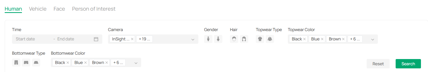
2. Set the following filter conditions:
|
Time |
Set the Time range by selecting the start and end dates to specify when the human-related event occurred. |
|---|---|
|
Camera |
Select the Camera from which the footage was recorded, or choose multiple cameras if needed. |
|
Gender |
Choose the Gender (Male/Female) to filter human recognition results by gender. |
|
Hair Length |
Select options like short, medium, or long. |
|
Top Style |
Select clothing type(s). |
|
Top Color |
Choose the color(s) of the top. |
|
Bottom Style |
Select the style(s) of the bottom wear. |
|
Bottom Color |
Select the color(s) of the bottom. |
3. Click Search to display the relevant results based on your filter settings.
■ Search Pictures by Face
The face recognition feature allows you to search for pictures based on facial attributes. By uploading a photo and filtering by time and camera, you can quickly find instances where a specific face appears within the system’s stored video footage. This is ideal for tracking individuals across multiple cameras and time frames.
1. Click on the Face tab at the top to filter results based on facial attributes.
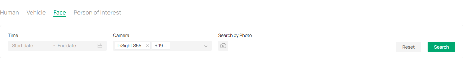
2. (Optional) Attach a profile to find a person.
1) Click Search by Photo.
2) Click to upload or drag a file to the designated area in the pop-up window.
3. Specify the time and camera from which to filter the facial recognition results.
4. Click Search to initiate the search based on the selected filters and uploaded photo.
■ Search Pictures by Identity
The Person of Interest feature enables you to search for pictures based on specific identities. By uploading a person’s photo and defining details like their name, you can set up a profile and search for images associated with that individual. You can refine results by time and camera, and improve accuracy by adding additional photos to the person’s profile for better identification. This feature helps with managing and identifying people across different devices and events.
1. Click on the Person of Interest tab to filter results based on specific identities.
2. Add a new person.
1) Click the + icon.
2) Drag or click to upload a file.
3) Add the person’s name and click Add to save their profile.
3. After the profile is uploaded, click the photo to view or edit the profile.
4. Filter results based on the time and camera that captured the image.
5. (Optional) Click + to upload more photos of the person for better identification.
6. Use the vertical ellipse icon in the lower-right corner of a photo to:
1) Download the photo.
2) Add it to the person’s profile.
3) Report incorrect recognition.
8. 1. 2 Vehicle Search
1. Click the Vehicle tab to search for footage based on vehicle-related characteristics.
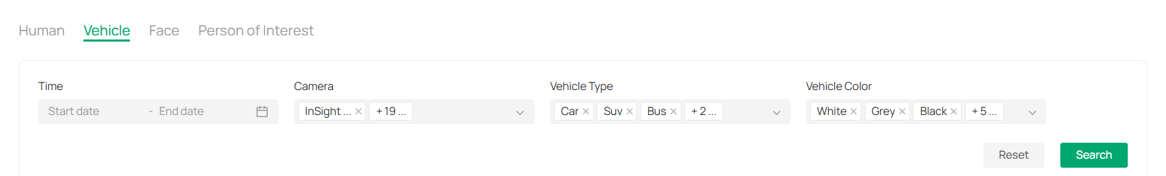
2. Set the following filter conditions:
|
Time |
Select the Time range for when the vehicle-related event occurred. |
|---|---|
|
Camera |
Choose the Camera from which you want to view footage, or select multiple cameras. |
|
Vehicle Type |
Select the type(s) of vehicle. |
|
Vehicle Color |
Select the color(s) of vehicle. |
3. Click Search to process your request and display the relevant vehicle footage.
8. 2 Auto Snapshot
The Auto Snapshot feature allows IP cameras to capture snapshots either instantly or at scheduled intervals. You can use Instant Snapshot to capture images or videos on demand or set up Scheduled Snapshots to automate the process at regular intervals. The tool also provides options for managing snapshot tasks, configuring auto deletion, and reviewing logs and snapshots based on specific criteria.
8. 2. 1 Instant Snapshot
1. Go to Application > Auto Snapshot > Instant Snapshot.

2. Choose the site of your cameras and click Search.
Locate the camera and click on its live view window.
To capture a snapshot, click ![]()
![]() , or click
, or click ![]()
![]() to start recording a video.
to start recording a video.
3. Customize your settings (Optional).
|
Icon |
Function |
Explanation |
|
|
Pause |
Pause the live view. |
|
|
Resolution |
Adjust the image/video resolution. |
|
|
Digital Zoom |
Zoom in on the live view digitally. |
|
|
Smart Frame |
Enable to detect and capture motion, human, or vehicle objects. |
|
|
Sound |
Toggle sound capture on/off. |
|
|
Ratio |
Adjust aspect ratio (e.g., 16:9, 4:3). |
|
|
Full Screen |
Switch to full-screen mode for better visibility. |


8. 2. 2 Scheduled Snapshot
■ Add a Snapshot Task
1. Go to Application > Auto Snapshot > Scheduled Snapshot > Configure Snapshot Scheduler.
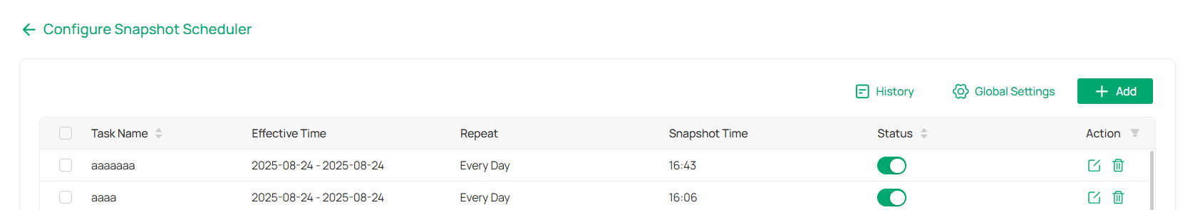
2. Click +Add.
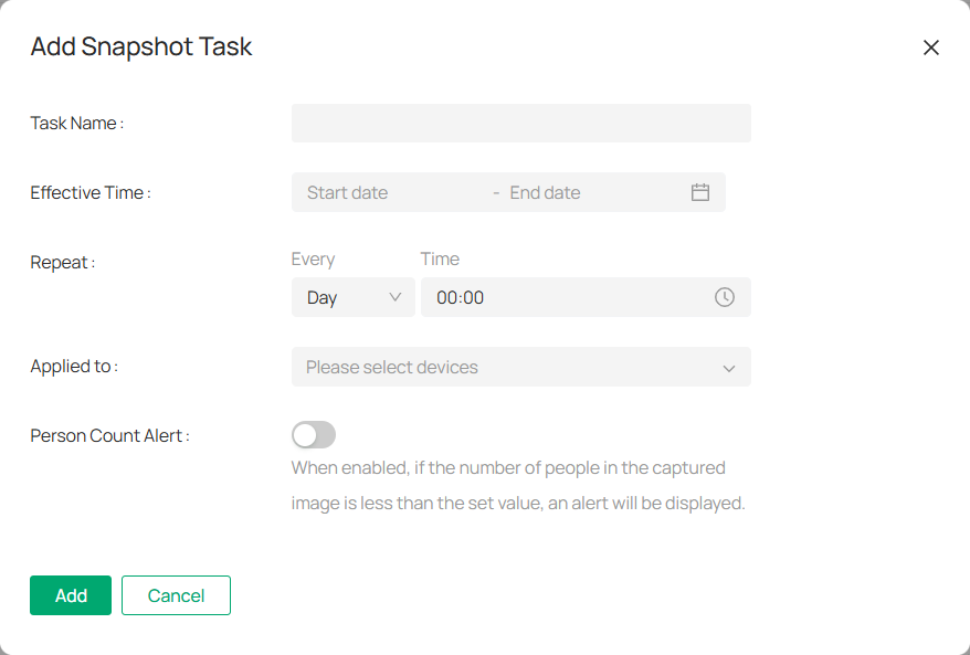
3. Fill in the required information:
Task Name: Enter a task name.
Effective Time: Set the start time and end time for the task.
Intervals: Define how often the snapshot should be captured.
Devices: Choose the devices to include in this task.
4. (Optional) Enable the People Count Alert to trigger notifications when the number of people in the snapshot is below a specified threshold.
5. Click Add to save the task.
6. To edit an existing task, click ![]()
![]() in the action column. To delete a task, click
in the action column. To delete a task, click ![]()
![]() .
.
■ Batch Deletion and Cleanup
1. Go to Application > Auto Snapshot > Configure Snapshot Scheduler.
2. Click Global Settings.

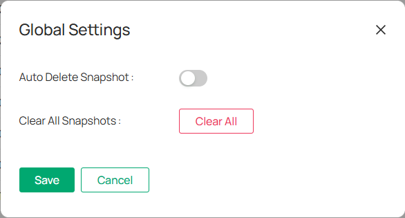
3. Enable Auto Delete Snapshot and set the interval for automatic deletion.
4. (Optional) To clear all snapshots, click Clear All.
■ View and Manage Snapshot Logs
1. Go to Application > Auto Snapshot > Scheduled Snapshot > History.
2. Filter logs by time range, task name, device, and whether the snapshots were successfully taken.
3. Click View or Download to access individual logs.
4. Click 
 to delete or export logs in batches by selecting multiple entries and clicking Delete All or Export All.
■ Search and View Snapshots
1. Go to Application > Auto Snapshot > Scheduled Snapshot.
2. Filter by time range, camera, and task name and click Search.
3. (Optional) From the Exception drop-down menu, select Real-Time Alarm to exclude real-time alarms from your search.
4. Hover over a snapshot and click to:
View it in full screen.
Download the image.
View all snapshots from the same device.
8. 3 People Counting
People Counting allows you to track and count people entering or exiting specific areas, which is useful for various applications such as monitoring foot traffic in retail stores or managing occupancy levels. Ensure that your camera supports the People Counting feature; the supported devices list can be found in the FAQ: How to Configure People Counting on VMS Cloud.
8. 3. 1 Set Up People Counting
1. Go to Application > People Counting > People Counting Quick Settings.
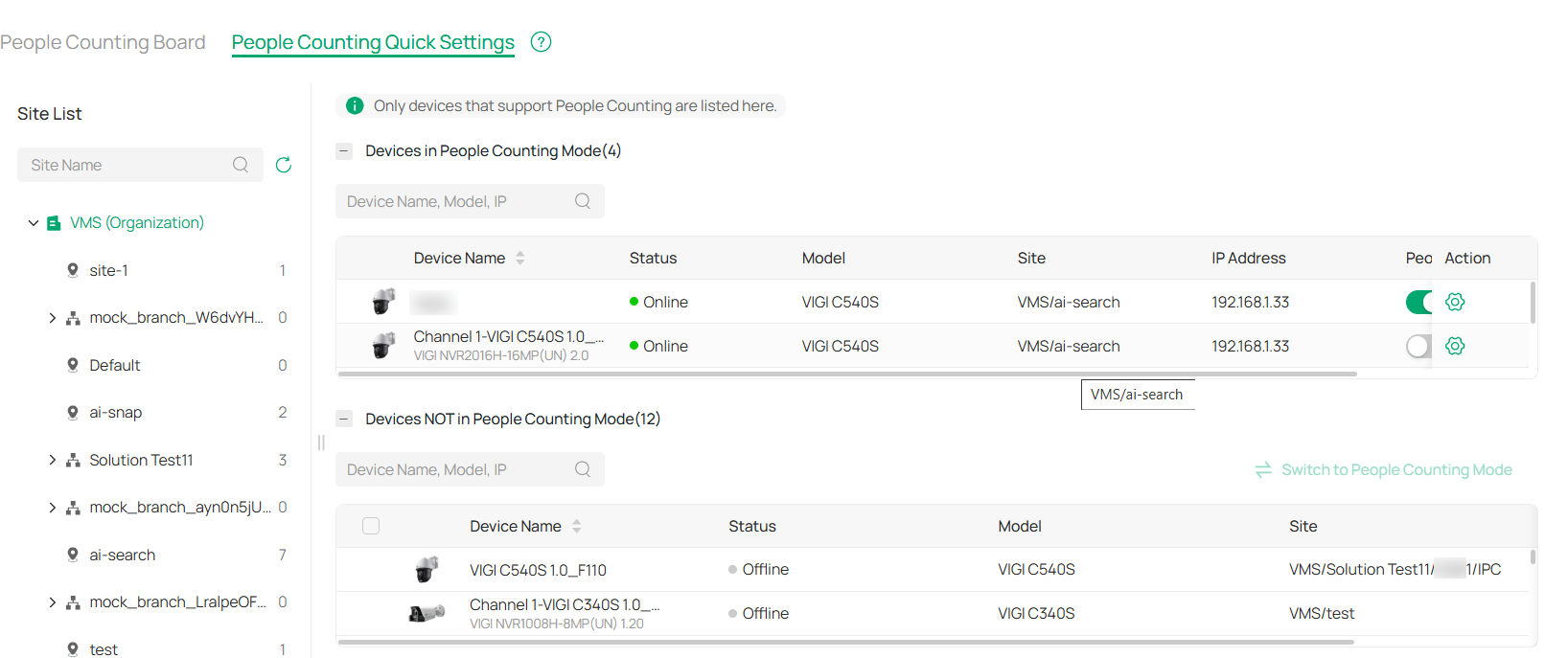
2. Enable or disable People Counting.
Disable People Counting: Find your device in the Devices in People Counting Mode list, and toggle off the People Counting Status.
Enable People Counting: Locate your device in the Devices NOT in People Counting Mode list, check the box, and click Switch to People Counting Mode.
3. To modify people counting parameters, click 
 in the Action column of a device.

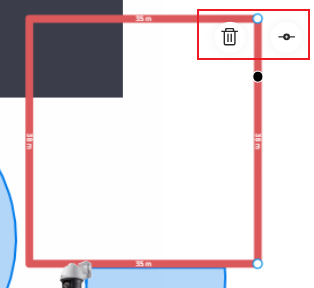
4. Add a monitoring area.
1) Click the + icon at the bottom right of the live view screen.
2) Drag the corners to adjust the size and shape of the area.
3) To set a division line (inside vs. outside), drag the end of the line.
4) Click 
 to remove a specific area.
5) Click 
![]() to remove all areas.
to remove all areas.
5. Use the slider to choose between Low, Medium, or High sensitivity.
Note: High sensitivity detects more movement (potential false positives), while low sensitivity may miss some people but reduce false positives.
6. Configure direction of counting.
Select A→B or B→A to track people entering or exiting an area.
For A→B: A represents the outside and B represents the inside. People moving in this direction are counted as entries, while those moving against this direction are exits.
Passing-by Count: This tracks people appearing in the outside area but not crossing the preset line. The count is used to calculate the entry rate.
7. Set opening hours.
1) Use the time bar to define your desired opening hours.
Note: Each cell represents one hour, and the default is 24/7. You can configure up to six time periods per day.
2) Fine-tune the time periods (Optional). Double-click a time block to open a pop-up window, allowing you to adjust the start time and end time with minute-level accuracy. Click Save.


3) You can also copy the schedule from one day to another by clicking the copy icon next to the time block and selecting the days you want to copy it to.
8. Once all parameters are set, click Apply to save your configuration.
8. 3. 2 Monitor the People Counting Board
1. Go to Application > People Counting > People Counting Board.
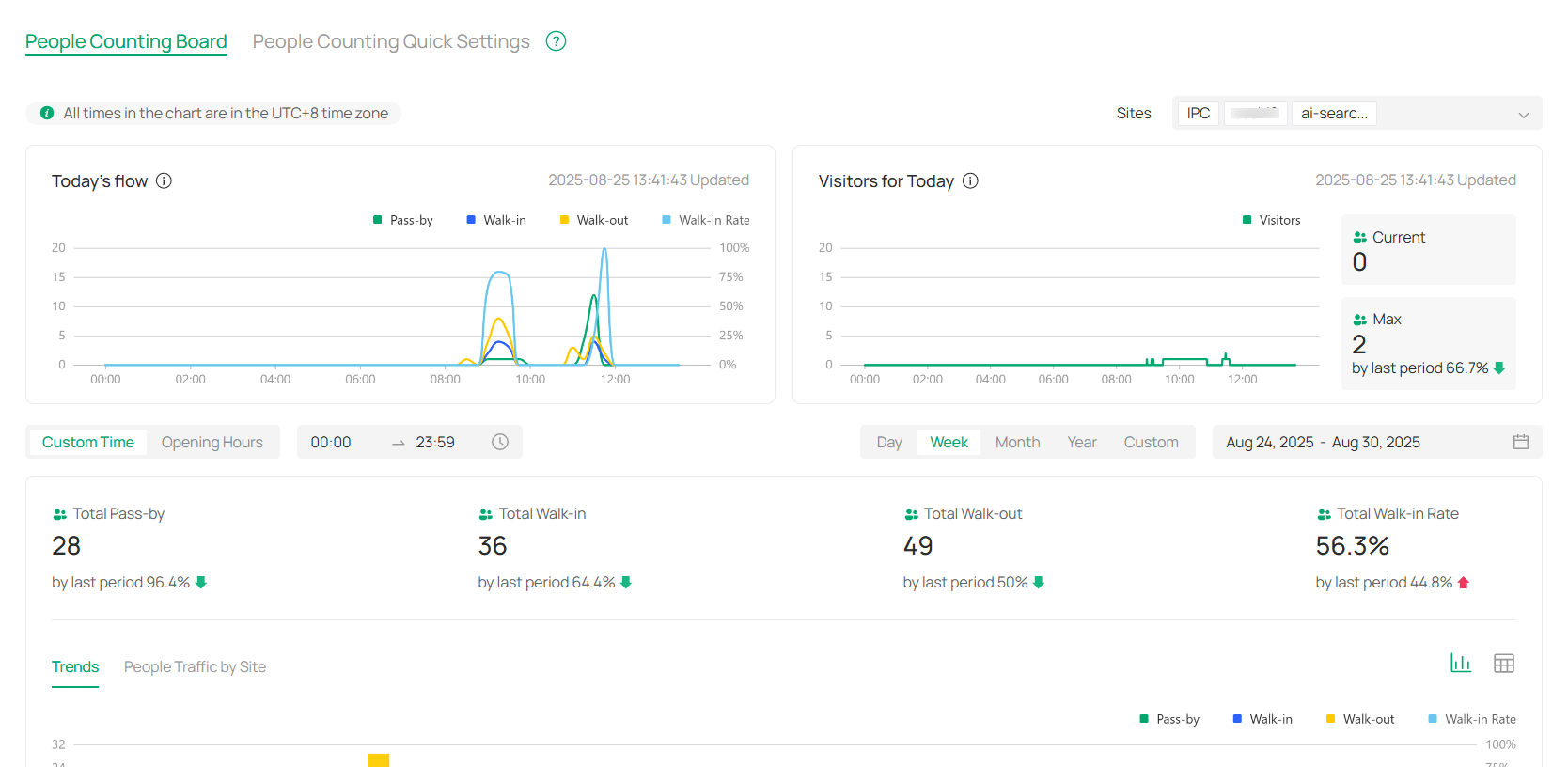
2. Customize your view by selecting specific sites and time periods. You can either choose a predefined time slot, such as opening hours, or manually set your preferred time range. You can view the data by day, week, month, year, or any custom time period.
|
Chart |
Explanation |
|---|---|
|
Today’s Flow |
Displays the distribution of people flow throughout the day. This includes Pass-by, Walk-in, and Walk-out data. The chart also provides the Walk-in Rate as a percentage of the total traffic. Note: The chart is updated in real time, providing immediate insights into the people flow at the selected time period. |
|
Visitors for Today |
Displays the current and maximum number of visitors for the day, as well as a comparison to the last period. This section provides an overview of visitor activity, helping you track peak traffic times. |
|
Trends |
This section highlights the trends in people flow over the selected period. It displays how the number of visitors, pass-bys, and walk-ins changes day by day, offering insights into patterns over time. |
|
People Traffic by Site |
Provides a detailed view of the traffic at each site. This allows you to assess visitor patterns across different locations, helping to understand the flow at each individual site. |
8. 4 Device Map
The Device Map feature in VMS offers a visual representation of where cameras and alarm input devices are situated within your environment. It helps in mapping out the physical locations of cameras, NVRs, and their respective directions. The E-map functionality also allows the organization of devices in hierarchical structures, making it easier to navigate from broad views, like an entire floor, down to specific rooms.
With the Device Map feature, you can search for monitors based on their physical locations and access real-time surveillance footage and alarm events. Key functionalities of the Map include an overview, the ability to add and manage maps, label them, and utilize the Designer Tool.
To access the page, go to Application > Device Map.
8. 4. 1 Add Map
1. Click ![]() or drag your file into the designated area.
or drag your file into the designated area.
Note: The system accepts various formats, including PDF, PNG, JPG, JPEG, BMP, SVG, and DXF.
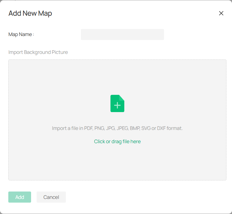
2. Once the file is uploaded, you can preview the map. If you need to upload a different file, click Reupload.
3. Enter a name for your map and click Add.
Note: The system allows for the uploading of multi-page PDF files, and you can choose a specific page for previewing and adding.
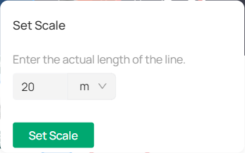
4. (Optional) Edit the map scale.
The map scale defines the relationship between the distance shown on the map and the actual distance on the ground.
To set the scale, adjust the line segment by dragging the two dots shown, or input the actual length of the line. Click Set Scale.

8. 4. 2 Manage Map
You can manage your maps with options to zoom in, zoom out, adjust layers, and generate heatmaps.
|
Icon |
Name |
Explanation and Operation |
|---|---|---|
|
|
Fit to Extent |
Click to automatically resize the map, showing all active devices and camera placements in one unified view. |
|
|
Zoom In/Out |
Adjust the map’s level of detail. You can also use the scroll wheel on your mouse for smoother zoom adjustments. |
|
|
Layer |
Click the Layer icon to reveal or hide specific layers. Check or uncheck the options to customize the map display according to your needs. Labels: Show device names on the map for easier identification. People Counting: Track and display people counting data, useful for areas with a lot of foot traffic. Monitoring Areas: Highlight specific zones that are under surveillance. People (Beta): If enabled, it shows detected people in various locations on the map. |
|
|
Heatmap: People |
Click to a view heatmap that visualizes the intensity of activity or movement within various areas over a defined period. It’s especially useful for identifying high-traffic zones. |
 |
Heatmap Settings |
Click to select your desired time frame (e.g., Recent 1 Hour, Recent 3 Hours). |


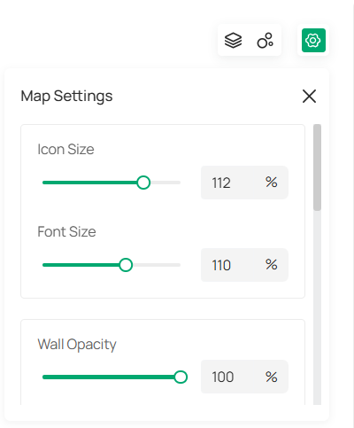
You can click  to customize the appearance and layout of your map, making it easier to adapt to your specific monitoring needs. Below are the settings you can adjust:

|
Icon Size |
Adjust the size of the icons displayed on the map. |
|---|---|
|
Font Size |
Change the size of text displayed on the map, such as device names or labels. Increase the size for better readability, or reduce it to fit more text. |
|
Wall Opacity |
The Wall Opacity slider controls the transparency of walls on your map. |
|
Wall Thickness |
Adjust the width of the wall lines on your map. |
|
Wall Color |
Choose a color for the walls of the map by selecting one from the color options. |
|
Map Name |
Change this name to better organize and label your maps. |
|
Floor Plan Opacity |
Adjust the transparency of the floor plan. Lower opacity allows for a clearer view of overlaid elements like cameras and devices. |
|
Edit Scale |
Click to modify the scale of your map, ensuring accurate representation of real-world distances. |
|
Change Map |
Select to upload a new map if needed. |
|
Add Sub Map |
If your map contains multiple levels (e.g., different floors), use this option to add a sub-map. |
|
Clear All Markers |
Use this option to remove all markers from the map, which helps reset your view. |
|
Delete Map |
Click to permanently delete the map from the system. |
8. 4. 3 Manage Hot Spots
The markers added to the map are called hotspots. These hotspots not only indicate the locations of the devices but also provide live views and alarm details related to surveillance activities.
You can add labels to describe locations, create links to navigate to other maps, and include devices to monitor the online status of connected IPCs and NVRs. Additionally, you can view the monitoring range of IPCs and access real-time previews.
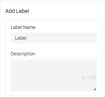
■ Add Labels
To add a label to a specific location on the map, follow these steps:
1. In the Edit page, click 
 in the top right corner of the screen.
2. Move your mouse cursor to the desired location on the map where you want to place the label. Once the location is selected, click on it.
3. In the pop-up that appears on the right, enter a name for the label. You can also add a description (optional) for more context.
4. Click Create.

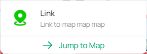
■ Add Links
You can add links to locations on the map and navigate to other maps.
To add a label to a specific location on the map, follow these steps:
1. In the Edit page, click 
 in the top right corner of the screen.
2. Move your mouse cursor to the desired location on the map where you want to place the label. Once the location is selected, click on it.
3. In the pop-up that appears on the right, enter a name for the link and select a map.

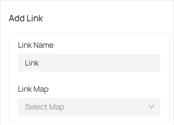
4. Click Create.
5. Once the link is created, hover your cursor over the icon, and a pop-up window will appear. Click on Jump to Map to view the map associated with this link.

■ Add Devices
Follow these steps to add a device:
1. On the Edit page, click 
 .
.
2. In the pop-up window on the right, select the device from the organization and site.

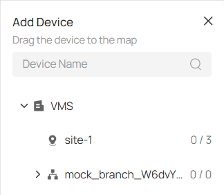
3. Drag the device to the map and click it to place the marker at your desired location. You may click  and drag the colored area to adjust the surveillance angle and coverage.

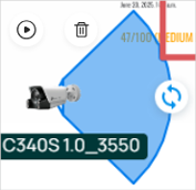
4. Click on the device marker, then click ![]() view the real-time monitoring feed.
view the real-time monitoring feed.

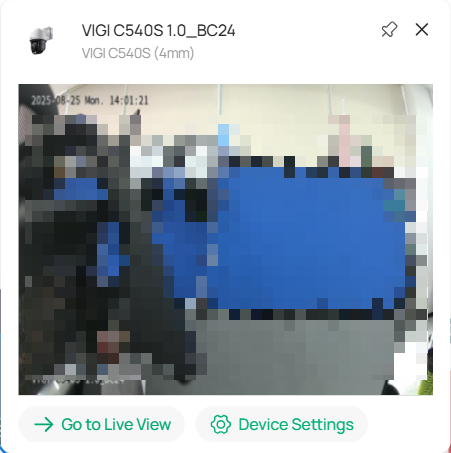
5. To access the Video page, click Go to Live View in the pop-up window. For more detailed parameters, click Device Settings.
6. Click the device marker and you can configure parameter settings.

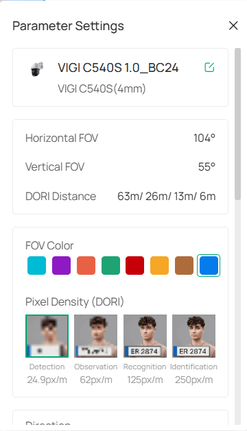
|
Device Name |
Enter the name of the device.. |
|---|---|
|
Model |
Specifies the model number of the camera. |
|
Horizontal FOV |
Displays the horizontal field of view of the camera (measured in degrees). |
|
Vertical FOV |
Displays the vertical field of view of the camera (measured in degrees). |
|
DORI Distance |
Defines the distance (in meters) at which the camera can detect, observe, recognize, and identify objects. |
|
Mounting |
Select from the drop-down menu how the camera is physically set up. |
|
FOV Color |
Select a color from the available options for the field of view to be represented in the map. |
|
Pixel Density (DORI) |
It represents the pixel density for different detection ranges: Detection, Observation, Recognition, and Identification. Choose the appropriate pixel density based on the range requirements of the surveillance task. |
|
Direction |
Specify the camera’s orientation. |
|
Installation Height |
Set the height of the camera from the ground. |
|
Distance to Target |
Adjust the distance between the camera and the target object |
|
Target Height |
Adjust the height of the object or area being monitored. |
|
Tilt Angle |
Change the vertical angle at which the camera is pointed. |
|
Blind Spot |
View the blind spot area in 3D view or in a large picture. |
8. 4. 4 Draw Rooms or Walls
To define walls on the map that block the camera’s viewing angle, follow these steps:
1. Click ![]()
![]() , and then click
, and then click ![]() in the upper right corner of the screen.
in the upper right corner of the screen.
2. Select Draw Wall. Click on the map and drag your mouse to form a line.
Note: Click the map first and then drag your mouse.
3. Or you may select Draw Room. Click on the map and drag your mouse to form a rectangle.
4. To split an existing wall, click on the wall and then click ![]()
![]() to divide it into two parts.
to divide it into two parts.

5. To delete a wall, click on the wall and then click ![]()
![]() .
.
6. To modify the wall, click on the corner, intersection, or division point of the wall. Drag your mouse to adjust the size, length, or orientation of the wall to fit your desired layout.
8. 4. 5 Setting Up People Counting with Virtual Cameras
1. Click ![]()
![]() on the upper right of the map.
on the upper right of the map.
2. In the Add People Counting window, select your camera models and click Create.
Note: This feature is only supported by cameras that enable cross-line counting. If your camera doesn’t support this, go to Device Management to enable the cross-line counting function for the selected camera.

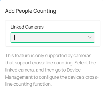
3. Drag the virtual cameras to your desired spot on the map.
8. 5 Design Tool
The Design Tool is an intuitive feature that simplifies the process of planning and managing security system projects. It lets you easily create and customize floor plans, configure devices, and estimate storage and bandwidth needs. With easy-to-use tools for device placement, bulk configuration, and proposal generation, the Design Tool streamlines project setup, helping you quickly bring your security systems to life with precision and ease.
8. 5. 1 Add a Project
1. Go to Application > Design Tool. To create a new project, click ![]()
![]() in the upper-right corner. In the pop-up window, fill in the following details and click Add:
in the upper-right corner. In the pop-up window, fill in the following details and click Add:
Project Name: Enter a unique name for your project.
Scenario: Select a scenario (e.g., General, Hotel, Restaurant).
Description (Optional): Provide a brief description for the project.
Visibility: Choose whether the project should be visible to all organization users or only to you.
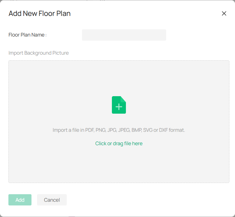
2. After creating the project, click Add New Floor Plan within your project.
1) Enter the Floor Plan Name, then click the designated area or drag and drop a picture into the upload zone.
2) Click Add to save the floor plan.
3. Add devices to the floor plan.
1) On the floor plan page, click ![]()
![]() .
.
2) In the pop-up window, click ![]()
 to choose a camera or NVR (you can filter by device type).
3) Once selected, click on the map to position the device at the desired location.
4. Draw walls on the floor plan manually or using AI detection.
1) Click 
![]() .
.
2) Select among the following:
AI Wall: Automatically detects and adds walls to your floor plan.
Draw Room: Draws the outline of a room.
Draw Wall: Adds a specific wall.
Draw Cylinder: Adds a cylindrical object.
3) Customize the wall’s opacity, thickness, and color as needed.
5. (Optional) Click ![]()
![]() to select the elements you want to display on your floor plan, such as labels, monitoring areas, walls, text, and devices.
to select the elements you want to display on your floor plan, such as labels, monitoring areas, walls, text, and devices.
6. To switch between projects or floor plans, select the one you want to edit from the dropdown menus on the upper left. For detailed configuration, click 
 .
.
You can adjust icon size, font size, wall properties, floor plan name, and background image. You may also add sub-floor plans or clear all markers.
8. 5. 2 View Device List
The Device List allows you to manage your cameras, NVRs, and any accessories or additional fees associated with your project. Follow the steps below to configure and manage your devices.
1. On the floor plan page, go to 
 to view and manage the devices in your project.
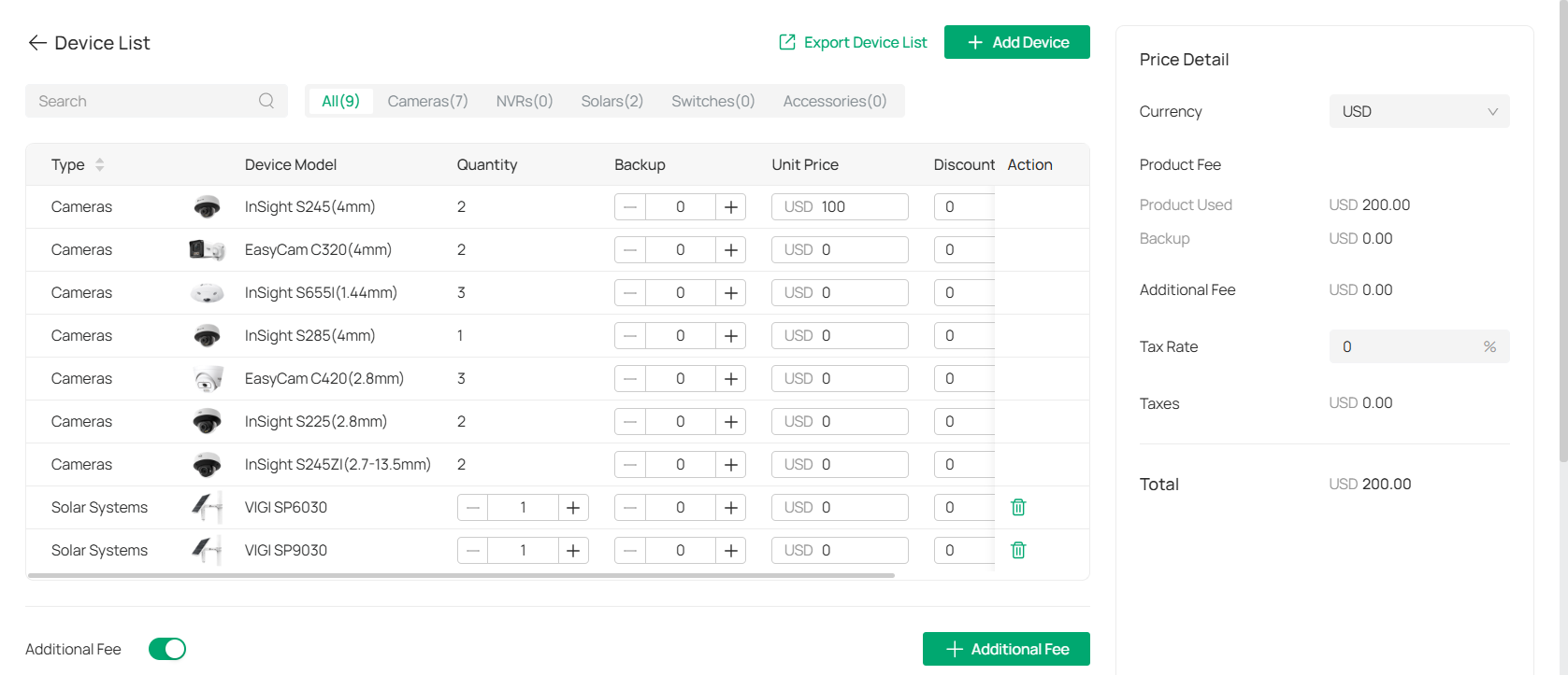
The Device List displays all your devices, including cameras, NVRs, and accessories.
2. Add a new device.
1) Click  . From there, you can select the type of device (e.g., camera, NVR) and enter its details.
2) Click Add.
3. Specify the quantity of cameras and their backups, and the unit price and applicable discounts in the table.
|
Quantity |
The number of units for each device. You can adjust the quantity by clicking the + or - buttons. |
|---|---|
|
Backup |
Assign backup for each device. This can be left at 0 or adjusted as necessary. |
|
Unit Price |
Enter the price of each device. Prices can be modified if needed. |
|
Discount |
Enter any applicable discounts for the device. Default is 0%. |
|
Action |
Edit or remove a device from the list. |
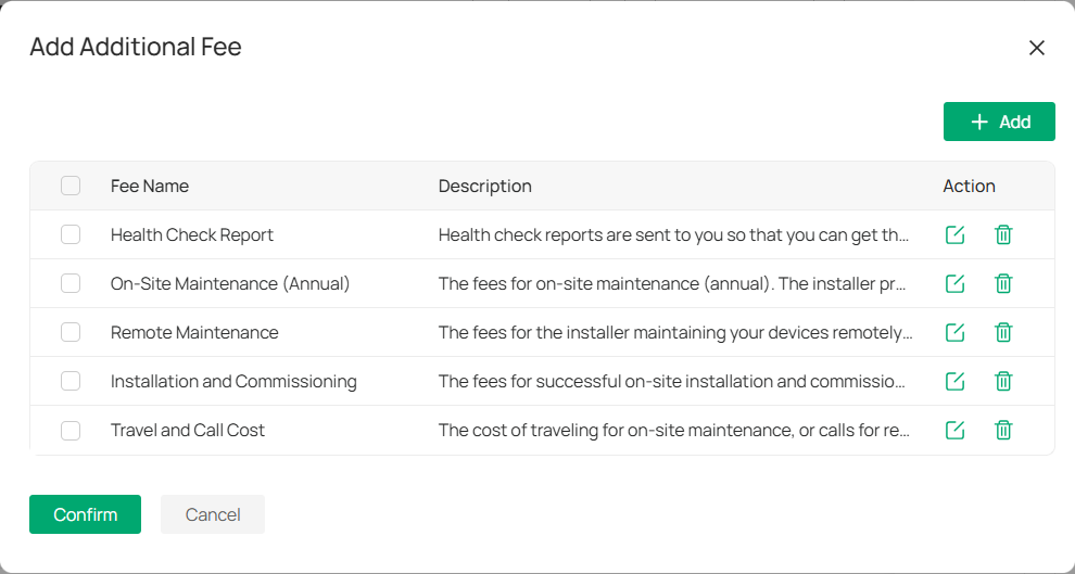
4. Under Additional Fee, toggle on the switch and click  to apply any additional charges related to the device or project. You can customize the fee amount as needed.
5. View price details on the right panel and set the tax rate (if applicable).
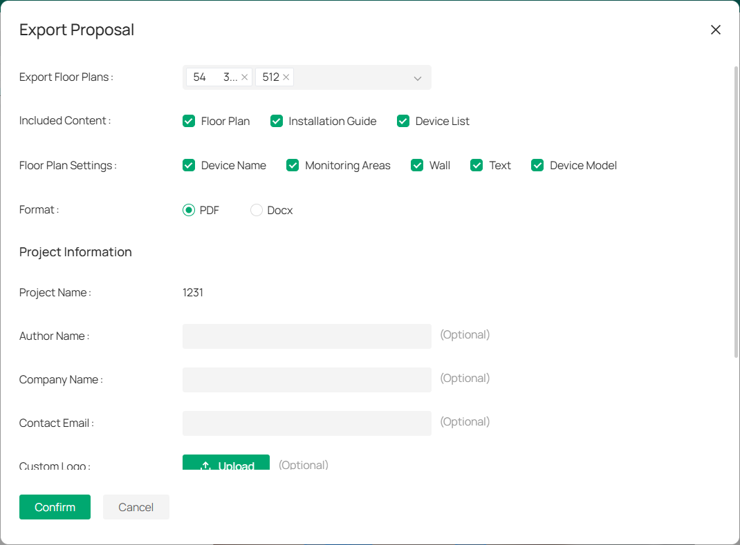
8. 5. 3 Export Your Proposal
To export a project proposal based on your design plan, follow the steps below:
1. Navigate to the floor plan and click the ![]() icon.
icon.
2. Complete the required fields:
|
Export Floor Plans |
Select the floor plans to include in the proposal. |
|---|---|
|
Included Content |
Choose what to include in the proposal, such as, Floor Plan, Installation Guide, and Device List. |
|
Floor Plan Settings |
Select the items to include on the floor plan, such as, Device Name, Monitoring Areas, Wall, Text, and (Optional) Device Model. |
|
Format |
Choose the proposal format (PDF or Docx). |
|
Project Information |
Provide the project name, author name, company name, contact email, and optionally upload a custom logo (note: file size must be under 2MB). |
|
Watermark |
You can toggle the watermark option on or off (e.g., “VIGI Design Tool”). |
3. After filling out the necessary fields, click Confirm to generate the proposal.
8. 5. 4 Managing Floor Plans
The floor plan interface allows you to effectively manage your devices and plan configurations. Below are the key actions and tools available for use:
■ Adding Labels, Links, and Devices
To add labels, links, and devices, refer to the section Manage Hot Spots.
■ Place Text
Text annotations allow for additional information to be displayed on the floor plan:
1. Click ![]()
![]() .
.
2. Click the map at the location where you want the text to appear.
3. Enter the text in the pop-up field and click elsewhere to add it.
■ Use the Calculator Tool
The Calculator tool is essential for estimating storage, bandwidth usage, and storage time based on your device setup.
1. Click ![]()
![]() . In the Calculator window, the system will automatically display the number of Cameras, NVRs, and HDD Slots based on your floor plan configuration. Ensure that the counts are accurate for your setup.
. In the Calculator window, the system will automatically display the number of Cameras, NVRs, and HDD Slots based on your floor plan configuration. Ensure that the counts are accurate for your setup.
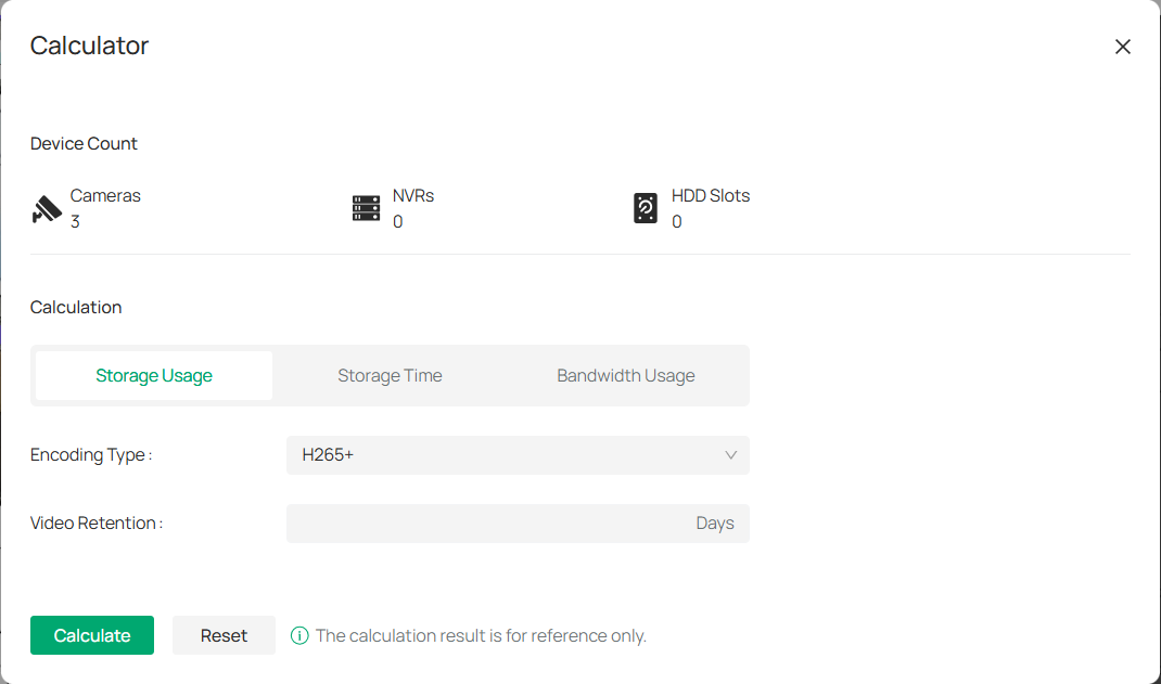
2. Select the Calculation Type: Choose one of the following options:
1) Storage Usage: Estimate how much storage is needed for your devices.
2) Storage Time: Determine how long your video footage can be stored given the available storage space.
3) Bandwidth Usage: Estimate the bandwidth required for your devices based on encoding and retention settings.
3. Configure the following:
|
Encoding Type |
Select the video encoding type used by your cameras. For most systems, the default is H265+, but you can adjust it based on your configuration. |
|---|---|
|
Video Retention |
Enter the retention period in days (the number of days you wish to store video footage). |
|
HDD Volume |
If calculating storage or storage time, enter the hard disk drive volume (in TB or GB) that you have available for storage. |
4. Once all fields are filled out, click Calculate to see the estimated results.
Note: The calculator provides rough estimates to assist with planning, but the results are for reference only.
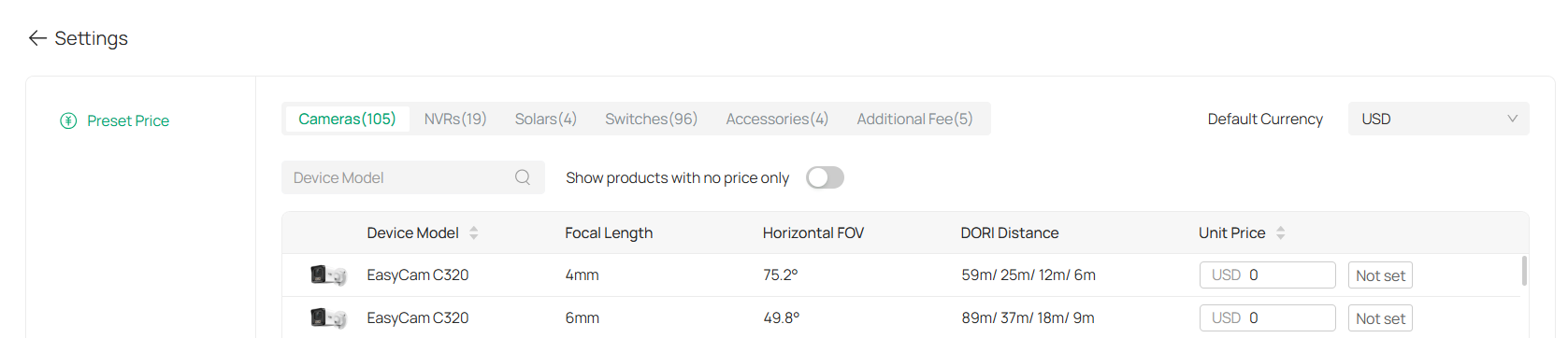
8. 5. 5 Settings
The Settings section in the Design Tool allows you to manage and customize the details of your devices, such as camera models, focal lengths, field of view (FOV), and pricing. This section helps ensure that all the devices in your system are configured correctly and that the necessary information is up-to-date.
1. To access the Settings menu, go to Application > Design Tool > Settings.
2. Once in the Settings section, you can manage the following details for each device:
|
Device Model |
Displays a list of all available camera models. |
|---|---|
|
Focal Length |
Shows the camera’s focal length, which affects its zoom and field of view. |
|
Horizontal FOV (Field of View) |
Indicates the camera’s horizontal field of view, which determines the coverage area. |
|
DORI Distance |
Stands for Detection, Observation, Recognition, and Identification distances. These represent the ranges at which the camera can perform these specific actions at different levels of detail (e.g., detecting motion, recognizing faces). |
You will also see the Unit Price column, where you can set the price for each device.
3. To make it easier to find the devices you want to modify, use the search bar to filter by Device Model or adjust the displayed list by selecting Show products with no price only.
4. For devices that require a price, you can set the price by typing it in the Unit Price column for each device. If no price is set, the column will display “Not set.”
5. Click Apply at the bottom to save your settings.
8. 5. 6 Viewing and Managing Projects
The Projects page in the Design Tool provides an organized overview of all your active projects, making it easy to navigate, filter, and perform actions on each project.
Go to Application > Design Tool.
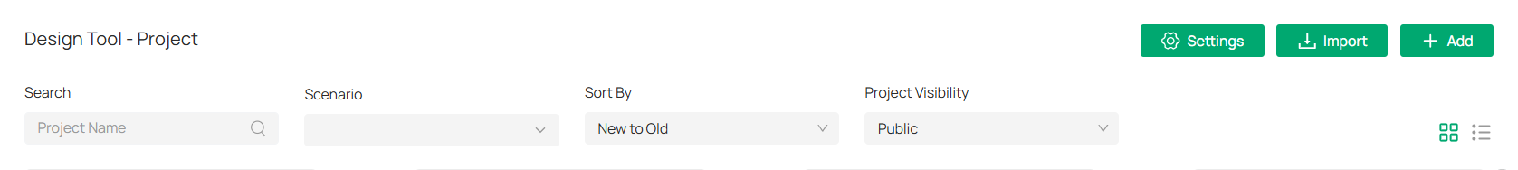
1. The Projects page offers several filtering options to help you locate specific projects quickly:
Search: Enter the project name in the search bar to find a specific project.
Scenario: Filter projects based on the scenario (e.g., retail, hotel, or office).
Sort By: Choose how to sort projects, either by newest to oldest or oldest to newest.
Project Visibility: Select whether to display public or private projects.
These filters help narrow down large project lists to quickly find what you need.
2. Projects can be displayed in two modes:
Thumbnail View: A visual representation of each project, showing a preview of the floor plan and basic details.
List View: A detailed table view that shows project names, the number of floors, devices, and last updated time.
You can switch between these two views by selecting respective icons 
 in the top-right corner.
3. For each project, you can perform several actions by clicking ![]()
![]() located to the right of the project name. Available options include:
located to the right of the project name. Available options include:
Edit: Make changes to the project details, such as updating the project name, adding devices, or adjusting floor plans.
Publish Proposal: Generate and publish the proposal for the selected project.
Export: Export the project’s details or floor plan to a file format (e.g., PDF, Docx).
Duplicate: Create a copy of the project for further customization or to serve as a template.
Delete: Remove the project permanently from the system.
Chapter 9 Change Camera Settings
This chapter guides you on how to change the settings of your monitoring devices via VIGI VMS.
To change device settings, go to Devices.
Choose the site where your device is located, find your device in the list, and click 
 . The parameters to modify include Device Name, Local Upgrade, Video Settings, Smart Event, System Management, Network Settings.
9. 1 Information
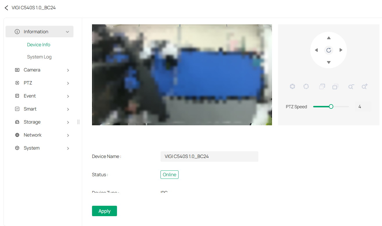
9. 1. 1 Device Information
You can view basic information about the camera, including device name, status, device type, model, hardware and firmware version, device ID, IP address, MAC address, resolution, frame rate, and device time.
1. Go to Devices, choose the site where your device is located, find your device in the list, and click 
 .
.
2. In the panel that appears on the right, head over to Information > Device Info.
3. You may edit its name in the Device Name field and click Apply.
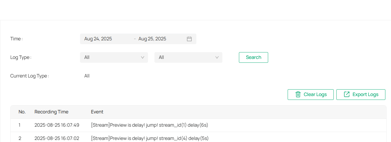
9. 1. 2 System Log
The camera uses logs to record, classify, and manage system and device messages. You can search, view, and export the logs.
1. Go to Devices, choose the site where your device is located, find your device in the list, and click  .
.
2. In the panel that appears on the right, head over to Information > System Log.
3. Specify search conditions, including the Start Time, End Time, and Log Type, and click Search. The filtered logs that match the search conditions will appear in the table.
|
Start/End Time |
Specify a time range to filter the logs based on the recording time. |
|---|---|
|
Log Type |
Select a type from the drop-down list to filter the logs. All: All types of logs. Alarm: Alarms triggered by events, such as tampering, line crossing, and area intrusion. Exception: Abnormal events that may influence the camera’s functions, such as video signal loss and hard drive errors. Operation: Actions that take place on the camera, such as login and upgrade. Information: Informational messages, such as device information. |
|
Clear Logs |
Click to delete all logs. |
|
Export Logs |
Click to save log files to your computer. |
9. 2 Camera Display Settings
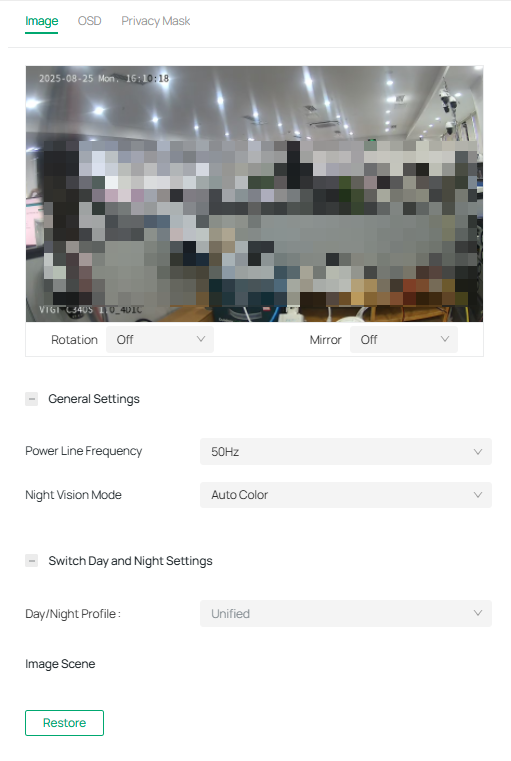
9. 2. 1 Image
You can adjust various image settings of your network camera to optimize video quality for different environments. You can modify parameters such as brightness, contrast, sharpness, exposure, and more, as well as configure advanced features like Day/Night switching, infrared light sensitivity, and white balance, Use these settings to fine-tune the camera’s performance based on lighting conditions and specific monitoring needs.
1. Go to Devices, choose the site where your device is located, find your device in the list, and click 
 .
.
2. In the panel that appears on the right, head over to Camera > Display > Image.
3. Configure the following parameters.

|
Rotation |
Choose to turn the live view image by 0, 90 or 270 degrees on your display. When you select Off, the image displays normally. |
|---|---|
|
Mirror |
Select the mirror mode as needed. When you select Off, the image displays normally. By choosing Left-Right, you mirror the image on the vertical axis. By choosing Up-Down, you flip the image on the horizontal axis. By choosing Center, you rotate the image by 180 degrees around its center. |
|
Day/Night Switch |
Select a method to switch the image settings of day and night. Unified: The camera applies the same image settings throughout a day. Scheduled: The camera switches the image mode of day and night at your specified time. If you select this method, adjust the slide bar to specify the switch time.
Auto: The camera switches the image mode of day and night automatically according to the light condition of the environment. |
|
Brightness |
Increasing the value will lighten the image. |
|
Saturation |
Increasing the value will enrich the color of the image. |
|
Contrast |
Increasing the value will increase the difference between the brighter and darker parts. |
|
Sharpness |
Increasing the value will sharpen the image. |
|
Infrared Light |
Select a mode to decide the usage of white supplement light. The available options vary due to the mode set in Night Vision Mode and Day/Night Switch. Auto: The camera turns on the white light once it detects the environment gets dark, and keeps the light off in a sufficiently lit environment. You can customize the values in Sensitivity and Delayed Switch. Scheduled: Specify the time to turn on and off the white light. Always On/Off: The white light is on/off all the time. |
|
Sensitivity |
Decide the ambient light intensity that can trigger the switch of the white light. The lower the value is, the easier it is to trigger the white light. |
|
Delayed Switch |
Decide how long the camera waits to turn on or off the white light when the ambient light reaches the threshold to trigger the switch. |
|
Prevent overexposure to infrared light |
Select the standard mode or enhanced mode or manually adjust the brightness of image. Standard Mode: In this mode, the brightness of the infrared light will be automatically adjusted to prevent overexposure. The brighter the environment, the dimmer the infrared supplement light. Enhanced Mode: This mode intensifies its protection against overexposure, by darkening the bright areas of the image. Manual: Manually adjust the brightness of image. The higher the value is, the dimmer the image gets. |
|
WDR |
WDR (Wide Dynamic Range) can improve the image quality under high-contrast lighting conditions where both dimly and brightly lit areas are present in the field of view. If you select On, the camera balances the light of the brightest and darkest areas automatically. You may set the gain value, or the sensor’s sensitivity, manually. |
|
BLC Area |
BLC (Backlight Compensation) optimizes the camera to increase light exposure for darkened areas and helps you to see details more clearly. Select an area to compensate light. If you select Custom, draw a blue rectangle on the live view image as the BLC area. |
|
HLC |
HLC (Highlight compensation) can compensate for brighter parts of your image, maintaining detail in brighter parts of the image that would otherwise be blown out. |
|
White Balance |
White balance is a process of removing unrealistic color casts, so that objects which appear white in person are rendered white in the image. Auto: The camera adjusts the color temperature automatically. Locked: The camera keeps the current color settings all the time. Daylight/Natural Light/Incandescent/Warm Light: The camera adjusts the color temperature to remove the color casts caused by the corresponding light. Custom: Drag the slide bar to configure the color temperature, and the camera keeps the settings all the time. You may specify the red/blue gain values separately. The higher the value is, the more intense the red/blue color is. |

9. 2. 2 OSD
The OSD (On-Screen Display) settings interface allows you to customize the information displayed on the camera feed. You can choose to display key details such as the date, day of the week, and channel name directly on the video stream. Additionally, you can adjust the display effect, including transparency and font size or color, to suit your preferences. This feature enhances video monitoring by providing relevant information without interrupting the live view, offering flexibility in how data is shown on-screen.
Follow the steps below to configure OSD settings.
1. Go to Devices, choose the site where your device is located, find your device in the list, and click .
2. In the panel that appears on the right, head over to Camera > Display > OSD.
3. Configure the following parameters, and click Apply to save your settings.

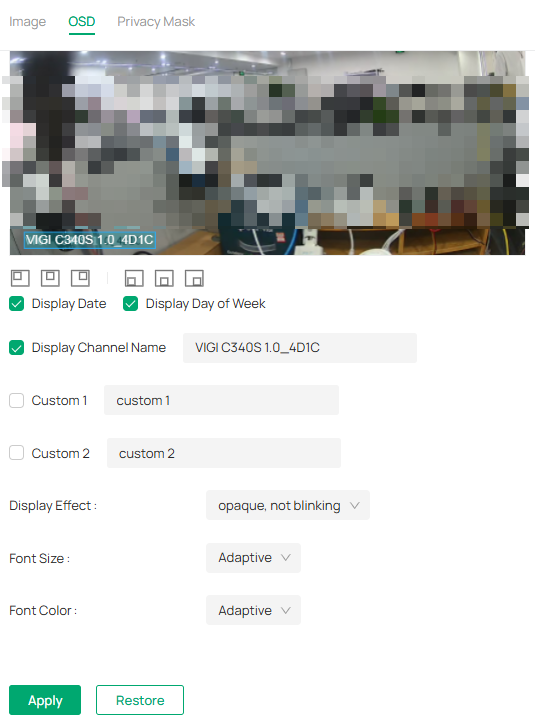
|
Display Date |
Check the box to display the current date on the camera feed. |
|---|---|
|
Display Day of the Week |
Check the box to display the current date on the camera feed. |
|
Display Channel Name |
The camera’s channel name can be displayed on the screen for easy identification. This option is enabled by default. |
|
Custom Labels |
You can add up to two custom labels (Custom 1 and Custom 2) by entering the desired text in the fields. This is useful for specific identifiers. |
|
Display Effect |
Choose the display effect for the on-screen text. |
|
Font Size |
Set the font size. You may select “Adaptive” to automatically adjust the font size based on the screen resolution or manually set the desired font size. |
|
Font Color |
Set the font color. You may choose “Adaptive” for the camera to automatically adjust the font color, or select a specific color for customization. |
|
Restore |
Click to revert to factory default settings. |
9. 2. 3 Privacy Mask
Privacy Mask hides parts of the image from view, ensuring your privacy by preventing these areas from being recorded or monitored.
Follow these steps to configure the Privacy Mask:
1. Go to Devices. Select the site where your device is located, find the device in the list, and click .
2. In the panel that appears on the right, head over to Camera > Display > Privacy Mask.
3. Enable Privacy Mask. Draw the desired privacy area on the preview screen (represented by the blue square in the image below). You can adjust the size and position by dragging the area. For the Mask Type, you can select either Solid Black or Mosaic to control the display effect of the masked area.
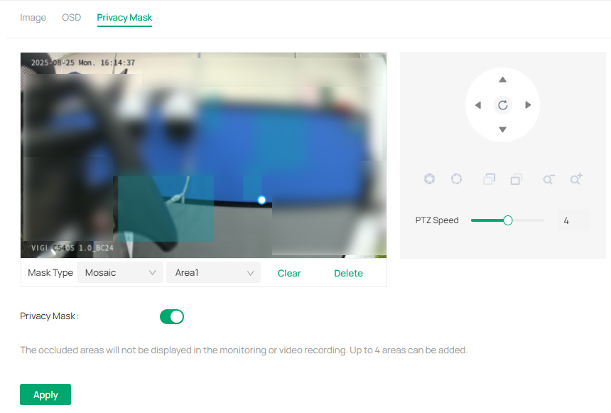
4. To remove a specific privacy area, select it and click Delete.
5. To remove all privacy areas, click Clear.
6. Click Apply.
9. 3 Camera Stream Settings
In Stream Settings, you can configure video stream levels, change the audio output settings and ROI (Region of interest) level.
Video stream levels decide the video quality in Live View and recording, and you can adjust the video quality of certain area by specifying the ROI level.
9. 3. 1 Video
Follow the steps below to configure video settings.
1. Go to Devices. Select the site where your device is located, find the device in the list, and click .
2. In the panel that appears on the right, head over to Camera > Stream > Video.
3. Configure the following parameters, and click Apply.

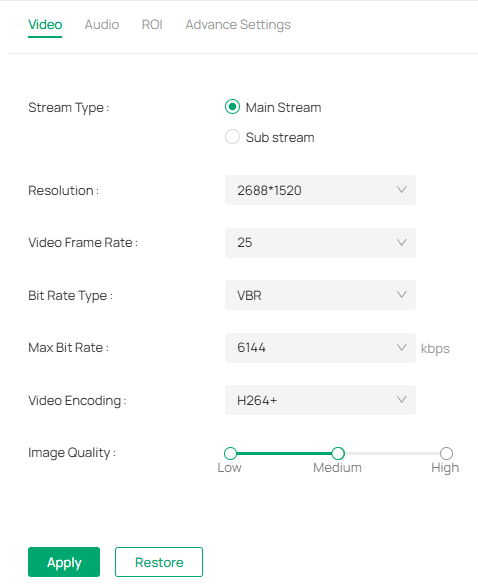
|
Stream Type |
Main Stream is the primary video feed used for recording and provides the highest video quality. It has higher definition and higher bandwidth than sub-stream. Sub-stream is a secondary video feed that is used mainly for remote viewing from computers from outside the network. |
|---|---|
|
Resolution |
The screen displays images more clearly when the resolution increases. |
|
Video Frame Rate |
The video is more fluent when the rate increases. |
|
Bite Rate Type |
VBR: The bit rate changes with the image within Maximum Bit Rate. CBR: The bit rate is Maximum Bit Rate all the time. |
|
Max Bit Rate |
Specify the upper limit of bit rate. |
|
Video Encoding |
Select the encoding type of the stream. H.265 reduces the file size and saves the bandwidth better than H.264. |
|
Image Quality |
When VBR is selected as the Bit Rate Type, set the video quality as high, medium, or low. |
|
Restore |
Click to revert to factory default settings. |
|
Copy to Other Devices |
Use this option to apply these settings to other devices in your system. |
9. 3. 2 Audio
Follow the steps below to configure video settings.
1. Go to Devices. Select the site where your device is located, find the device in the list, and click .
2. In the panel on the right, go to Camera > Stream > Audio.

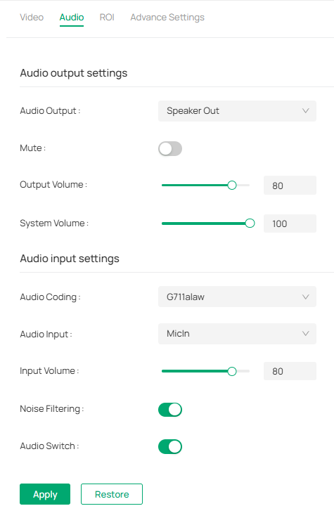
|
Audio Output |
Choose the desired audio output option. |
|---|---|
|
Mute |
Toggle to turn the audio on or off. When enabled, it silences the output. |
|
Output Volume |
Adjust the volume of the audio output by moving the slider. |
|
System Volume |
This controls the overall system’s audio level. The higher the setting, the louder the system’s audio will be. |
|
Audio Coding |
Select an audio encoding type. Audio Coding is the process of converting analog audio into digital data by compressing it for efficient storage or transmission. The default option, G711alaw, is a codec used to encode and compress audio signals for clear voice transmission, primarily used in Europe, with a focus on low-latency, high-quality voice communication. |
|
Audio Input |
Select the input source for audio. |
|
Input Volume |
Adjust the volume of the input device by moving the slider. |
|
Noise Filtering |
Enable this option to filter out background noise from the audio input. When activated, it helps improve the clarity of the captured sound, especially in noisy environments. |
|
Audio Switch |
This toggle controls whether the audio input is active. Turn it on to allow the device to capture sound, and off to disable audio input. |
|
Restore |
Click to revert to factory default settings. |
|
Copy to Other Devices |
Copy the current settings to other devices within your system. |
9. 3. 3 ROI
ROI (region of interest) concentrates on delivering high quality video from interested region. In ROI, you can configure the interest level of a specified area in each channel. The level 1–6 is ranked from low to high. The higher the ROI level, the better image quality.
1. Go to Devices. Select the site where your device is located, find the device in the list, and click .
2. In the panel on the right, go to Camera > Stream > ROI.
3. Select the stream type and enable ROI. Draw an area on the preview screen (the blue square in the picture below). Drag to adjust its size and location. Specify the ROI level and click Apply.
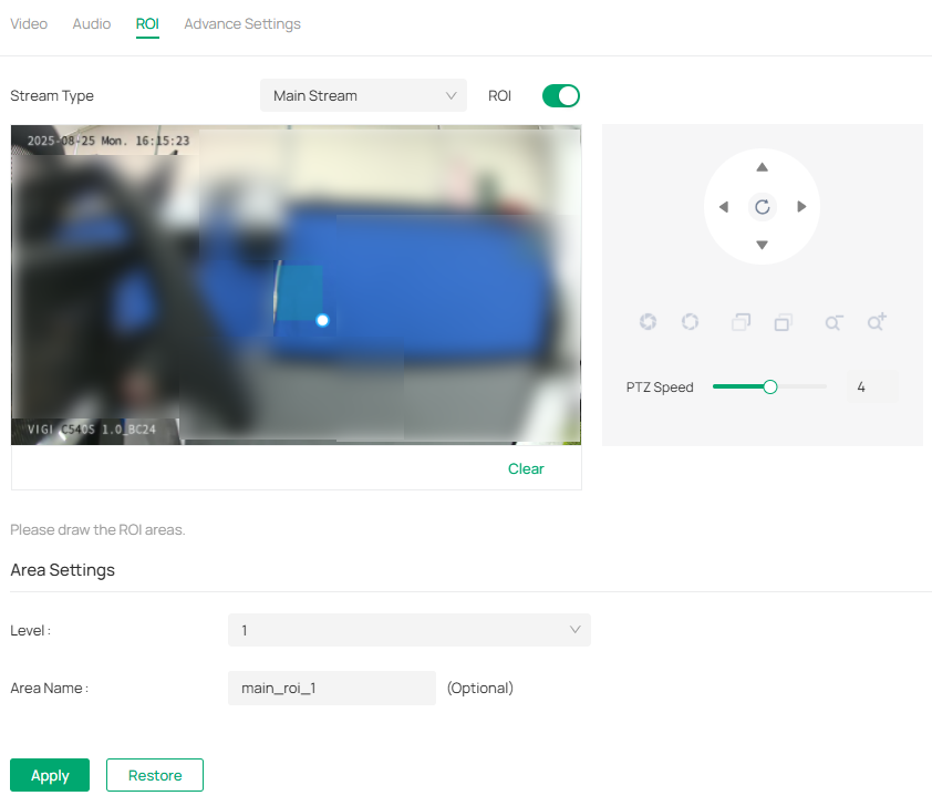
9. 3. 4 Advanced Settings
In Advanced Settings, you can set QoS and SRTP.
QoS (Quality of Service) can help improve the network delay and network congestion by setting the priority of data sending.
SRTP (Secure Real-time Transport Protocol) is a Real-time Transport Protocol (RTP) Internet protocol, intended to provide encryption, message authentication and integrity, and replay attack protection to the RTP data in both uni-cast and multi-cast applications.
1. Go to Devices. Select the site where your device is located, find the device in the list, and click .
2. In the panel on the right, go to Camera > Stream > Advanced Settings.
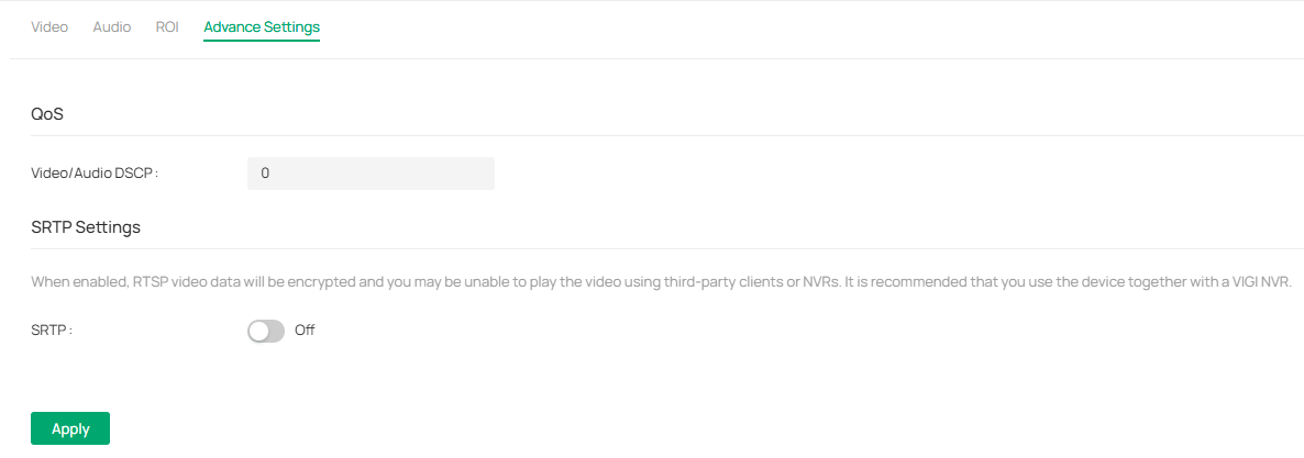
3. Set Video/Audio DSCP.
Network can identify the priority of data transmission. The bigger the DSCP value is, the higher the priority is.
4. Enable SRTP if needed. When enabled, RTSP video data will be encrypted and you may be unable to play the video using third-party clients or NVRs. It is recommended that you use the device together with a VIGI NVR.
5. Click Apply.
9. 4 PTZ (Only for Models with Motorized Lens)
VIGI VMS provides PTZ control operations via control panel, such as zoom in, zoom out, and auxiliary focus. You can also open a new window for controlling the PTZ.
1. Go to Devices. Select the site where your device is located, find the device in the list, and click  .
.
2. In the panel on the right, go to PTZ and configure the following parameters.
|
|
Zoom Out |
(Only for certain cameras) Click to zoom out the live image. |
|
|
Zoom In |
(Only for certain cameras) Click to zoom in the live image. |
|
|
Focus - |
(Only for certain cameras) Shorten the focal length. |
|
|
Focus + |
(Only for certain cameras) Increase the focal length. |
|
|
Lens Initialization |
(Only for the camera with motorized lens) Click to reset lens when long time zoom or focus results in blurred image. |
|
|
Auxiliary Focus |
(Only for the camera with motorized lens) Click to focus automatically. |
|
|
PTZ Speed |
Adjust the speed of the PTZ camera’s movement by sliding the bar to the left (slower) or to the right (faster). The speed is set at 4 by default, but it can be adjusted depending on how fast you want the camera to move. |
|
|
3D Positioning |
The 3D Positioning button enables or disables the 3D view for the camera. When active, this feature provides a 3D representation of the camera’s field of view, which can help you better visualize its surroundings and plan the camera’s movement and positioning. |
|
|
Quick Patrol |
The Quick Patrol option enables the camera to quickly cycle through predefined preset positions. When activated, the camera will automatically move between preset locations on the map or field of view, offering a quick and automated patrol of the area. You can set up different patrols by configuring the presets. |
|
|
Quick Park |
Quick Park is used to quickly park the camera back to a default or home position after it has been adjusted. It returns the camera to a preset position, ensuring it is safely positioned after completing a task. |


9. 4. 1 Preset
The Preset feature allows you to store specific camera positions and quickly move the camera to those positions with a single click. This is ideal for focusing on particular areas or monitoring multiple zones within a scene. You can configure multiple presets based on your surveillance needs and easily switch between them.

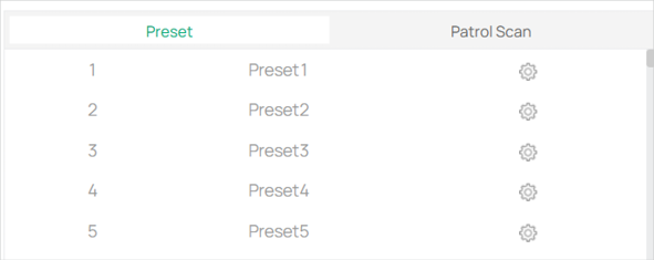
1. Select preset position. On the Preset list, choose a preset number (e.g., Preset1, Preset2, etc.). These presets represent predefined camera positions that are saved in the system.
2. Adjust the camera to preset position. Click on a preset to instantly move the camera to the corresponding position. This is useful for quick views of specific areas.
3. Modify or create a new preset. To adjust a preset, click the gear icon next to the preset number. This opens a settings menu where you can configure the camera’s position and save it to a preset. You can create or update up to the maximum number of presets allowed by the camera.
4. Switch between presets. Simply click on the desired preset number to move the camera to the stored position.
9. 4. 2 Patrol Scan
The Patrol Scan feature enables the camera to automatically cycle through multiple preset positions in a set order, creating a patrol path. This allows for continuous automated surveillance, making it perfect for monitoring large areas without manual intervention. You can configure the camera to scan specific locations at a desired interval, providing efficient coverage.

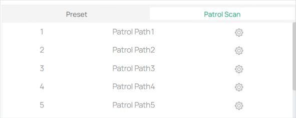
1. In the Preset section, select a Preset number (e.g., Preset 1) and click the gear icon next to it.
2. You can create a new preset by selecting the + button.

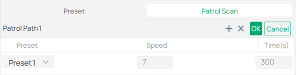
3. To move the camera to a predefined position, simply click on the Preset number (e.g., Preset1, Preset2).
4. Specify the speed and times for repetition.
5. Click OK when it’s done.
9. 4. 3 Park
The Park feature allows the camera to automatically return to a preset position after a defined amount of time. This is ideal for setting the camera to a “rest” position when not actively monitoring or tracking. The camera will move to a preset location after a specific period, ensuring it remains in a known, static position, reducing unnecessary movement or wear.
1. Go to Devices. Select the site where your device is located, find the device in the list, and click ![]() .
.
2. In the panel on the right, go to PTZ > Park.

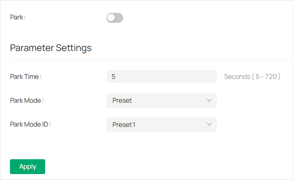
3. Toggle on Park to enable the feature.
4. In the Park Time field, input the time (in seconds) after which the camera will park itself at the selected preset. The available range is from 5 to 720 seconds.
5. From the Park Mode drop-down menu, select the mode in which the camera will park. The default mode is Preset, which ensures the camera parks at a predefined position.
6. Choose the preset position where the camera will park from the Park Mode ID drop-down (e.g., Preset1).
7. Click Apply to save the settings and activate the park feature.
9. 4. 4 Target Track
The Target Track feature allows the camera to automatically track a moving object within its field of view. This feature is helpful when monitoring dynamic scenes, as the camera will follow the target without manual intervention. However, this feature won’t work when the camera is in patrol mode and may interfere with other detection functions.
1. Go to Devices. Select the site where your device is located, find the device in the list, and click ![]() .
.
2. In the panel on the right, go to PTZ > Target Track.

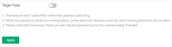
3. Toggle on the Target Track option to activate the tracking functionality.
Note:
• The Target Track feature will not function when the camera is in patrol mode.
• The camera may not track properly when monitoring a moving object if certain detection features (such as Line Crossing Detection) are active.
• Be aware that privacy masks set in the camera settings might be exposed due to scene changes caused by tracking.
• After enabling the feature, click Apply to save and activate the target tracking.
9. 5 Event
This feature enables you to configure the event settings and alarm actions when your cameras detect different types of events. VIGI camera monitors your pre-defined areas and you’ll be automatically alerted to any suspicious activity in your home and office:
9. 5. 1 Arming Schedule and Processing Mode
Arming schedule is a customized time period in which the device performs certain tasks. Linkage is the response to the detected certain incident or target during the scheduled time. This configuration is optional.
1. Go to Devices. Select the site where your device is located, find the device in the list, and click ![]() .
.
2. In the panel on the right, go to Event and locate Arming Schedule and Processing Mode in the related event interface.

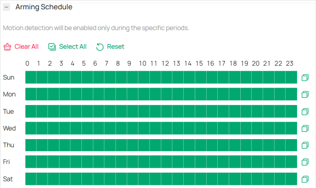
3. Drag the time bar to draw desired valid time.
Note:
• Each cell represents one hour.
• The default setting is 24/7.
• Up to six time periods can be configured for a day.
4. Double click the time block you have drawn and a pop up window will appear. Fine-tune the start time and end time (with an accuracy of a minute) and click Confirm. You may copy a schedule for a day to any other days.

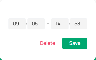
5. Set linkage methods as needed.
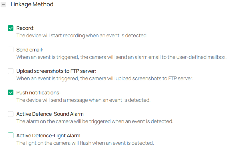
9. 5. 2 Message
1. Go to Devices. Select the site where your device is located, find the device in the list, and click ![]() .
.
2. In the panel on the right, go to Event > Message and configure the following parameters.

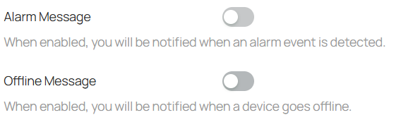
9. 5. 3 Motion Detection
Motion detection allows cameras to detect the moving objects in the monitored area and triggers alarm actions. You can customize the motion detection settings, set the alarm schedule, and select the triggered actions. Follow the steps below to finish the configuration.
1. Go to Devices. Select the site where your device is located, find the device in the list, and click ![]() .
.
2. In the panel on the left, go to Event > Basic Event > Motion Detection.

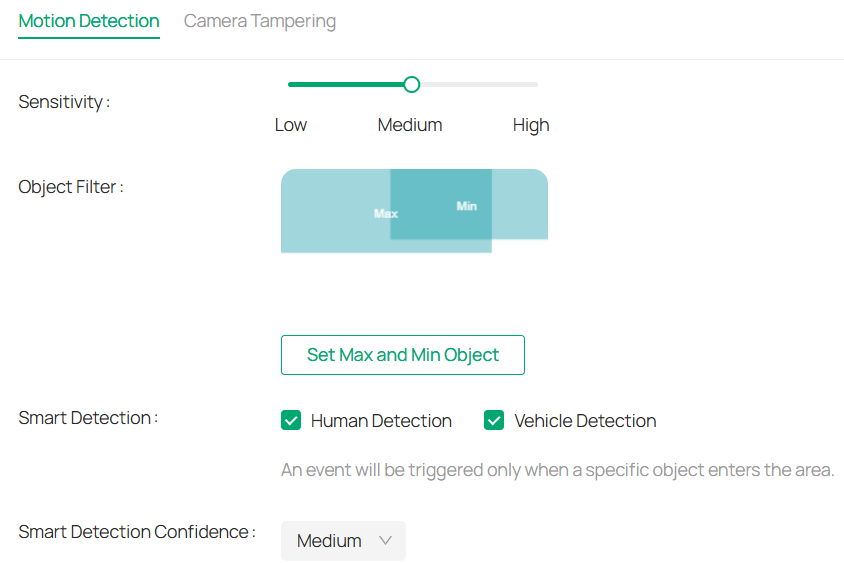
3. Draw quadrilaterals for motion detection on the preview screen.
The whole screen is selected by default. You may drag the corners to change the shape of the area and drag the whole area to move it. You may delete a selected area and clear all areas.
Note: You may customize up to four areas.
4. Modify the following parameters:

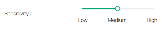
|
Sensitivity |
Adjust the value of sensitivity. The higher the value is, the easier it is to trigger an alarm. |
|---|---|
|
Object Filter |
Click Set Max and Min Object, then draw boxes to define the smallest and largest object sizes you want to detect. Motion outside this range won’t trigger events. |
|
Smart Detection |
Choose whether you want to detect humans only, vehicles only, or both. The function is available only for cameras which support human detection and vehicle detection. |
|
Smart Detection Confidence |
Select the detection type from High, Medium, and Low. The function is available only for the cameras which support human detection and vehicle detection. |
5. Refer to Arming Schedule and Processing Mode for settings if needed.
6. Click Apply.
9. 5. 4 Camera Tempering
Camera tampering triggers alarm actions when an area of camera’s lens is purposely blocked, obstructed or vandalized. You can customize the video tampering settings, select the triggered actions and set the alarm schedule for cameras. Follow the steps below to finish the configuration.
1. Go to Devices. Select the site where your device is located, find the device in the list, and click ![]() .
.
2. In the panel on the left, go to Event > Basic Event > Camera Tempering.

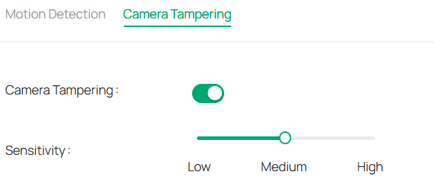
3. Enable Camera Tampering.
4. Set the sensitivity of video tampering. A higher value can trigger the alarm actions more easily.
5. Refer to Arming Schedule and Processing Mode for settings if needed.
6. Click Apply.
9. 5. 5 Human Detection
Human detection triggers alarm actions when cameras detect persons are moving in the specified areas. You can customize the area settings, select the triggered actions and set the alarm schedule. Follow the steps below to finish the configuration.
1. Go to Devices. Select the site where your device is located, find the device in the list, and click ![]() .
.
2. In the panel on the left, go to Event > Smart Event > Human Detection. Click the toggle to turn it on.

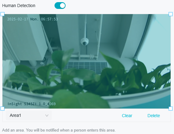
3. Adjust the value of sensitivity. A higher value can trigger alarm actions more easily.
4. Refer to Arming Schedule and Processing Mode for settings if needed.
5. Click Apply.
9. 5. 6 Vehicle Detection
Vehicle detection triggers alarm actions when cameras detect cars are moving in the specified areas. You can customize the area settings, select the triggered actions and set the alarm schedule. Follow the steps below to finish the configuration.
1. Go to Devices. Select the site where your device is located, find the device in the list, and click ![]() .
.
2. In the panel on the left, go to Event > Smart Event > Abnormal Sound Detection. Click the toggle to turn it on.

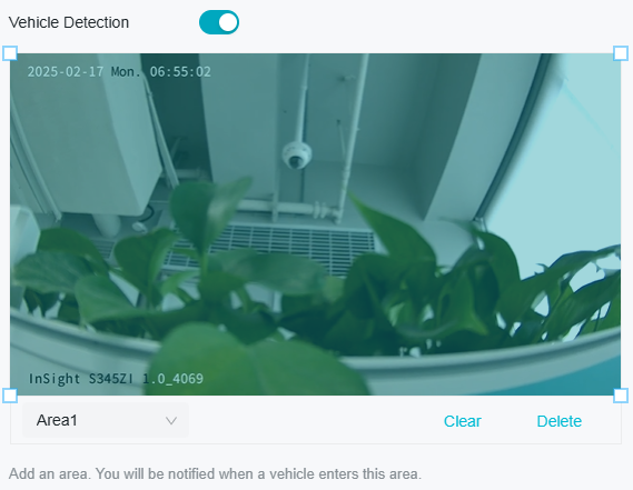
3. Adjust the value of sensitivity. A higher value can trigger alarm actions more easily.
4. Refer to Arming Schedule and Processing Mode for settings if needed.
5. Click Apply.
9. 5. 7 Line Crossing Detection
Line crossing detection triggers alarm actions when cameras detect that moving objects cross a customized virtual line. Follow the steps below to finish the configuration.
1. Go to Devices. Select the site where your device is located, find the device in the list, and click ![]() .
.
2. In the panel on the right, go to Event > Smart Event > Line Crossing Detection. Click the toggle to turn it on.

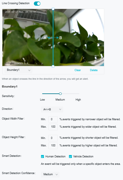
3. Draw lines on the preview screen. Select the line and configure its settings.
Note: You can draw up to four lines and need to configure settings for each line.
|
Sensitivity |
The higher the value is, the easier it is to detect a target that crosses the line. |
|---|---|
|
Direction |
Choose the direction from which the target crosses the line. A->B: Only the target crossing the configured line from the A side to the B side can be detected. B->A: Only the target crossing the configured line from the B side to the A side can be detected. A<->B: The target going across the line from both sides can be detected and alarms are triggered. |
|
Object Filter |
Click Set Max and Min Object, then draw boxes to define the smallest and largest object sizes you want to detect. Motion outside this range won’t trigger events. |
|
Smart Detection |
Choose whether you want to detect humans only, vehicles only, or both. The function is available only for cameras which support human detection and vehicle detection. |
|
Smart Detection Confidence |
Select the detection type from High, Medium, and Low. The function is available only for the cameras which support human detection and vehicle detection. |
4. Refer to Arming Schedule and Processing Mode for settings if needed.
5. Click Apply.
9. 5. 8 Intrusion Detection
Intrusion detection is used to detect objects entering and loitering in a predefined virtual region. Once it happens, the camera will take linkage actions. Follow the steps below to finish the configuration.
1. Go to Devices. Select the site where your device is located, find the device in the list, and click ![]() .
.
2. In the panel on the left, go to Event > Smart Event > Intrusion Detection. Click the toggle to turn it on.

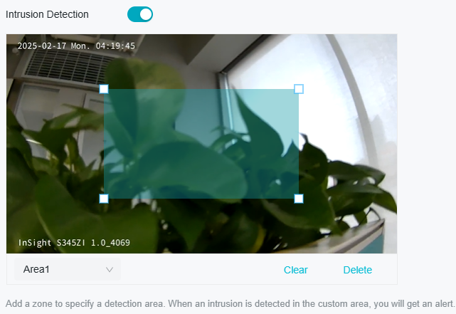
3. Draw intrusion areas on the preview screen. Select the area and configure the settings.
Note: You may draw up to four areas and need to configure settings for each area.
|
Sensitivity |
The higher the value is, the more easily an intrusion action can be detected. |
|---|---|
|
Percentage |
Set the percentage of intrusion detection. When an object takes up the specific percentage of the area, the alarm actions will be triggered. |
|
Intrusion Time |
Intrusion time stands for the threshold a target loiters in the area. Any stay longer than the intrusion time will trigger the linkage action. |
|
Object Filter |
Click Set Max and Min Object, then draw boxes to define the smallest and largest object sizes you want to detect. Motion outside this range won’t trigger events. |
|
Smart Detection |
Choose whether you want to detect humans only, vehicles only, or both. The function is available only for cameras which support human detection and vehicle detection. |
|
Smart Detection Confidence |
Select the detection type from High, Medium, and Low. The function is available only for the cameras which support human detection and vehicle detection. |
4. Refer to Arming Schedule and Processing Mode for settings if needed.
5. Click Apply.
9. 5. 9 Region Entering Detection
Region entering detection triggers alarm actions when cameras detect moving objects enter the specified regions. You can customize the region settings, select the triggered actions and set the alarm schedule. Follow the steps below to finish the configuration.
1. Go to Devices. Select the site where your device is located, find the device in the list, and click ![]() .
.
2. In the panel on the left, go to Event > Smart Event > Region Entering Detection. Click the toggle to turn it on.

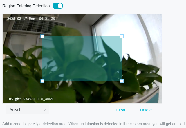
3. Draw shapes for area entrance detection on the preview screen.
Note: You may draw up to four areas and need to configure settings for each area.
|
Sensitivity |
Adjust the value of sensitivity. A higher value can trigger alarm actions more easily. |
|---|---|
|
Object Filter |
Click Set Max and Min Object, then draw boxes to define the smallest and largest object sizes you want to detect. Motion outside this range won’t trigger events. |
|
Smart Detection |
Choose whether you want to detect humans only, vehicles only, or both. The function is available only for cameras which support human detection and vehicle detection. |
|
Smart Detection Confidence |
Select the detection type from High, Medium, and Low. The function is available only for the cameras which support human detection and vehicle detection. |
4. Refer to Arming Schedule and Processing Mode for settings if needed.
5. Click Apply.
9. 5. 10 Region Exiting Detection
Region exiting detection triggers alarm actions when cameras detect moving objects exit the specified regions. You can customize the region settings, select the triggered actions and set the alarm schedule. Follow the steps below to finish the configuration.
1. Go to Devices. Select the site where your device is located, find the device in the list, and click ![]() .
.
2. In the panel on the left, go to Event > Smart Event > Region Exiting Detection. Click the toggle to turn it on.

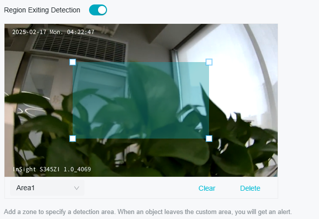
3. Draw shapes for area exiting detection on the preview screen.
Note: You may draw up to four areas and need to configure settings for each area.
|
Sensitivity |
Adjust the value of sensitivity. A higher value can trigger alarm actions more easily. |
|---|---|
|
Object Filter |
Click Set Max and Min Object, then draw boxes to define the smallest and largest object sizes you want to detect. Motion outside this range won’t trigger events. |
|
Smart Detection |
Choose whether you want to detect humans only, vehicles only, or both. The function is available only for cameras which support human detection and vehicle detection. |
|
Smart Detection Confidence |
Select the detection type from High, Medium, and Low. The function is available only for the cameras which support human detection and vehicle detection. |
4. Refer to Arming Schedule and Processing Mode for settings if needed.
5. Click Apply.
9. 5. 11 Loitering Detection
Loitering detection triggers alarm actions when a moving object remains in a predefined area for a specific amount of time. You can customize the area settings, select the triggered actions and set the alarm schedule. Follow the steps below to finish the configuration.
1. Go to Devices. Select the site where your device is located, find the device in the list, and click ![]() .
.
2. In the panel on the left, go to Event > Smart Event > Loitering Detection. Click the toggle to turn it on.

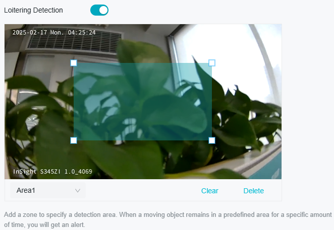
3. Draw shapes for area exiting detection on the preview screen.
Note: You may draw up to four areas and need to configure settings for each area.
|
Sensitivity |
Adjust the value of sensitivity. A higher value can trigger alarm actions more easily. |
|---|---|
|
Loitering Time |
It stands for the threshold for the time of the object loitering in the region. If the time that one object stays exceeds the threshold, the alarm is triggered. |
|
Object Filter |
Click Set Max and Min Object, then draw boxes to define the smallest and largest object sizes you want to detect. Motion outside this range won’t trigger events. |
|
Smart Detection |
Choose whether you want to detect humans only, vehicles only, or both. The function is available only for cameras which support human detection and vehicle detection. |
|
Smart Detection Confidence |
Select the detection type from High, Medium, and Low. The function is available only for the cameras which support human detection and vehicle detection. |
4. Refer to Arming Schedule and Processing Mode for settings if needed.
5. Click Apply.
9. 5. 12 Object Abandoned/Removal Detection
Object abandoned/removal detection triggers alarm actions when cameras detect objects are left behind or taken away in the specified areas. You can customize the area settings, select the triggered actions and set the alarm schedule. Follow the steps below to finish the configuration.
1. Go to Devices. Select the site where your device is located, find the device in the list, and click ![]() .
.
2. In the panel on the left, go to Event > Smart Event > Object Abandoned/Removal Detection. Click the toggle to turn it on.
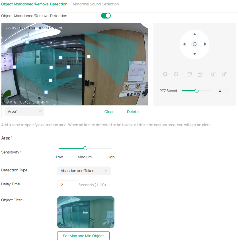
3. Draw shapes for area exiting detection on the preview screen.
Note: You may draw up to four areas and need to configure settings for each area.
|
Sensitivity |
Adjust the value of sensitivity. A higher value can trigger alarm actions more easily. |
|---|---|
|
Detection Type |
Select the detection type. Abandon: Detects when a new object (e.g. a bag, box, or parcel) is left in the scene and stays there for a set period. Taken: Detects when an existing object is removed from its original position. Abandon and Taken: Detects both when a new object is left behind and when an existing object is removed. |
|
Delay Time |
Set how long the object is left behind or taken away to trigger the event. |
|
Object Filter |
Click Set Max and Min Object, then draw boxes to define the smallest and largest object sizes you want to detect. Motion outside this range won’t trigger events. |
4. Refer to Arming Schedule and Processing Mode for settings if needed.
5. Click Apply.
9. 5. 13 Scene Change Detection
Scene change detection function detects the change of video security environment affected by the external factors, such as intentional rotation of the camera. Certain actions can be taken when the alarm is triggered. Follow the steps below to finish the configuration.
1. Go to Devices. Select the site where your device is located, find the device in the list, and click ![]() .
.
2. In the panel on the left, go to Event > Basic Event > Scene Change.
3. Click the toggle to turn on Scene Change.

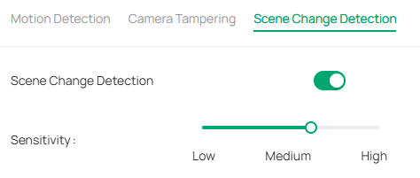
4. Specify Sensitivity. The higher the value is, the more easily the change of the scene can be detected.
5. Refer to Arming Schedule and Processing Mode for settings if needed.
6. Click Apply.
9. 5. 14 Abnormal Sound Detection
Abnormal sound detection identifies uncommon or irregular sounds and triggers alarm actions. You can select the triggered actions and set the alarm schedule. Follow the steps below to finish the configuration.
1. Go to Devices. Select the site where your device is located, find the device in the list, and click ![]() .
.
2. In the panel on the left, go to Event > Smart Event > Abnormal Sound Detection. Click the toggle to turn it on.

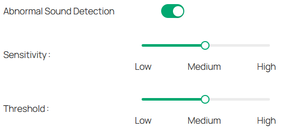
3. Adjust the value of sensitivity and alert threshold. The higher the sensitivity and the lower the threshold, the easier it gets to trigger processing methods.
4. Refer to Arming Schedule and Processing Mode for settings if needed.
5. Click Apply.
9. 5. 15 Access Exception
Set the maximum login attempts to protect the security of your camera. The camera will be locked for 30 minutes if you enter the wrong password more than the specified attempts. Follow the steps below to finish the configuration.
1. Go to Devices. Select the site where your device is located, find the device in the list, and click ![]() .
.
2. In the panel on the left, go to Event > Exception Event > Access Exception. Click the toggle to turn it on.

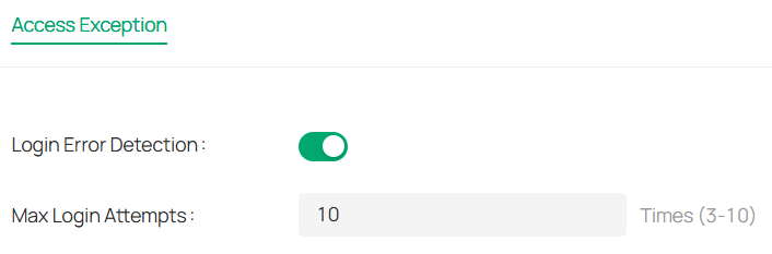
3. Enable Login Error Detection to limit the login attempts:
4. Set the maximum login attempts. The number should between 3 and 10
5. Click Apply.
Note: To unlock the camera and try to log in again, power the camera off and then power it on.
9. 5. 16 Light Alarm
The Light Alarm enhances deterrence by triggering a visual alert upon intrusion detection.
1. Go to Devices. Select the site where your device is located, find the device in the list, and click ![]() .
.
2. In the panel on the left, go to Event > Active Defence > Light Alarm. Toggle Arm Status to On (green) to activate the defense system.

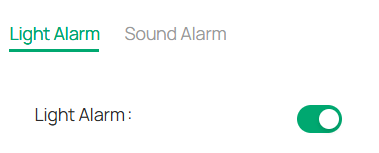
3. Select the Light Alarm tab. Toggle the Light Alarm switch to On.
4. Configure the following:
|
Duration |
Choose the desired light duration: Default: Uses the system-defined activation period. Custom: Enables user-defined timing (requires additional input). |
|---|---|
|
Flicker Frequency |
Select the desired Flicker Frequency, including Low, Medium, and High, from the dropdown menu. Higher frequency is recommended for higher-risk areas. |
|
Brightness |
Adjust the Brightness using the slider or by directly entering a value (range: 0–100). |
5. Refer to Arming Schedule and Processing Mode for settings if needed.
6. Click Apply.
9. 5. 17 Sound Alarm
Enable Sound Alarm, then the alarm on the camera will be triggered when an event is detected.
1. Go to Devices. Select the site where your device is located, find the device in the list, and click ![]() .
.
2. In the panel on the right, go to Event > Active Defence > Sound Alarm. Click the toggle to turn it on. Select the Alarm Type, and click Test.

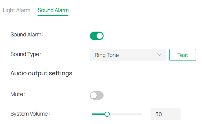
3. Under Audio Output Settings, click the toggle to mute or drag the slide bar to set the system volume.
4. Refer to Arming Schedule and Processing Mode for settings if needed.
5. Click Apply.
9. 5. 18 Alarm Server
The device can send alarms to destination IP address or host name through HTTP, HTTPS, or ISUP protocol. The destination IP address or host name should support HTTP, HTTP, or ISUP data transmission.
1. Go to Devices. Select the site where your device is located, find the device in the list, and click ![]() .
.
2. In the panel on the left, go to Event > Alarm Server.
3. Click Add.

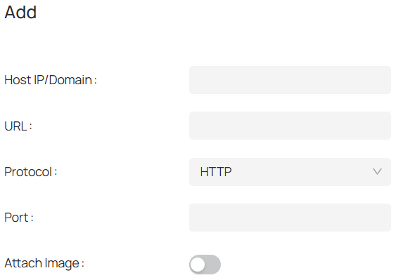
4. Enter Host IP/Domain, URL, and Port, and select Protocol. Enable Attach Image if needed.
Note: HTTP and HTTPS are selectable. It is recommended to use HTTPS, as it encrypts the data transmission during communication.
5. Click Save.
9. 6 Smart
The Smart feature adds intelligence to video surveillance by automatically detecting and analyzing events, objects, and behaviors in the scene. It helps improve security, streamline searches, and reduce false alarms by focusing attention on what matters most.
9. 6. 1 Smart Analysis Configuration
Use Smart Analysis Configuration to enhance video analytics.
1. Go to Devices. Select the site where your device is located, find the device in the list, and click ![]()
 .
.
2. In the panel on the left, go to Event > Smart > Smart Analysis Configuration.

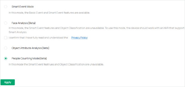
3. Enable one of the modes below.
|
Smart Event Mode |
Enable this mode to activate intelligent detection features, such as motion, intrusion, and object-related events. |
|---|---|
|
Face Analysis (Beta) |
In this mode, the Smart Event features and Object Classification are unavailable. To use this mode, the device should work with an NVR that support Smart Analysis. |
|
Object Attribute Analysis (Beta) |
Turn on this feature to analyze detailed attributes of people and vehicles captured in the scene. This feature is in beta and may vary depending on your camera model. |
|
People Counting Mode (Beta) |
In this mode, the Smart Event featrues and Object Classification are unavailable. |
9. 6. 2 Face Analysis
To use Face Analysis, you need to first enable it.
1. Go to Devices. Select the site where your device is located, find the device in the list, and click ![]() .
.
2. In the panel on the left, go to Event > Smart > Smart Analysis Configuration.
3. Enable Face Analysis (Beta).
To refine your configuration, go to Event > Smart > Face Analysis.
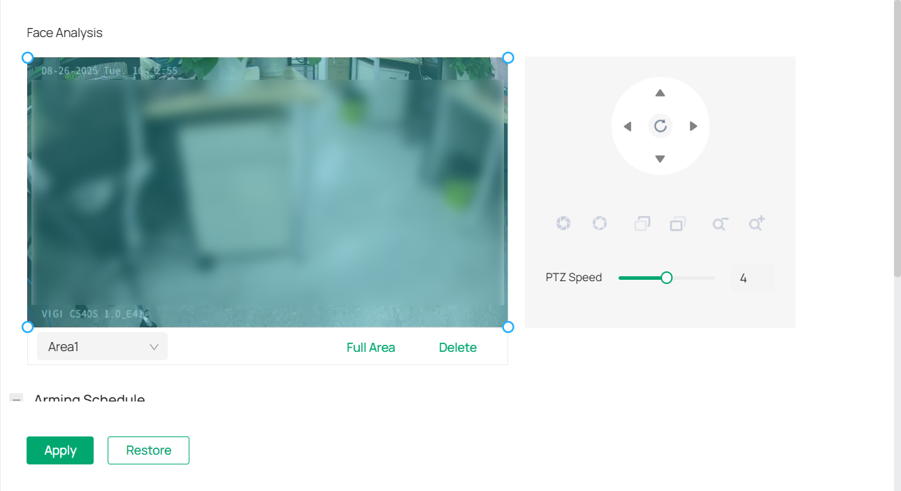
1. Draw the area for facial recognition.
2. Refer to Arming Schedule and Processing Mode for settings if needed.
3. Click Apply.
9. 6. 3 Object Attribute Analysis
When Object Attribute Analysis (Beta) is enabled, you can further refine your analytics:
1. Go to Devices. Select the site where your device is located, find the device in the list, and click ![]() .
.
2. In the panel on the left, go to Event > Smart > Object Attribute Analysis.

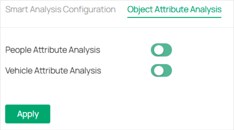
3. You can enable either People Attribute Analysis, Vehicle Attribute Analysis, or both, depending on your surveillance needs.
|
People Attribute Analysis |
Detects and analyzes attributes like clothing color, gender, accessories, or other human characteristics (depending on camera capabilities). Useful for searching or filtering events involving specific people. |
|---|---|
|
Vehicle Attribute Analysis |
Detects and analyzes vehicle details such as type (car, truck, bike), color, or presence of license plates (depending on camera capabilities). Helps in investigations or monitoring specific vehicle activity. |
9. 6. 4 People Counting
To use People Counting, you need to first enable it.
1. Go to Devices. Select the site where your device is located, find the device in the list, and click ![]() .
.
2. In the panel on the left, go to Event > Smart > Smart Analysis Configuration.
3. Enable People Counting (Beta).
To refine your configuration, go to Event > Smart > People Counting.
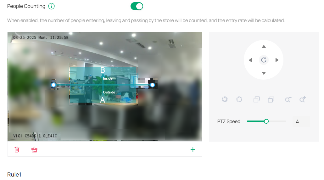
1. Draw the area for counting the number of people.
2. Refer to Arming Schedule and Processing Mode for settings if needed.
Note:
• It is recommended to use People Counting in scenes with stable and sufficient lighting. If used indoors, ensure that there is sufficient ambient light.
• Keep the detection area clear and unobstructed.
• Recommended installation height of camera installation height is less than 5 meters.
• Keep the camera’s top-down angle between 20° and 60° to ensure that the target’s entire head appears within the detection area.
• People counting recognizes people by detecting their head features. The minimum head height in the recognition area must be greater than 5% of the video screen height.
9. 7 Storage
9. 7. 1 Recording Schedule
Recording schedule section provides convenience and flexibility for the daily monitoring of your camera. You can customize the recording schedules. You can set different schedules for each day. In Advanced Settings page, you can set the pre-recording time and delay time for recording.
1. Go to Devices. Select the site where your device is located, find the device in the list, and click ![]()
 .
.
2. In the panel on the right, go to Storage > Recording Schedule.
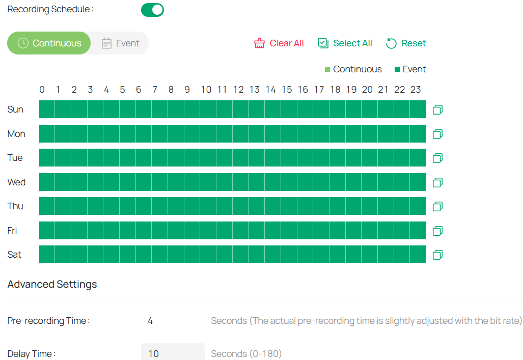
3. Enable Recording Schedule, select Continuous Recording or Motion Detection, then select the time period.
|
Continuous Recording |
The camera will record continuously. |
|---|---|
|
Event Recording |
The camera will record when a movement is detected. |
|
Pre-recording Time |
The time is set for cameras to record before the scheduled time or event. For example, the schedule for continuous recording starts at 10:00. If you set the pre-recording time as 5 seconds, the camera starts to record at 9:59:55. |
|
Delay Time |
The time is set for cameras to record after the scheduled time or event. For example, if you set the post-record time as 5 seconds, it records till 11:00:05 as motion detection ends at 11:00. |
4. Double click the time block you have drawn and a pop up window will appear. Fine-tune the start time and end time (with an accuracy of a minute) and click Confirm. You may copy a schedule for a day to any other days.

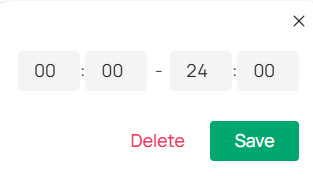
5. Click Apply.
9. 7. 2 Storage Management
In Storage Management, you can view the parameters and configure the properties and disk group of SD card. You can also enable the camera to overwrite the earlier recording files when the SD card is full.
1. Go to Devices. Select the site where your device is located, find the device in the list, and click ![]() .
.
2. In the panel on the right, go to Storage > Storage Management.
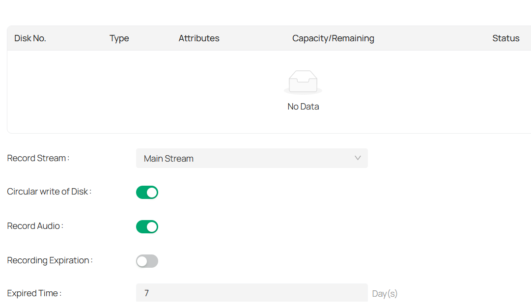
3. Click Format to initialize the memory card.
When the Status of memory card turns from Uninitialized to Normal, the memory card is ready for use.
4. Specify advanced settings.
|
Record Streams |
Select the stream type for recording. Main Stream stands for the best stream performance the device supports. It usually offers the best resolution and frame rate the device can do. But high resolution and frame rate usually means larger storage space and higher bandwidth requirements in transmission. Sub-stream usually offers comparatively low resolution options, which consumes less bandwidth |
|---|---|
|
Circular Write of Disk |
Enable Circular Write of Disk to overwrite the video records when the storage space is full. Otherwise the camera cannot record new videos. |
|
Record Audio |
Enable to record audio and video simultaneously. |
|
Recording Expiration |
Enable Recording Expiration to delete recordings when they exceed the expired time. Note that once the recordings are deleted, they cannot be recovered. |
|
Expired Time |
Set the time when recordings will be automatically deleted. |
5. Click Apply.
9. 8 Network
With proper network configurations, you can connect your camera to the Internet, build up mapping between internal and external ports.
9. 8. 1 Internet Connection
In Internet Connection, you can view the connection status and configure the camera to obtain a dynamic or static IP address.
Follow the steps below to configure the network settings.
1. Go to Devices. Select the site where your device is located, find the device in the list, and click ![]()
 .
.
2. In the panel on the right, go to Network > Internet Connection.

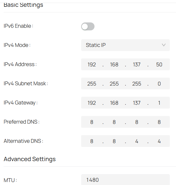
|
Status |
Displays the current Internet status. |
|---|---|
|
IPv6 Enable |
Enable to configure IPv6 settings. IPv4 and IPv6 are both supported. Both versions can be configured simultaneously without conflicting to each other. Router Advertisement: The IPv6 address is generated by combining the route advertisement and the device Mac address. Note that this mode requires the support from the router that the device is connected to. DHCP: The IPv6 address is assigned by the server, router, or gateway. Manual: Input IPv6 Address, IPv6 Subnet Mask, and IPv6 Gateway. Consult the network administrator for required information. |
|
IPv4 Mode |
Configure the camera to obtain a dynamic or static IP address. |
|
IPv4 Address |
Specify an IP address for the camera. The IP address should be in the same segment as the gateway; otherwise, the camera cannot connect to the Internet. |
|
IPv4 Subnet Mask |
Enter the subnet mask. |
|
IPv4 Gateway |
Enter the IP address of the gateway device to which the data packets will be sent. This IP address should be in the same segment as the camera’s IP address. |
|
Preferred /Alternative DNS |
Enter the IP address of the DNS server. |
|
MTU |
Specify MTU (Maximum Transmission Unit) to decide the largest size of data unit that can be transmitted in the network. A larger unit can improve the efficiency with more data in each packet, but it may increase the network delay because it needs more time to transmit. Therefore, if you have no special needs, it is recommended to keep the default value. |
|
Adaptive IP |
Enable this option if you want to set the camera’s IP to change according to the network topology. |
Note: The cameras should be in the same segment with the NVR, so that the NVR can discover and manage them.
3. Click Apply.
9. 8. 2 Port
In Port, you can configure the HTTPS port and service port of devices that can be used to access the camera through the network. When managing and monitoring the devices via the VMS, the ports configured here are used for communications of corresponding protocols.
1. Go to Devices. Select the site where your device is located, find the device in the list, and click ![]() .
.
2. In the panel on the right, go to Network > Port.

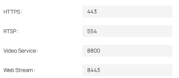
3. Specify HTTPS port and service port.
|
HTTPS |
Specify a port for HTTPS protocol. |
|---|---|
|
RTSP |
Specify a port for RTSP (Real Time Streaming Protocol) protocol. RTSP is an application layer protocol for connecting, transferring, and streaming media data in real time from IP cameras connected to the network. rtsp://username:password@ip:port/streamNo ip – IP of the Camera. port – Default port is 554. This can be skipped. streamNo – Stream number. Stream1 refers to the main stream; stream2 refers to the substream. Example URL: rtsp://admin:123456@192.168.1.60:554/stream1 This will display the main stream of the camera, where admin is the user name and 12345 is the password. |
|
Video Service |
Specify a port for protocols of video services. |
|
Web Stream |
Specify a port to access the camera’s live streaming web interface. |
4. Click Save.
9. 8. 3 Email
When the email is configured and enabled as a linkage method, the device sends an email notification to all designated recipients if an alarm event is detected.
1. Go to Devices. Select the site where your device is located, find the device in the list, and click ![]() .
.
2. In the panel on the right, go to Network > Email.

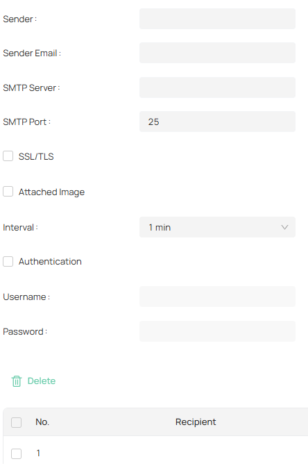
3. Input the sender’s email information, including the Sender’s name, Sender Email, SMTP Server, and SMTP Port. It is recommended to configure the SMTP port number to the default value of 25.
4. Enable SSL/TLS if needed and emails will be sent after encrypted.
5. Check Attached Image to receive notification with alarm pictures.
The notification email has a certain number of attached alarm pictures about the event with configurable image capturing interval.
6. If your email server requires authentication, check Authentication and input your username and password to log in to the server.
7. Click Edit to Input the recipient’s information, including the recipient’s name and address.
8. Click Test to see if the function is well configured.
9. Click Apply.
9. 8. 4 Port Forwarding
Port Forwarding is used to establish the mapping between the internal port and external port. When Port Forwarding is enabled, you can access the device and watch the videos when accessing the external port remotely.
Note: The cameras should be connected to the Internet, and Port Forwarding should be enabled on the gateway.
Follow the steps below to configure Port Forwarding.
1. Go to Devices. Select the site where your device is located, find the device in the list, and click ![]() .
.
2. In the panel on the right, go to Network > Port Forwarding.
3. Enable Port Forwarding and specify a mapping type. If you select Auto as the mapping type, the mappings are established automatically. If you select Manual as the mapping type, click ![]()
![]() to specify the external port.
to specify the external port.
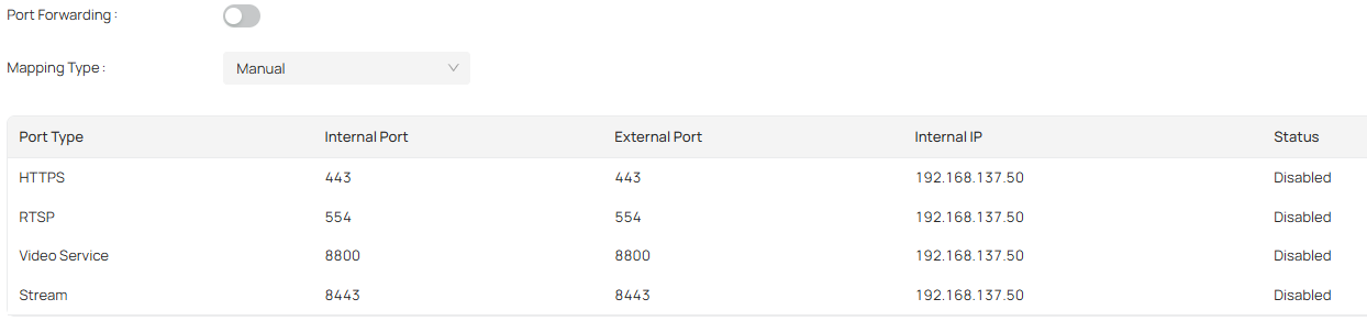
|
Port Type |
Displays the protocol type. |
|---|---|
|
Internal Port |
Displays the port of the camera to be converted. |
|
External Port |
Displays the external port opened by the gateway. |
|
Internal IP |
Displays the IP address of the camera that needs to be converted. |
|
Status |
Displays the status of mapping. |
|
Restore |
Click to restore the settings to default factory settings. |
4. Click Save.
With Port Forwarding enabled, you can remotely watch the videos with the URL rtsp://A.B.C.D:Port/streamN, for example, rtsp://10.0.1.47:28736/stream1. A.B.C.D is the WAN IP address of the gateway, and Port is the number of RTSP external port. N can be number 1 or 2 that indicates the stream, 1 for main stream and 2 for sub-stream.
9. 8. 5 IP Restriction
When IP Restriction is enabled, you can add IP addresses to the deny list or allow list to restrict the access to the camera. The IP address in the deny list cannot access the camera, while only the IP addresses in the allow list can access the camera.
Follow the steps below to configure IP Restriction.
1. Go to Devices. Select the site where your device is located, find the device in the list, and click ![]() .
.
2. In the panel on the right, go to Network > IP Restriction.
3. Enable IP Restriction and specify the restriction rule. If you select Deny List, the devices with the IP addresses specified in the table will not be able to access the camera. If you select Allow List, only the devices with the IP addresses specified in the table can access the camera.

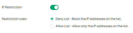
4. Click Add to add the desired IP address, give a description to identify this IP address, then click Save.

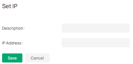
5. Click Save.
9. 8. 6 Multicast
When Multicast is enabled, you can watch videos using the multicast address and port.
Follow the steps below to configure Multicast.
1. Go to Devices. Select the site where your device is located, find the device in the list, and click ![]() .
.
2. In the panel on the right, go to Network > IP Restriction.
3. Select the stream type, then enable Multicast.

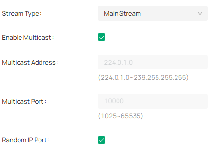
4. Disable Random IP Port and specify a static address and port, or enable Random IP Port.
5. Click Apply.
After Multicast enabled, you can watch the video with the URL rtsp://A:B:C:D/multicastStreamN, for example, rtsp://192.168.0.3/multicastStream1. A.B.C.D is the IP address of the camera, and N can be number 1 or 2 that indicates the stream, 1 for main stream and 2 for substream.
9. 8. 7 Server
You can configure the FTP server to save images which are captured by events.
1. Go to Devices. Select the site where your device is located, find the device in the list, and click ![]() .
.
2. In the panel on the right, go to Network > FTP Settings > Server.
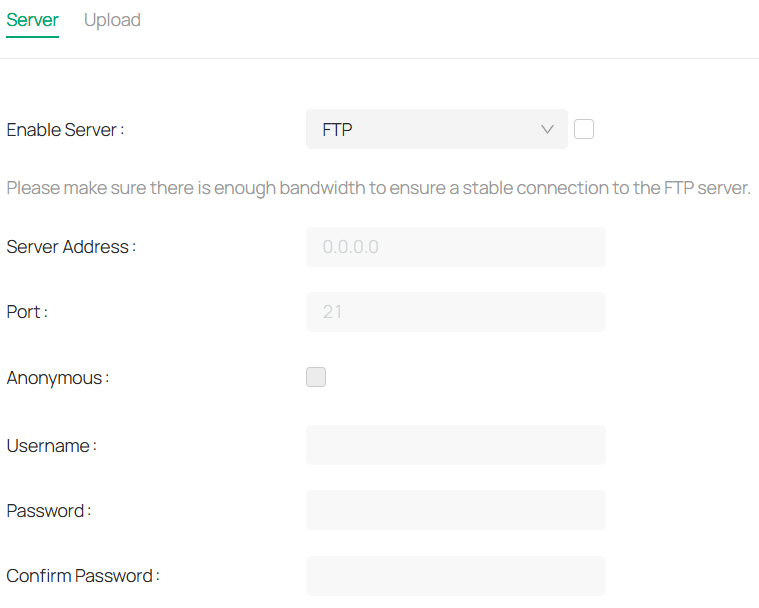
3. Check Enable Server. FTP and SFTP are selectable. The files uploading is encrypted by using SFTP protocol.
4. Enter Server Address and Port. They stand for the FTP server address and corresponding port.
5. Set Username and Password and confirm the password. The FTP user should have the permission to upload pictures.
6. If the FTP server supports picture uploading by anonymous users, you can check Anonymous to hide your device information during uploading.
Note: Anonymous login is not supported when SFTP protocol is selected.
7. Select the saving path of images uploaded in the dropdown box of Upload Path and Edit the Name.
8. Click Test to verify the FTP server.
9. Click Apply.
9. 8. 8 Upload
You can configure the parameters of videos and images to be uploaded to the FTP server.
1. Go to Devices. Select the site where your device is located, find the device in the list, and click ![]() .
.
2. In the panel on the right, go to Network > FTP Settings > Upload.
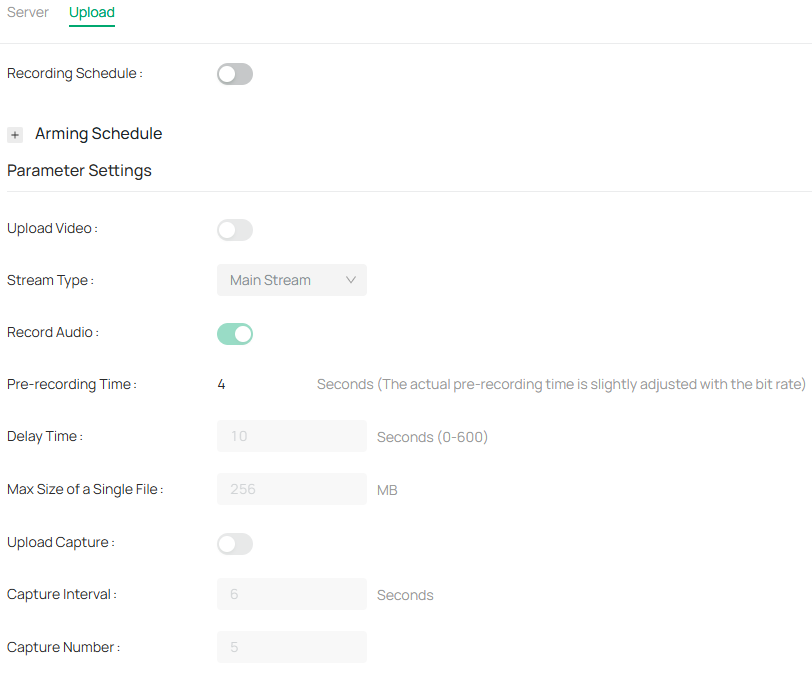
3. Enable Recording Schedule and refer to Arming Schedule and Processing Mode for settings if needed.
4. Enable Upload Video and Upload Capture as needed.
5. Configure the following parameters:
|
Stream Type |
Select the stream type for recording. Main Stream stands for the best stream performance the device supports. It usually offers the best resolution and frame rate the device can do. But high resolution and frame rate usually means larger storage space and higher bandwidth requirements in transmission. Substream usually offers comparatively low resolution options, which consumes less bandwidth |
|---|---|
|
Record Audio |
Enable to record audio and video simultaneously. |
|
Pre-recording Time |
The time period you set to record before the scheduled time. For example, the schedule for continuous recording starts at 10:00. If you set the pre-recording time as 5 seconds, the camera starts to record at 9:59:55. |
|
Delay Time |
The time is set for cameras to record after the scheduled time or event. For example, if you set the post-record time as 5 seconds, it records till 11:00:05 as motion detection ends at 11:00. |
|
Max Size of a Single File |
Set the size limit of a single file. |
|
Capture Interval |
The camera takes the capture when it reaches the capture interval. |
|
Capture Number |
The number of captures taken during one interval. |
6. Click Apply.
9. 8. 9 ONVIF
ONVIF, or Open Network Video Interface Forum, aims to provide a standard for the interface between different IP-based physical security devices. ONVIF specifications provide a consistent way for devices from multiple manufacturers to work together
1. Go to Devices. Select the site where your device is located, find the device in the list, and click ![]() .
.
2. In the panel on the right, go to Network > Advanced > ONVIF.
3. Enable ONVIF if you need to use third-party management devices. For firmware version 1.6 and onwards, ONVIF uses port 80 and 2020 by default for communication; for earlier versions, the default port for ONVIF is 2020.

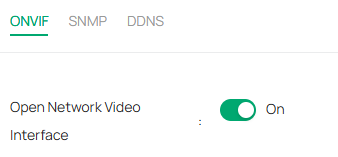
4. Click Apply.
9. 8. 10 SNMP
You can set the SNMP, or Simple Network Management Protocol, to get device information in network management.
1. Go to Devices. Select the site where your device is located, find the device in the list, and click ![]() .
.
2. In the panel on the right, go to Network > Advanced > SNMP.

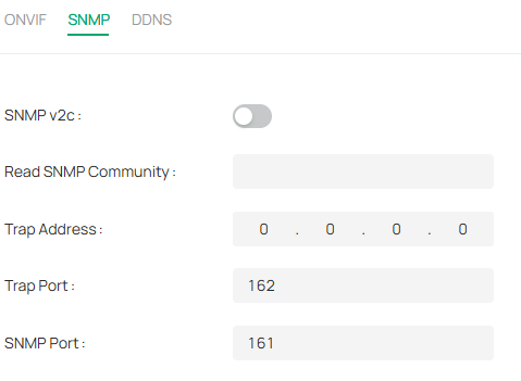
3. Enable SNMP v2c.
4. Enter the SNMP community name. Note that the access is Read only, meaning that the network management system can only view but not modify parameters of the specified view.
5. Configure the following parameters.
|
Trap Address |
IP Address of SNMP host. |
|---|---|
|
Trap Port |
Port of SNMP host. The value is by default 162 and can range from 1 to 65535. |
|
SNMP Port |
An SNMP communication endpoint that identifies SNMP data transfers. By default the SNMP port is 161. |
6. Click Apply.
9. 8. 11 DDNS
You can use the Dynamic DNS (DDNS) for network access. The dynamic IP address of the device can be mapped to a domain name resolution server to realize the network access via domain name. Registration on the DDNS server is required before configuring the DDNS settings of the device.
1. Go to Devices. Select the site where your device is located, find the device in the list, and click ![]() .
.
2. In the panel on the right, go to Network > Advanced > DDNS.

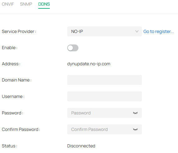
3. Select the type of Service Provider for domain name resolution.
4. Enter the domain name information, and click Apply.
9. 9 System
System settings enable you to configure the basic and advanced settings of your camera, export and import settings. You can create and modify administrator accounts based on your needs.
9. 9. 1 Change Device Name
1. Go to Devices. Select the site where your device is located, find the device in the list, and click ![]() .
.
2. In the panel on the right, go to System > Basic Settings > Basic Settings.
3. View and change the name of your camera.
4. Specify the Web Session Timeout. You will be logged out when you make no operation (not including viewing live image) to the device via web browser within the set timeout period.

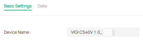
9. 9. 2 Modify Device Time
You can select the time zone and set the time synchronization mode to Manual or NTP mode for the camera.
1. Go to Devices. Select the site where your device is located, find the device in the list, and click ![]() .
.
2. In the panel on the right, go to System > Basic Settings > Date.

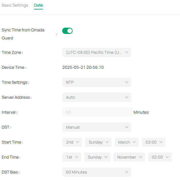
3. Select your time zone.
4. Configure your time settings.
Network Time Protocol (NTP) is a protocol designed to time-synchronize a network of machines. NTP runs on User Datagram Protocol (UDP), which in turn runs on IP, or you can manually set the system time. If you do not want to expose your camera to the network, you can choose Manual.
|
Server address |
Enter the IP address of the NTP server. |
|---|---|
|
Interval |
Time interval between the two synchronizing actions with NTP server. Note: The interval can be set from1 to 10080 minutes, and the default value is 60 minutes. |
5. (Optional) Set DST (daylight saving time) parameters.
DST is the practice of setting the clocks forward one hour from standard time during the summer months, and back again in the fall. DST Bias is the difference in minutes between standard time and daylight-saving time for a specific time zone.
You can select Auto at the dropdown list. Note that to update the time automatically with the DST, internet connection is required.
Or you can select Manual and specify the date/time of the DST period.
Note:
• In some time zones, DST is not observed.
• If the camera is connected to an NVR, you only need to configure NTP and DST settings on the NVR, which will be synchronized with the camera.
6. Click Apply.
9. 9. 3 Change Password
To ensure the security of your network camera, it’s important to periodically update your login credentials. Follow the steps to change the password for your device.
1. Go to Devices. Select the site where your device is located, find the device in the list, and click ![]() .
.
2. In the panel on the right, go to System > User Management > Change Password.

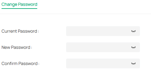
3. Enter the current password, type the new password, and confirm it.
4. Click Apply to save the changes.
9. 9. 4 System Management
You can reset the camera to factory default settings, import and export the configuration file of your camera.
1. Go to Devices. Select the site where your device is located, find the device in the list, and click ![]() .
.
2. In the panel on the right, go to System > System Management > System Management.

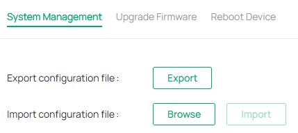
3. To export the configuration file, click Export.
4. To import the configuration file, click Browse to select your file, then click Import.
9. 9. 5 Upgrade Firmware
TP-Link aims at providing better network experience for users. We will inform you through the web management page if there’s any update firmware available for your camera. Also, the latest firmware will be released at the TP-Link official website www.tp-link.com, and you can download it for free.
Note:
1. Backup your camera configuration before firmware upgrade.
2. Do NOT power off the camera during the firmware upgrade.
To upgrade device firmware, follow these steps:
1. Download the latest firmware file for the camera from https://www.tp-link.com/sg/support/download/.
2. Go to Devices. Select the site where your device is located, find the device in the list, and click ![]() .
.
3. In the panel on the right, go to System > System Management > Upgrade Firmware.

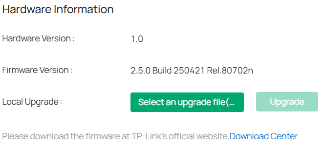
4. Click Browse to locate the downloaded new firmware file, and click Update.
5. Wait a few minutes for the upgrade and reboot to complete.
9. 9. 6 Reboot Device Regularly
The Scheduled Reboot feature cleans the cache to enhance the running performance of the camera.
1. Go to Devices. Select the site where your device is located, find the device in the list, and click ![]() .
.
2. In the panel on the right, go to System > System Management > Reboot Device.

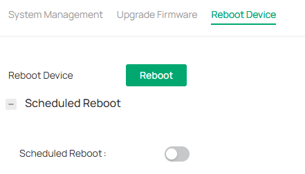
3. Enable Scheduled Reboot.
4. Select the day and time and specify the Float Range. When Fixed Time is selected, the camera will reboot at exactly the time you set in the Reboot Schedule. You may select 1 to 60 minutes. Then your camera will reboot some time before or after the time you set in the Reboot Schedule.
5. Click Apply.
Chapter 10 Cloud Backup
The chapter explains how to manage cloud storage packages for your VMS, ensuring secure and reliable backup of video data. It covers package usage details, cloud backup service settings, and operation logs, helping you monitor backup status, manage device linkages, configure auto-rollover, and track all related activities for streamlined and uninterrupted data protection.
10. 1 Package Usage Details
The Package Usage Details page allows you to monitor and manage your cloud backup packages. It provides an overview of backup statuses, expiration dates, and linked devices, helping you stay on top of your backup health and manage device linkages effectively.
1. Go to Service > Cloud Backup to view the Package Usage Details.
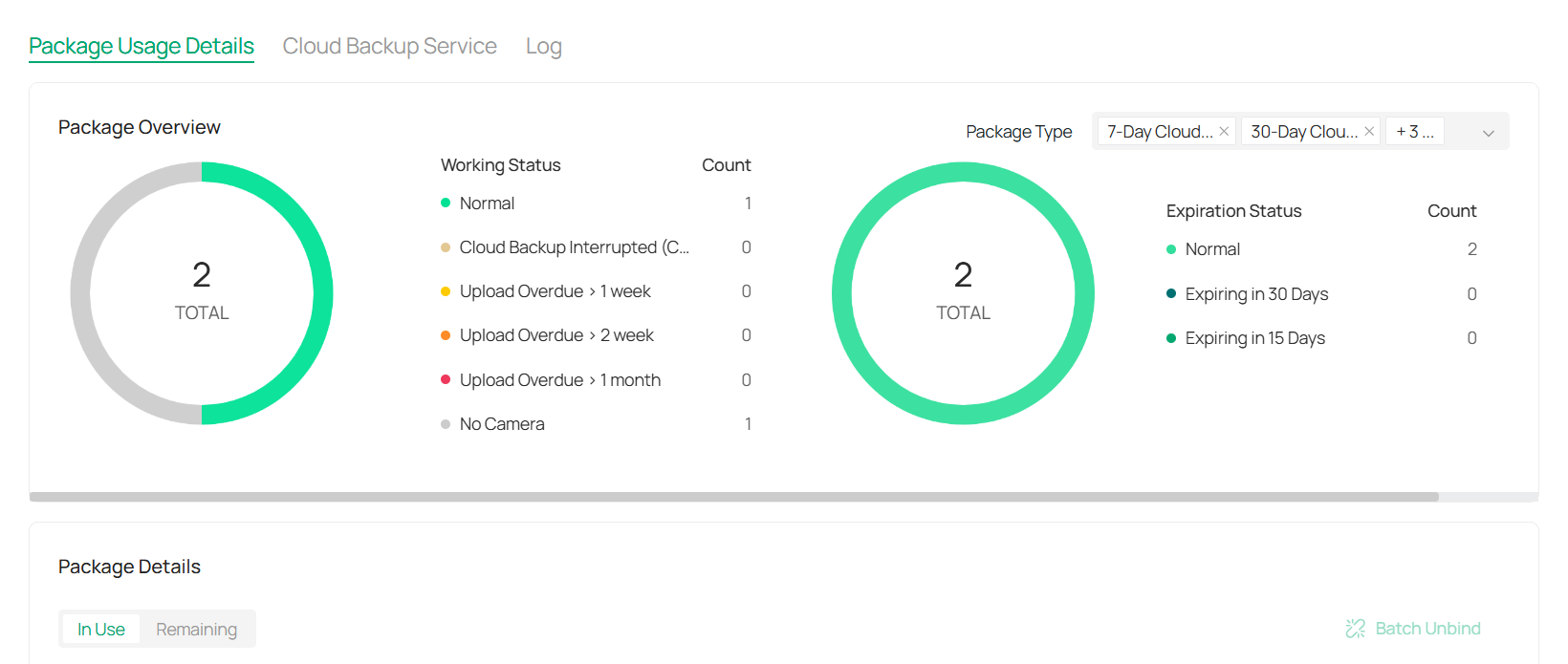
2. Check the Working Status and Expiration Status of all backup packages. Use the Package Type filter to sort by package type.
3. In the Package Details section, you’ll see the linked devices, NVRs, site locations, package types, expiration dates, and available backups. The status of each package is also displayed.
4. (Optional) To change a package, click ![]()
![]() in the Action column. Select a new package from the available options, or click Add New Package, input the license key, and click Apply.
in the Action column. Select a new package from the available options, or click Add New Package, input the license key, and click Apply.
5. To unbind a package, click ![]()
![]() in the Action column and confirm in the pop-up window. You can select multiple devices and click the Batch Unbind button to unbind devices in bulk.
in the Action column and confirm in the pop-up window. You can select multiple devices and click the Batch Unbind button to unbind devices in bulk.
10. 2 Cloud Backup Service
The Cloud Backup Service enables you to manage and assign backup packages for your devices, ensuring secure data storage in the cloud. This page provides an overview of available and activated packages, auto-rollover options, and a detailed operation record to track backup package assignments and modifications.
1. Navigate to Service > Cloud Backup > Cloud Backup Service to view the package overview and manage your backup settings.
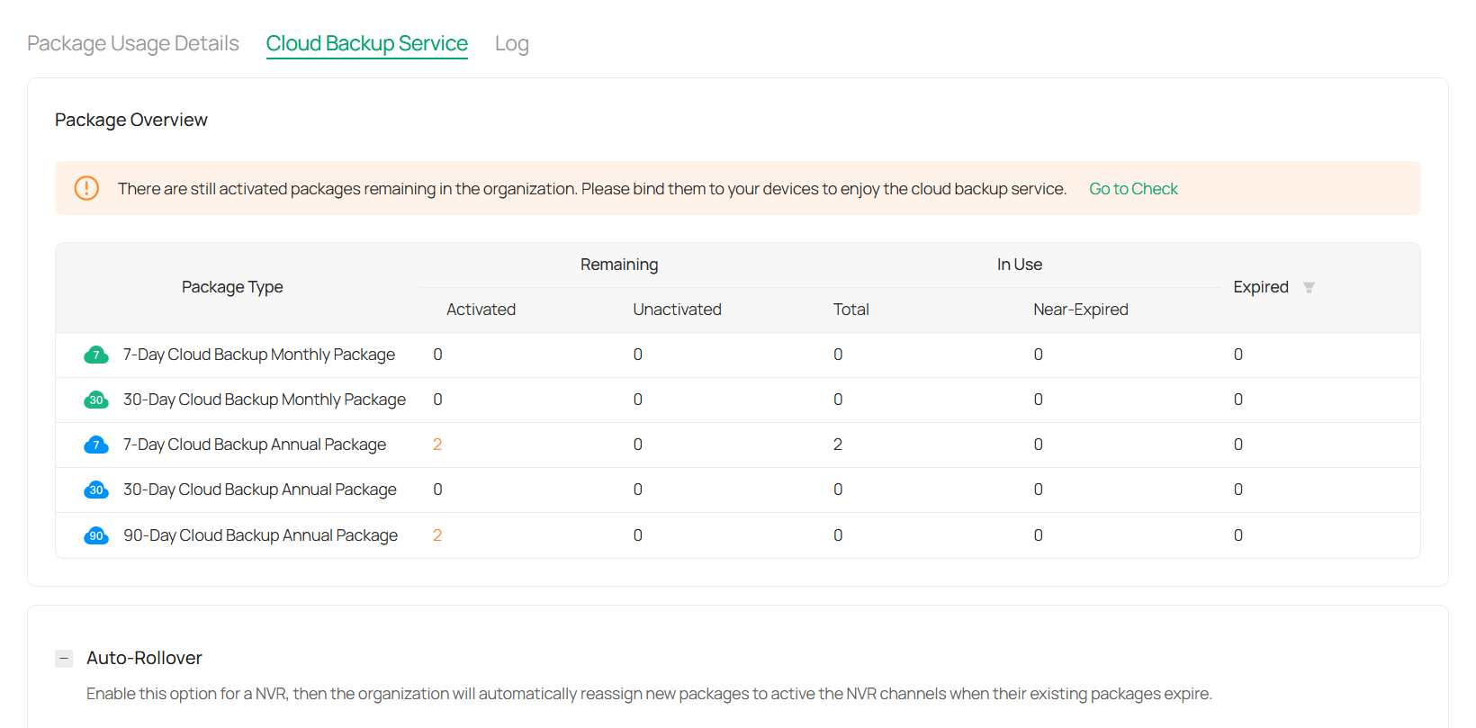
2. In the Package Overview section, you can see the following:
Package Type: Displays the type of backup packages (e.g., 7-Day, 30-Day, 90-Day).
Activated: Shows the number of packages that are active.
Unactivated: Displays the number of unactivated packages.
Remaining: Indicates how many packages are still available for use.
Expired: Lists the expired packages.
Near-Expired: Shows packages that are close to expiration.
You can click on any package type to view further details or manage your packages.
3. Configure Auto-Rollover.
The Auto-Rollover feature automatically assigns new packages to devices when the current ones expire, ensuring continuous backup coverage.
To enable this feature, toggle the Auto-Rollover switch.
4. Review Package Operation Record.
It provides a log of all actions related to backup package assignments. You’ll see:
Operation Type: Displays the action taken (e.g., “Assign”).
Package Quantity: The number of packages assigned.
Operator: The user who performed the action.
Operation Time: The date and time when the action was performed.
10. 3 Cloud Backup Log
The Cloud Backup Log provides a detailed record of all actions performed related to your cloud backup packages. This log helps you track and review every operation, from binding and unbinding packages to package assignments. It is particularly useful for administrators who need to monitor backup package changes, track user activities, and ensure proper package management.
1. To view the Cloud Backup log, navigate to Service > Cloud Backup > Log.
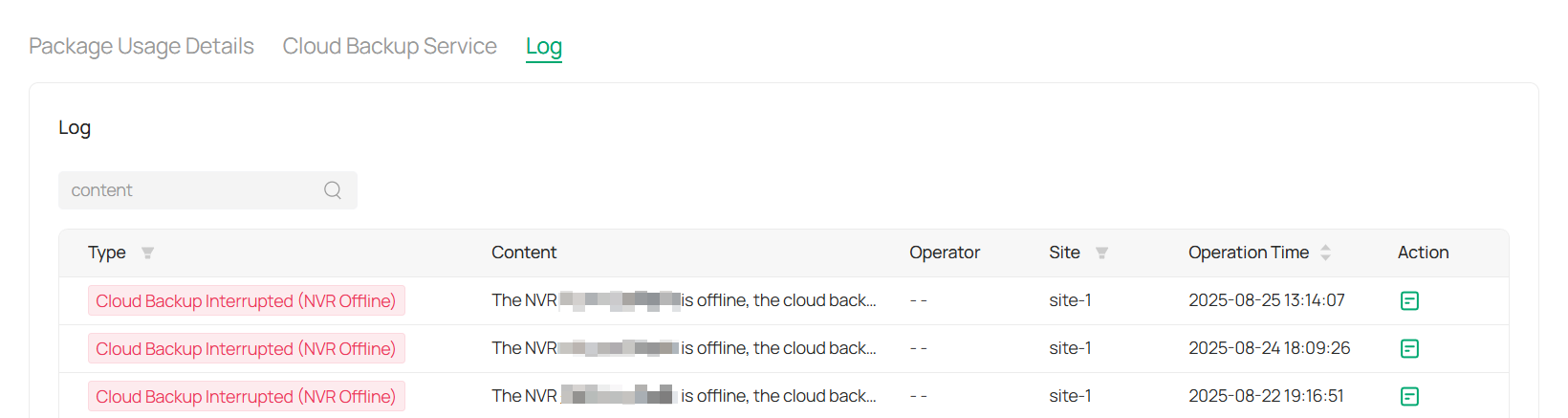
2. View log details.
Type: Describes the type of operation performed (e.g., Bind Package, Unbind Package).
Content: A brief description of the action taken (e.g., “Bound the backup package for camera”).
Operator: The user who performed the action.
Site: The location associated with the operation.
Operation Time: The date and time when the operation was performed.
Action: Provides a link to view more detailed information or manage the operation.
3. Use the Search bar to filter the log by content, operator, or other criteria to find specific actions. This can help you quickly identify important operations or troubleshoot issues.
4. For each operation, you can click ![]()
![]() in the last column to view more details about the action performed.
in the last column to view more details about the action performed.
Chapter 11 Organizations, Sites, and Users
The Organizations, Sites, and Users chapter covers the core administrative settings that define how your VMS is structured and managed. It explains how to configure organization details, create and manage sites, and control user access through roles and permissions. Together, these settings ensure your system is properly aligned across locations, devices, and teams for smooth and secure operation.
11. 1 Organizations
The Organization and Site Settings section allows you to configure essential information for your organization and its sites. Here, you can set up time zones, manage regions, and adjust backup services, ensuring smooth operation across all locations.
1. Go to Admin > Organization Settings to manage your organization’s details.
2. Fill up the required fields.

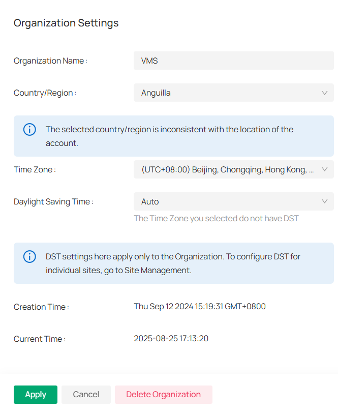
1) Enter Organization Name: Provide the name of your organization.
2) Select Country/Region: Choose the appropriate country or region for your organization.
3) Set Time Zone: Choose the correct time zone for the organization.
4) Configure Daylight Saving Time (DST): Set Auto for automatic handling of DST. Be aware that DST settings are applied only to the organization.
3. Click Apply.
11. 2 Sites
1. Go to Admin > Site Management.
2. Click 
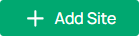 to create a new site.
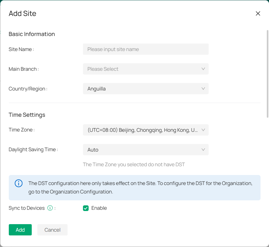
1) Enter Site Name: Define the site’s name.
2) Select Main Branch: Choose the main branch (if applicable).
3) Set Country/Region: Pick the appropriate region for the site.
4) Pick Time Zone: Select the time zone for the site.
5) Enable/Disable DST: Adjust the DST setting as needed for the site.
6) Sync to Devices: Enable to apply DST settings across all devices at the site.
7) Input Location: Add the site’s address, longitude, and latitude (optional).
3. Manage site actions in the site list.
1) Click ![]()
![]() to reorganize the site within your system.
to reorganize the site within your system.
2) Click ![]()
![]() to modify the site’s details like name, region, or time zone.
to modify the site’s details like name, region, or time zone.
3) Click ![]()
![]() to permanently remove the site from your system (be cautious).
to permanently remove the site from your system (be cautious).
11. 3 Users
The Users Management section enables administrators to efficiently manage system users, assign roles, and control site privileges. It provides tools to add new users, modify user roles, and delete users when necessary. The section also offers the flexibility to configure user access levels, ensuring that each user has appropriate permissions based on their role and responsibilities.
■ Add a New User
1. Navigate to Admin > Users.
2. Click ![]()
![]() to create a new user account.
to create a new user account.
3. Fill in the details:
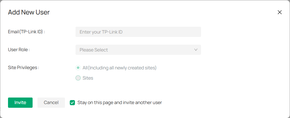
1) Enter the user’s TP-Link ID email.
2) Select the user’s role from the available options (e.g., Owner, Admin, Viewer, etc.).
|
Site Role |
Permission |
|---|---|
|
Super Admin |
Have full access to all resources. |
|
Admin |
Add, manage, and control the devices Preview and play back the videos of a site View and edit site settings |
|
Operator |
Can perform device operations but lacks user and system management permissions. |
|
Viewer |
Preview and play back the videos of a site |
|
Live Only |
Preview the videos of a site |
4) Choose between granting access to All sites (including newly created sites) or specific Sites.
4. After entering the details, click Invite to send an invitation to the user. Optionally, check Stay on this page and invite another user to add multiple users in one session.
■ Manage Existing Users
To manage existing users, go to Admin > Users > Users. In the Action column, click 
![]() to modify user details or
to modify user details or ![]()
 to remove the user from the system.
To view the list of user’s roles, go to Admin > Users > Roles, click ![]()
![]() to see a description of the permissions granted to that role.
to see a description of the permissions granted to that role.

Chapter 12 Maintenance
The Maintenance chapter provides tools for keeping your VMS running smoothly and aligned with organizational needs. It covers how to view and export system and operation logs for auditing, as well as how to adjust system settings such as name, logo, data retention policies, and participation in the user experience program. These options help administrators ensure reliable performance, clear oversight, and a customized system environment.
12. 1 Log
Logs can only be viewed and exported by the organization founder and organization administrator.
Go to Admin > Log. You can view both the operation log and the system log.
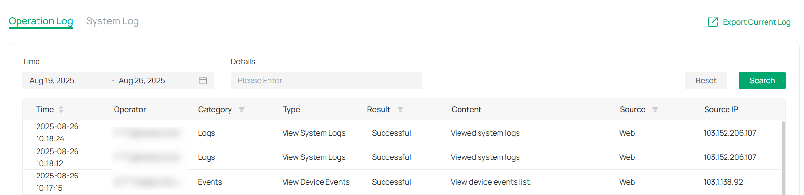
■ Search for Log
To search for the needed logs, enter key words. You may filter logs by time range. Then click Search.

■ Export Log
To export the logs, click Export Current Log.

12. 2 System Settings
In System Settings, you can configure your system’s name, logo, data retention, and participation in the user experience program, ensuring the system aligns with your organization’s needs.
Go to Admin > System Settings.
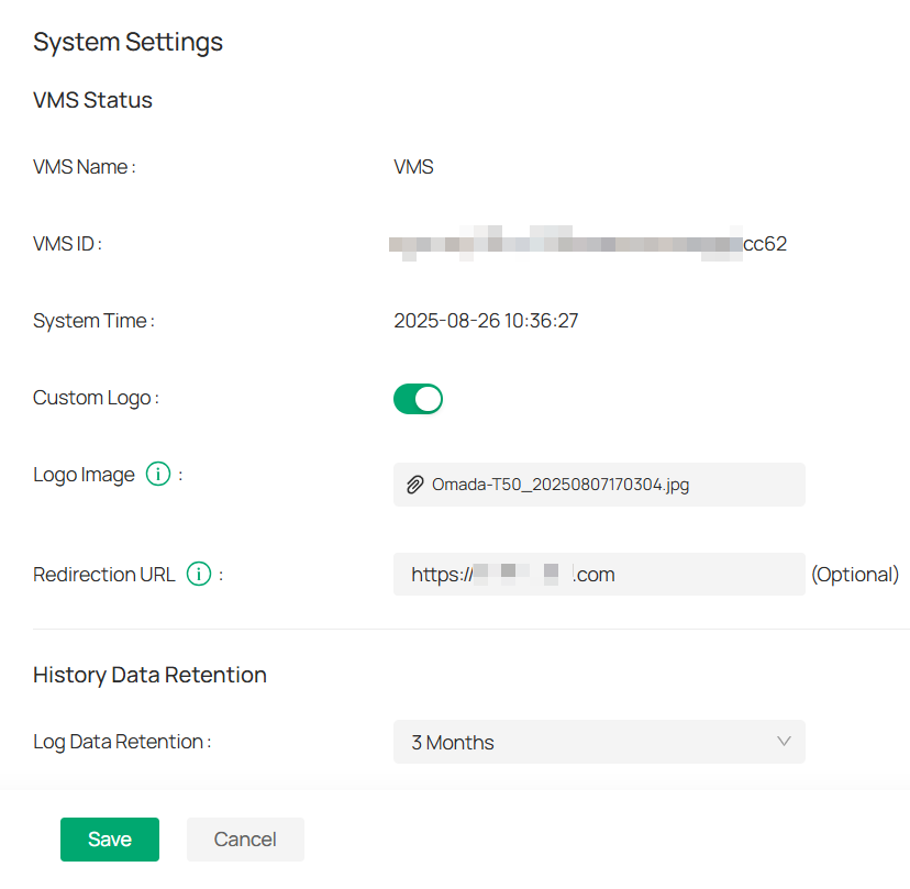
1. Set VMS details.
1) Enter VMS Name: Define the name of your VMS.
2) View VMS ID: The system automatically generates this unique identifier.
3) Adjust System Time: Update the time to match your region.
2. Customize your logo.
1) Enable Custom Logo: Toggle to add your brand’s logo.
2) Upload Logo: Select and upload your custom logo image.
3) Add Redirection URL (Optional). When click the logo on web portal, it will redirect to the URL you set.
3. Manage data retention.
1) Set Log Data Retention: Define how long log data is stored.
2) Set Event Data Retention: Decide how long event data is retained.
3) Set Alert Data Retention: Specify the duration for storing alert data.
4. Join the experience program (Optional). You can withdraw from the program whenever needed.
5. Attach alarm images as needed. When enabled, the device will attach an alarm thumbnail when uploading alarm information to VMS.