Table of Contents
Installation Guide for Unmanaged/Easy Smart Rackmountable Switches (Multi_Model)
About this Installation Guide
This Installation Guide describes the hardware characteristics, installation methods and the points that should be attended to during installation. This Installation Guide is structured as follows:
Chapter 1 Introduction
This chapter describes the external components of the switch.
Chapter 2 Installation
This chapter illustrates how to install the switch.
Chapter 3 Connection
This chapter illustrates how to do the physical connection of the switch.
Appendix A Troubleshooting
Appendix B Hardware Specifications
Audience
This Installation Guide is for:
Network Engineer Network Administrator
Conventions
When using this guide, notice that features available in JetStream series products may vary by model and software version. Availability of JetStream series products may also vary by region or ISP. All images, steps, and descriptions in this guide are only examples and may not reflect your actual experience. Some models featured in this guide may be unavailable in your country or region. For local sales information, visit https://www.tp-link.com.
The speed of the ports in Extend Mode will downgrade to 10 Mbps. The actual transmissio distance may vary due to power consumption of PoE-powered devices or the cable quality and type.
PoE budget calculations are based on laboratory testing. Actual PoE power budget is not guaranteed and will vary as a result of client limitations and environmental factors.
 |
Remind to be careful. A caution indicates a potential which may result in device damage. |
 |
Remind to take notice. The note contains the helpful information for a better use of the product. |
Related Document
This Installation Guide is also available in PDF on our website. To obtain the latest documentation and product information, visit the official website: https://www.tp-link.com.
Chapter 1 Introduction
1.1 Product Overview
The Unmanaged/Easy Smart Switch provides you with a low-cost, easy-to-use, high-performance, seamless, and standard upgrade to improve your network to 100 Mbps or 1000 Mbps.
TL-SG1008MP/TL-SG1016PE/TL-SG1218MP/TL-SG1218MPE/TL-SG1428PE is also a Power Sourcing Equipment (PSE*). The RJ45 port 1–8 on TL-SG1008MP and TL-SG1016PE, 10/100/1000 Mbps RJ45 port 1–16 on TL-SG1218MP and TL-SG1218MPE, and 10/100/1000 Mbps RJ45 port 1–24 on TL-SG1428PE support the Power over Ethernet (PoE*) function, which can automatically detect and supply power to those powered devices (PDs*) complying with IEEE 802.3af and IEEE 802.3at.
 Note:
Note:
1. PSE is a device (switch or hub for instance) that will provide power in a PoE setup.
2. PoE is a technology that describes a system to transmit electrical power, along with data, to remote devices over standard twisted-pair cable in an Ethernet network.
3. PD is a device powered by a PSE and thus consumes energy. Examples include powering IP telephones, wireless LAN access points, network cameras, network hubs, embedded computers, and so on.
1.2 Appearance
1.2.1 Front Panel
The front panel of TL-SG1008 is shown as the following figure.
The front panel of TL-SG1008MP is shown as the following figure.
_4.0前面板-01_20251128105907z.png)
The front panel of TL-SF1016 is shown as the following figure.
The front panel of TL-SF1016DS is shown as the following figure.
The front panel of TL-SG1016 is shown as the following figure.
The front panel of TL-SG1016D is shown as the following figure.
_7.0前面板-01_20251128110027z.png)
The front panel of TL-SG1016S is shown as the following figure.
The front panel of TL-SG1016DE is shown as the following figure.
_3.0前面板-01_20251128110103j.png)
The front panel of TL-SG1016PE is shown as the following figure.
_1.0前面板-01_20251128110120w.png)
The front panel of TL-SF1024 is shown as the following figure.
The front panel of TL-SF1024D is shown as the following figure.
The front panel of TL-SG1024 is shown as the following figure.
The front panel of TL-SG1024D is shown as the following figure.
_11.0前面板-01_20251128110202e.png)
The front panel of TL-SG1024S is shown as the following figure.
The front panel of TL-SG1024DE is shown as the following figure.
_7.0前面板-01_20251128110235w.png)
The front panel of TL-SF1048 is shown as the following figure.
The front panel of TL-SG1048 is shown as the following figure.
The front panel of TL-SG1218MP is shown as the following figure.
_5.0_前面板图-01_20251128110353k.png)
The front panel of TL-SG1218MPE is shown as the following figure.
_2.0_前面板图-01_20251128110414x.png)
The front panel of TL-SG1428PE is shown as the following figure.
1.0_前面板(带文字)-01_20251128110437a.png)
| LED | Indication |
|---|---|
| Power PWR |
On: The switch is powered on. Off: The switch is powered off or power supply is abnormal. Flashing: Power supply is abnormal/Loop Prevention function is enabled. Note: PWR for TL-SG1016PE/TL-SF1024/TL-SG1218MP/TL-SG1218MPE/TL-SG1428PE; Power for other switches. |
| 1000Mbps | On: Running at 1000 Mbps. Off: Running at 10/100 Mbps or no device is linked to the corresponding port. Note: For TL-SG1008/TL-SG1008MP/TL-SG1016/TL-SG1016D/TL-SG1016S/ TL-SG1016DE/TL-SG1024/TL-SG1024D/TL-SG1024S/TL-SG1024DE. |
| Speed | Green On: Running at 1000 Mbps but no activity. Green Flashing: Running at 1000 Mbps and is transmitting or receiving data. Yellow on: Running at 100/10 Mbps but no activity. Yellow Flashing: Running at 100/10 Mbps and is transmitting or receiving data. Off: No device is linked to the corresponding port. Note: Only for TL-SG1016PE. |
| Link/Act | On: A device is linked to the corresponding port and running properly. Flashing: Transmitting or receiving data. Off: No device is linked to the corresponding port. Note: For TL-SG1008/TL-SG1008MP/TL-SF1016/TL-SG1016/TL-SG1016D/TL-SG1016S/TL-SF1016DS/TL-SG1016DE/TL-SF1024/TL-SF1024D/TL-SG1024/TL-SG1024D/TL‑SG1024S/TL-SG1024DE/TL-SF1048. Green On: Running at 1000 Mbps but no activity. Green Flashing: Running at 1000 Mbps and is transmitting or receiving data. Yellow on: Running at 100/10 Mbps but no activity. Yellow Flashing: Running at 100/10 Mbps and is transmitting or receiving data. Off: No device is linked to the corresponding port. Note: For TL-SG1048, port 1–18 of TL-SG1218MP/TL-SG1218MPE, and port 1–26 of TL-SG1428PE. Port 17F–18F of TL-SG1218MP/TL-SG1218MPE, and port 27–28 of TL-SG1428PE only support 1000M SFP module connection, and they just have Green On/Green Flashing/Off LED indications |
| PoE Status | On: The port is connecting and supplying power to a PD. Flashing: The PoE power circuit may be in short or the power current may be overloaded or non-standard PD is connected or the amount of power of the port has exceeded the power limit. Off: No PD is connected to the corresponding port or no power is supplied according to the power limits of the port. Note: For TL-SG1008MP/TL-SG1016PE/TL-SG1218MP/TL-SG1218MPE/TL-SG1428PE |
| FAN | Green: The fan works properly. Yellow: The fan doesn’t work properly. Note: For TL-SG1218MP/TL-SG1218MPE/TL-SG1428PE |
| PoE Max | On: Total power supply is between 146 W and 153 W. No power may be supplied if additional PDs are connected. Flashing: Total power supply is equal to or greater than 153 W. Off: Total power supply is less than 146 W. Note: Only for TL-SG1008MP. On: Total power supply is between 143 W and 150 W. No power may be supplied if additional PDs are connected. Flashing: Total power supply is equal to or greater than 150 W. Off: Total power supply is less than 143 W. Note: Only for TL-SG1016PE. On: Total power supply is equal to or greater than 243 W. Flashing: Total power supply is equal to or greater than 243 W and lasts for more than 2 minutes. Off: Total power supply is less than 243 W. Note: For TL-SG1218MP/TL-SG1218MPE/TL-SG1428PE |
Note:
For models that support the LED On/Off feature, the LEDs function as shown above only when the LED status is on.
Switch Explanation
| Switch | Indication |
|---|---|
| Priority (For TL-SG1218MP) |
Off: All the ports transmit data with the same priority. On: The specific ports transmit data with a higher priority than other ports. |
| Isolation (For TL-SG1218MP/TL-SG1016/TL-SG1016D/TL-SG1024/TL-SG1024D/TL-SG1024S) |
Off: Ports can transmit data with each other. On: Specific ports cannot transmit data with other downlink ports. They can transmit data only with the uplink ports. |
| Extend (For TL-SG1008MP/TL-SG1218MP) |
Off: Ports run at 10/100/1000 Mbps and support PoE power supply up to 100 m away. On: Ports run at 10 Mbps and support PoE power supply up to 250 m away. |
| Recovery (For TL-SG1008MP/TL-SG1218MP) |
Off: The PoE Auto Recovery function is disabled. On: The switch will constantly detect the working status of a PoE powered device (PD). When the switch finds that the PD works abnormally, the switch will reboot it. |
| Loop Prevention (For TL-SG1016/TL-SG1016D/TL-SG1024/TL-SG1024D/TL-SG1024S) |
Off: (default) The switch will not try to monitor or address loop-related issues. On: The switch will monitor and address loop-related issues within the network structure to prevent disruptions caused by redundant pathing. |
Note:
The numbers in brackets indicate the ports where the feature takes effect. For example, when Extend(1-4) is toggled to On, the Extend mode will be enabled for ports 1-4.
Reset
Press this button for five seconds or above to reset the switch back to factory default settings.
Note:
Only TL-SG1016DE/TL-SG1016PE/TL-SG1024DE/TL-SG1218MPE/TL-SG1428PE has a Reset button.
10/100/1000Mbps RJ45 Port
Designed to connect to the device with a bandwidth of 10 Mbps, 100 Mbps or 1000 Mbps. For TL‑SG1008MP and TL‑SG1016PE, port 1–8 can provide power for PDs. For TL-SG1218MP and
TL-SG1218MPE, port 1–16 can provide power for PDs. For TL-SG1428PE, port 1–24 can provide power for PDs.
10/100Mbps RJ45 Port
Designed to connect to the device with a bandwidth of 10 Mbps or 100 Mbps.
SFP Slot
Designed to install the SFP module. TL-SG1218MP/TL-SG1218MPE/TL-SG1428PE has 2 SFP slots which support 1000 Mbps SFP module connection. For TL-SG1218MP and TL-SG1218MPE, an SFP Slot (port 17F/port 18F) and the associated 10/100/1000 Mbps RJ45 Port (port 17/port 18) are called a “Combo” port, which means they cannnot be used simultaneously.
1.2.2 Rear Panel
The rear panel is shown as the following figure. Here we take TL-SG1016PE as an example.
_1.0后面板-01_20251128035020v.png)
Kensington Security Slot
Secure the lock (not provided) into the security slot to prevent the device from being stolen.
Note:
Only TL-SG1016PE/TL-SG1218MP/TL-SG1218MPE/TL-SG1024/TL-SG1428PE has a kensington security slot.
Grounding Terminal
The switch already comes with lightning protection mechanism. You can also ground the switch through the PE (Protecting Earth) cable of AC cord or with Ground Cable. For detailed information, refer to the Lightning Protection Guide from the Related Documents of our website:
https://www.tp-link.com/us/configuration-guides/lightning_protection_guide.
Power Socket
Plug the female connector of the power cord directly into the power socket and plug the male connector into an AC outlet. Make sure that the voltage of the power supply meets the requirement of the input voltage (100–240 V ~ 50/60 Hz).
Caution: You should use the provided power cord.
Chapter 2 Installation
2.1 Package Contents
Make sure that the package contains the following items. If any of the listed items is damaged or missing, contact your distributor. The figures are for demonstration only. The actual items may differ in appearance and quantity from the depicted.
|
One switch  |
One power cord -01_20251128054722d.png) |
|
This installation guide
|
Mounting brackets, screws and rubber feet
|

2.2 Safety Precautions
To avoid any device damage and bodily injury caused by improper use, you should observe the following rules.
Safety Precautions
• Keep the power off during the installation.
• Wear an ESD-preventive wrist strap, and make sure that the wrist strap has a good skin contact and is well grounded.
• Use only the power cord provided with the switch.
• Make sure that the supply voltage matches the specifications indicated on the rear panel of the switch.
• Ensure that the switch is installed in a well-ventilated environment and its ventilation hole is not blocked.
• Do not open or remove the cover of the switch.
• Before cleaning the device, cut off the power supply. Do not clean it by the waterish cloth, and never use any other liquid cleaning method.
• Place the device with its bottom surface downward.
Site Requirements
Temperature/Humidity
Keep the equipment room at an appropriate level of temperature and humidity. Too much or too little humidity may lead to bad insulation, leakage of electricity, mechanical property changes, and corrosion. High temperatures may accelerate aging of the insulation materials, significantly shortening the service life of the device. To find out the best temperature and humidity conditions for the device, check Appendix B.
Clearness
• The dust accumulated on the switch can be absorbed by static electricity and result in poor contact of metal contact points. Some measures have been taken for the device to prevent static electricity, but too strong static electricity can cause deadly damage to the electronic elements on the internal circuit board. To avoid the effect of static electricity on the operation of the switch, attach much importance to the following items:
• Dust the device regularly, and keep the indoor air clean.
• Keep the device well grounded and ensure that the static electricity has been transferred.
Electromagnetic Interference
• Electronic elements including capacitance and inductance on the device can be affected by external interferences, such as conducted emission by capacitance coupling, inductance coupling, and impedance coupling. To decrease the interferences, make sure to take the following measures:
• Use the power supply that can effectively filter interference from the power grid.
• Keep the device far from high-frequency and strong-current devices such as radio transmitting station.
• Use electromagnetic shielding when necessary.
Lightning Protection
• Extremely high voltage currents can be produced instantly when lightning occurs and the air in the electric discharge path can be instantly heated up to 20,000 °C. As this instant current is strong enough to damage electronic devices, more effective lightning protection measures should be taken.
• Ensure that the rack and the device are well earthed.
• Make sure the power socket has a good contact with the ground.
• Keep a reasonable cabling system and avoid induced lightning.
• Use the signal SPD (Surge Protective Device) when wiring outdoor.
Note:
For detailed lightning protection measures, refer to the Lightning Protection Guide from the Related Documents of our website:
https://www.tp-link.com/us/configuration-guides/lightning_protection_guide.
Installation Site
• When installing the device on a rack or a flat workbench, attach much importance to the following items:
• The rack or workbench is flat, stable, and sturdy enough to support the weight of 5.5 kg at least.
• The rack or workbench has a good ventilation system. The equipment room is well ventilated.
• The rack is well grounded. Keep the device less than 1.5 meters away from the power socket.
2.3 Installation Tools
• Phillips screwdriver
• ESD-preventive wrist wrap
• Cables
Note:
These tools are not included with our product. If needed, you can purchase them separately.
2.4 Product Installation
Desktop Installation
To install the device on the desktop, follow the steps:
1. Set the device on a flat surface which is strong enough to support the entire weight of the device with all fittings.
2. Remove the adhesive backing papers from the rubber feet.
3. Turnover the device and attach the supplied rubber feet to the recessed areas on the bottom at each corner of the device.
Rack Installation
To install the device in an EIA standard-sized, 19-inch rack, follow the instructions described below:
1. Check the efficiency of the grounding system and the stability of the rack.
2. Secure the supplied rack-mounting brackets to each side of the device with supplied screws, as illustrated in the following figure.
3. After the brackets are attached to the device, use suitable screws (not provided) to secure the brackets to the rack, as illustrated in the following figure.
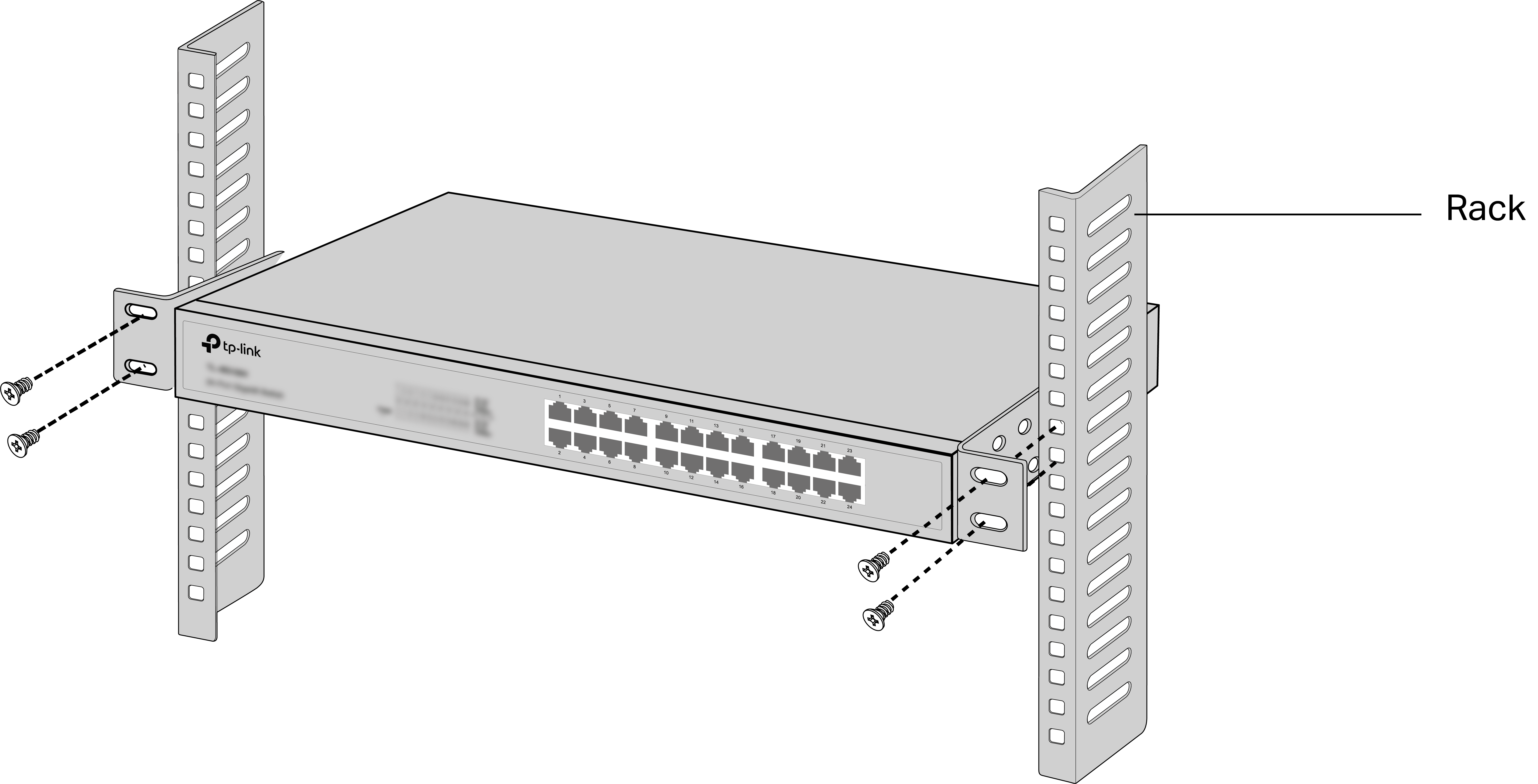
 Caution:
• Leave 5 to 10 cm gaps around the devices for air circulation.
• Avoid placing heavy things on the device.
• Mount devices in sequence from the bottom to top of the rack and ensure a certain clearance between devices for the purpose of heat dissipation.
Chapter 3 Connection
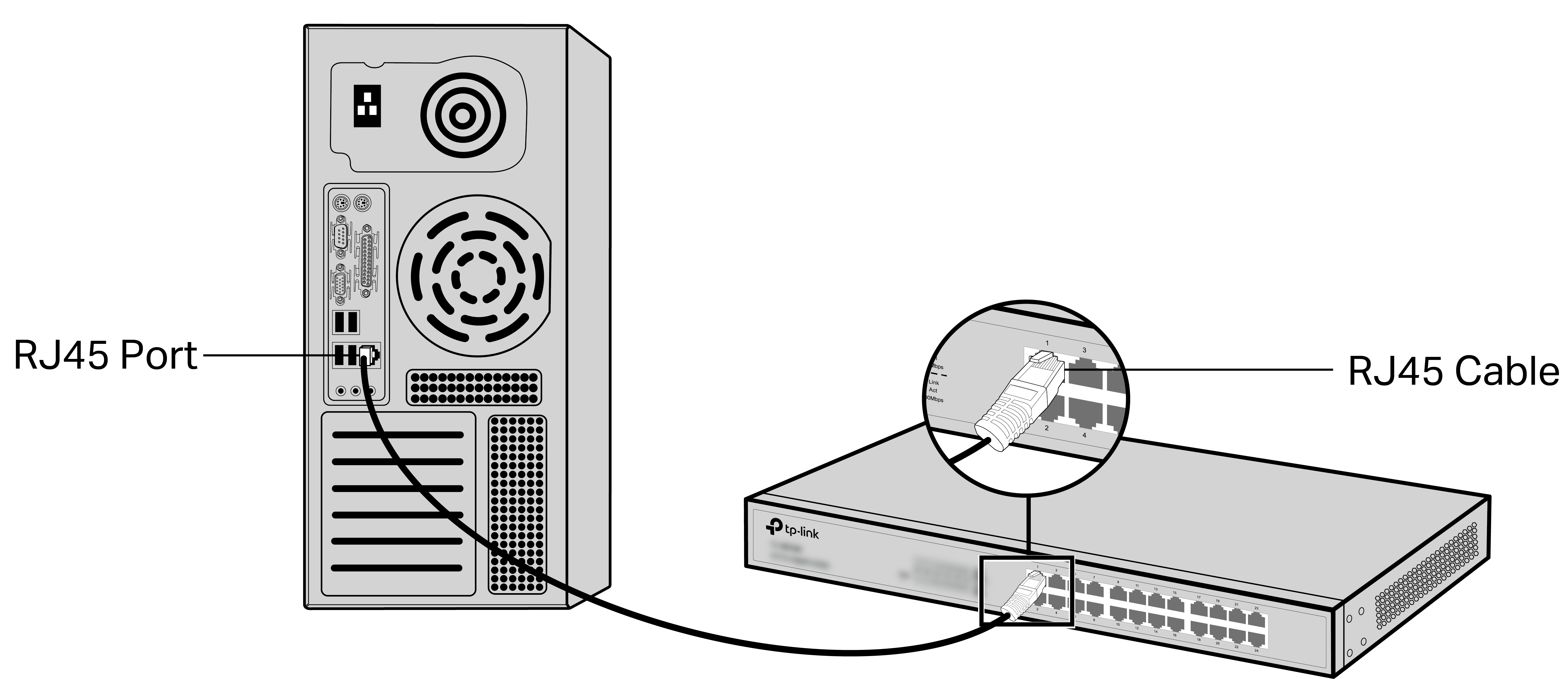
3.1 Ethernet Port
Connect an Ethernet port of the switch to the computer by RJ45 cable as the following figure shows.
3.2 SFP Port
The following figure demonstrates the connection of SFP slot to an SFP module.

Note:
TL-SG1218MP/TL-SG1218MPE/TL-SG1428PE has 2 SFP slots which support 1000 Mbps SFP module connection.
3.3 Verify Installation
After completing the installation, verify the following items:
• There should be 5 to 10 cm of clearance around the device for ventilation and make sure the air flow is adequate.
• The voltage of the power supply meets the requirement of the input voltage of the device.
• The power socket, device and rack are well grounded.
• The device is correctly connected to other network devices.
3.4 Power On
Plug the negative connector of the provided power cord into the power socket of the device and plug the positive connector into a power outlet as the following figure shows.
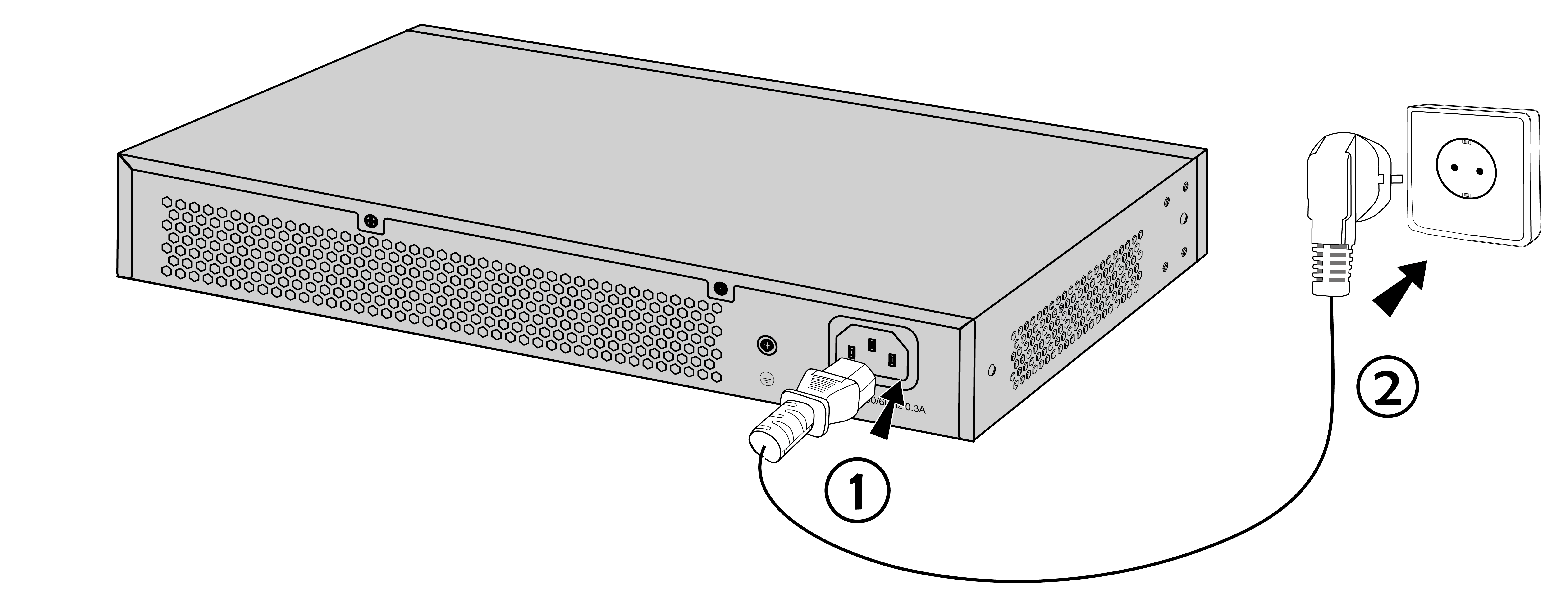
Note:
The figure is to illustrate the application and principle. The provided plug and the socket in your region may differ from the figures above.
3.5 Initialization
After the device is powered on, it begins the Power-On Self-Test. A series of tests run automatically to ensure the device functions properly. During this time, the LED indicators will respond as follows:
1. The PWR/Power LED indicator will light up.
2. The LED indicators of all the ports will flash momentarily and then turn off again after the initialization.
3.6 Accessing the Switch
Note:
• Only for TL-SG1016DE/TL-SG1016PE/TL-SG1024DE/TL-SG1218MPE/TL-SG1428PE, you can access and manage the switch.
• After the initialization finished, you can access and manage the switch using the Web-based GUI (Graphical User Interface) or using the Configuration Utility.
Using the Web-Based GUI
To access and manage the switch using the Web-Based GUI, take the following steps:
1. Find the IP address of the switch.
• By default, the switch receives an IP address from a DHCP server (or a router that functions as a DHCP server) in your network. You can find out this IP address on the DHCP server.
• If the switch cannot receive an IP address from a DHCP server, it uses the static IP address of 192.168.0.1, with a subnet mask of 255.255.255.0.
2. Configure IP address on your PC to make sure the switch and PC are in the same subnet.
• If the switch uses an IP address assigned by a DHCP server, set your PC to obtain an IP address automatically from the DHCP server.
• If the switch uses 192.168.0.1 as the IP address, set your PC’s IP address as 192.168.0.x (”x” ranges from 2 to 254), and subnet mask as 255.255.255.0.
3. Launch a web browser on your PC, enter the IP address of the switch in the address bar and press Enter. Before proceeding with further configuration, you need to set up username and password by following the prompts on the page (if prompted to log in before setting username and password, use admin for both the username and password).
Note:
• For certain devices, you may need to change the password the first time you log in, which will better protect your network and devices.
• Now you can configure the switch using the Web-based GUI. For further information, refer to the User Guide. Go to https://www.tp-link.com/support, search the model number of your switch, and you can find this guide on the product Support web page.
Using the Configuration Utility
• To find the configuration utility from the official website, go to https://www.tp-link.com/support and search the model number of your switch. Download the Easy Smart Configuration Utility from the product Support web page on your PC.
• For further information, refer to the Easy Smart Configuration Utility User Guide. Go to https://www.tp-link.com/support, search the model number of your switch, and you can find this guide on the product Support web page.
Appendix A Troubleshooting
Q1. What could I do if I forgot the username and password of the Switch?
With the switch powered on, press the Reset button for at least 5 seconds to reset the system. The system will be reset to the factory default settings. Set up username and password by following the prompts on the page (if prompted to log in before setting username and password, use admin for both the username and password).
Q2. What should I do if I cannot access the web management page?
Please try the following:
1. Check every port LED on the switch and make sure the Ethernet cable is connected properly.
2. Try another port on the switch and make sure the Ethernet cable is suitable and works normally.
3. Power off the switch and, after a while, power it on again.
4. Make sure the IP address of your PC is set within the subnet of the switch.
5. If you still cannot access the configuration page, please reset the switch to its factory defaults. Then the IP address of your PC should be set as 192.168.0.x ("x" is any number from 2 to 254) and subnet mask as 255.255.255.0.
Q3. Why is the Power/PWR LED not lit?
By default, the Power/PWR LED should be lit when the power system is working normally. If the Power/PWR LED is not lit, please try the following:
1. Make sure that the power cable is connected properly, and the power contact is normal.
2. Make sure the voltage of the power supply meets the requirement of the input voltage of the switch.
3. Make sure the power source is ON.
(For models that support the LED On/Off feature) On the LED On/Off configuration page, check whether the LED status is on. By default, the LED status is on.
Q4. Why is the Link/Act LED not lit while a device is connected to the corresponding port?
Please try the following:
1. Make sure that the cable connectors are firmly plugged into the switch and the device.
2. Make sure the connected device is turned on and working normally.
3. The cable length should be less than 100 meters (328 feet). For TL-SG1008MP/TL-SG1016PE/TL-SG1218MP/TL-SG1218MPE/TL-SG1428PE, if Extend Mode is enabled, it should be less than 250 meters (820 feet).
(For models that support the LED On/Off feature) On the LED On/Off configuration page, check whether the LED status is on. By default, the LED status is on.
Q5. What should I notice before using the PoE Auto Recovery feature?
1. Before upgrading a connected PoE powered device (PD), disable PoE Auto Recovery to avoid the PD’s damage.
2. When a PD does not send data packets to the switch for a long period in certain scenarios (e.g. an IPC in sleep mode), disable PoE Auto Recovery to avoid the PD repeatedly rebooting.
Appendix B Specifications
| Item | Content |
|---|---|
| Standards | IEEE 802.3i, IEEE 802.3u, IEEE 802.3x IEEE 802.3ab (except TL-SF1016/TL-SF1016DS/TL-SF1024/TL-SF1024D/TL‑SF1048) IEEE 802.1p (for TL-SG1008/TL-SG1008MP/TL-SG1016/TL-SG1016D/TL‑SG1016DE/TL-SG1016PE/TL-SG1016S/TL-SG1024/TL-SG1024D/TL‑SG1024DE/TL-SG1024S/TL-SG1218MP/TL-SG1218MPE/TL-SG1428PE) IEEE 802.1q (for TL-SG1016DE/TL-SG1016PE/TL-SG1024DE/TL-SG1218MPE/TL-SG1428PE) IEEE 802.3af (for TL-SG1008MP/TL-SG1016PE/TL-SG1218MP/TL-SG1218MPE/TL-SG1428PE) IEEE 802.3at (for TL-SG1008MP/TL-SG1016PE/TL-SG1218MP/TL-SG1218MPE/TL-SG1428PE) IEEE 802.3z (for TL-SG1218MP/TL-SG1218MPE/TL-SG1428PE) |
| Transmission Medium | 10Base-T: 2-pair UTP/STP of Cat. 3 or above (maximum 100 m) 100Base-TX: 2-pair UTP/STP of Cat. 5 or above (maximum 100 m) 1000Base-T: 4-pair UTP/STP of Cat. 5e or above (maximum 100 m) (except TL‑SF1016/TL-SF1016DS/TL-SF1024/TL-SF1024D/TL‑SF1048) 1000BASE-SX: 62.5 μm MMF (Minimum range: 2 m to 275 m) or 50 μm MMF (Minimum range: 2 m to 550 m) (for TL-SG1218MP/TL-SG1218MPE/TL-SG1428PE) 1000BASE-LX: 62.5 μm/50 μm MMF (Minimum range: 2 m to 550 m) or 10 μm SMF (Minimum range: 2 m to 5000 m) (for TL-SG1218MP/TL-SG1218MPE/TL-SG1428PE) 1000BASE-LX10: Type B1.1, B1.3 SMF (2 fiber) (Minimum range: 0.5 m to 10000 m) (for TL-SG1218MP/TL-SG1218MPE/TL-SG1428PE) 1000BASE-BX10: Type B1.1, B1.3 SMF (1 fiber) (Minimum range: 0.5 m to 10000 m) (for TL-SG1218MP/TL-SG1218MPE/TL-SG1428PE) |
| Frame Forward Rate | 10Base-T: 14881 pps/Port 100Base-X: 148810 pps/Port 1000Base-T: 1488095 pps/Port (except TL-SF1016/TL-SF1016DS/TL-SF1024/TL‑SF1024D/TL‑SF1048) 1000BASE-X: 1488095 pps/Port (for TL-SG1218MP/TL-SG1218MPE/TL-SG1428PE) |
| LEDs | Power, Link/Act (for TL-SF1016/TL-SF1016DS/TL-SF1024/TL-SF1024D/TL‑SF1048/TL-SG1048) Power, 1000 Mbps, Link/Act, PoE Status, PoE MAX (for TL-SG1008MP) PWR, Speed, PoE Status, PoE MAX (for TL-SG1016PE) PWR, Link/Act, PoE Status, PoE MAX, FAN (for TL-SG1218MP/TL-SG1218MPE/TL-SG1428PE) Power, 1000 Mbps, Link/Act (for other switches) |
| Operating Temperature | 0°C to 50°C (32°F to 122°F) (for TL-SG1218MP/TL-SG1218MPE/TL-SG1428PE) 0°C to 45°C (32°F to 113°F) (for TL-SG1008MP/TL-SG1016PE) -5°C to 50°C (23°F to 122°F) (for TL-SG1016D) 0°C to 40°C (32°F to 104°F) (for other switches) |
| Storage Temperature | -40°C to 70°C (-40°F to 158°F) |
| Operating Humidity | 10% to 90%RH Non-condensing |
| Storage Humidity | 5% to 90%RH Non-condensing |
Regulatory Compliance
FCC compliance information statement
![]()
Product Name: Switch
Model Number: TL-SF1016/TL-SF1016DS/TL-SF1024/TL-SF1024D/TL-SF1048/TL-SG1008/TL-SG1008MP/TL-SG1016/TL-SG1016D/TL-SG1016DE/TL-SG1016PE/TL-SG1024/TL-SG1024D/TL-SG1024DE/TL-SG1024S/TL-SG1048/TL-SG1218MP/TL-SG1218MPE/TL-SG1428PE
Responsible party:
TP-Link Systems Inc.
Address: 10 Mauchly, Irvine, CA 92618
Website: https://www.tp-link.com/us/
Tel: +1 626 333 0234
Fax: +1 909 527 6804
E‑mail: sales.usa@tp‑link.com
This equipment has been tested and found to comply with the limits for a Class A digital device, pursuant to part 15 of the FCC Rules. These limits are designed to provide reasonable protection against harmful interference when the equipment is operated in a commercial environment. This equipment generates, uses, and can radiate radio frequency energy and, if not installed and used in accordance with the instruction manual, may cause harmful interference to radio communications. Operation of this equipment in a residential area is likely to cause harmful interference in which case the user will be required to correct the interference at his own expense.
This device complies with part 15 of the FCC Rules. Operation is subject to the following two conditions:
1) This device may not cause harmful interference.
2) This device must accept any interference received, including interference that may cause undesired operation.
Any changes or modifications not expressly approved by the party responsible for compliance could void the user’s authority to operate the equipment.
We, TP-Link Systems Inc., has determined that the equipment shown as above has been shown to comply with the applicable technical standards, FCC part 15. There is no unauthorized change is made in the equipment and the equipment is properly maintained and operated.
Issue Date: 2025-11-28
Industry Canada Statement
CAN ICES-003 (A)/NMB-003(A)
CE Mark Warning
![]()
This is a class A product. In a domestic environment, this product may cause radio interference, in which case the user may be required to take adequate measures.
TP‑Link hereby declares that the switch is in compliance with the essential requirements and other relevant provisions of directives 2014/30/EU, 2014/35/EU, 2011/65/EU and (EU)2015/863.
The original EU declaration of conformity may be found at https://www.tp-link.com/support/ce.
UKCA Mark
![]()
UK Declaration of Conformity
TP-Link hereby declares that the switch is in compliance with the essential requirements and other relevant provisions of the Electromagnetic Compatibility Regulations 2016 and Electrical Equipment (Safety) Regulations 2016.
The original UK declaration of conformity may be found at https://www.tp-link.com/support/ukca/
![]()
この装置は、クラスA情報技術装置です。この装置を家庭環境で使用すると電波妨害を引き起こすことがあります。この場合には使用者が適切な対策を講ずるよう要求されることがあります。
VCCI-A
BSMI Notice
安全諮詢及注意事項
- 請使用原裝電源供應器或只能按照本產品注明的電源類型使用本產品。
- 清潔本產品之前請先拔掉電源線。請勿使用液體、噴霧清潔劑或濕布進行清潔。
- 注意防潮,請勿將水或其他液體潑灑到本產品上。
- 插槽與開口供通風使用,以確保本產品的操作可靠並防止過熱,請勿堵塞或覆蓋開口。
- 請勿將本產品置放於靠近熱源的地方。除非有正常的通風,否則不可放在密閉位置中。
- 不要私自拆開機殼或自行維修,如產品有故障請與原廠或代理商聯繫。
警告:為避免電磁干擾,本產品不應安裝或使用於住宅環境。
限用物質含有情況標示聲明書
|
設備名稱 :Switch Equipment name |
型號(型式) :TL-SF1016/TL-SF1016DS/TL-SF1024/TL-SF1024D/TL-SF1048/TL-SG1008/TL-SG1008MP/TL-SG1016/TL-SG1016D/TL-SG1016DE/TL-SG1016PE/TL-SG1024/TL-SG1024D/TL-SG1024DE/TL-SG1024S/TL-SG1048/TL-SG1218MP/TL-SG1218MPE/TL-SG1428PE Type designation (Type) |
|||||
|---|---|---|---|---|---|---|
| 單元 Unit |
限用物質及其化學符號 Restricted substances and its chemical symbols |
|||||
| 鉛 Lead (Pb) |
汞 Mercury (Hg) |
鎘 Cadmium (Cd) |
六價鉻 Hexavalent chromium (Cr+6) |
多溴聯苯 Polybrominated biphenyls (PBB) |
多溴二苯醚 Polybrominated diphenyl ethers (PBDE) |
|
| PCB | ○ | ○ | ○ | ○ | ○ | ○ |
| 外殼 | ○ | ○ | ○ | ○ | ○ | ○ |
| 電源供應板 | − | ○ | ○ | ○ | ○ | ○ |
| 其他與配件 | − | ○ | ○ | ○ | ○ | ○ |
| 備考1.〝超出0.1 wt %〞及〝超出0.01 wt %〞係指限用物質之百分比含量超出百分比含量基準值 Note 1:“Exceeding 0.1 wt %” and “exceeding 0.01 wt %” indicate that the percentage content of the restricted substance exceeds the reference percentage value of presence condition. 備考2.〝○〞係指該項限用物質之百分比含量未超出百分比含量基準值。 Note 2:“○” indicates that the percentage content of the restricted substance does not exceed the percentage of reference value of presence. 備考3.〝-〞係指該項限用物質為排除項目。 Note 3:The “−” indicates that the restricted substance corresponds to the exemption. |
||||||

Продукт сертифіковано згідно с правилами системи УкрСЕПРО на відповідність вимогам нормативних документів та вимогам, що передбачені чинними законодавчими актами України.
![]()
Explanation of the symbols on the product label
Note: The product label can be found at the bottom of the product and its I.T.E. power supply. Symbols may vary from products.
注意:產品標籤可以在產品底部和其I.T.E.電源供應器上找到。產品標籤可在產品底部找到。符號可能因產品而異。
| Symbol 符號解釋 |
Explanation 解釋 |
|---|---|
 |
Class II equipment Class II 設備 |
 |
Class II equipment with functional earthing 具有功能接地的Class II 設備 |
 |
Alternating current 交流電 |
 |
DC voltage 直流電壓 |
 |
Polarity of output terminals 輸出端子極性 |
 |
Indoor use only 僅限室內使用 |
 |
Dangerous voltage 危險電壓 |
 |
Caution, risk of electric shock 注意,有觸電危險 |
 |
Energy efficiency Marking 能源效率標示 |
 |
Protective earth 保護地線 |
 |
Earth 地線 |
 |
Frame or chassis 機架接地 |
 |
Functional earthing 功能地線 |
 |
Caution, hot surface 警告,表面高溫 |
 |
Caution 警告 |
 |
Operator’s manual 操作手冊 |
 |
Stand-by 待機 |
 |
“ON”/”OFF” (push-push) 「開」/「關」 ( 按壓式) |
 |
Fuse 保險絲 |
 |
Fuse is used in neutral N 保險絲用於中性線N |
 |
RECYCLING This product bears the selective sorting symbol for Waste electrical and electronic equipment (WEEE). This means that this product must be handled pursuant to European directive 2012/19/EU in order to be recycled or dismantled to minimize its impact on the environment. User has the choice to give his product to a competent recycling organization or to the retailer when he buys a new electrical or electronic equipment. 回收利用 本產品標示有「廢棄電氣電子設備(WEEE)」的分類回收標誌。這表示本產品必須依據歐盟指令 2012/19/EU 進行妥善回收或拆 解,以減少對環境的影響。 使用者可選擇將本產品交給合格的回收機構,或在購買新電器或電子設備時,交回給零售商進行回收處理。 |
 |
Caution, avoid listening at high volume levels for long periods 注意,避免長時間以高音量收聽 |
 |
Disconnection, all power plugs 斷開所有電源插頭 |