
Setup Guide
Tapo D315 Smart Video lntercom 2K Pro
Welcome to the setup guide.
To ensure equal access for all users, we offer this accessible setup guide. This guide is designed to meet accessibility needs, enabling a successful setup. It will introduce the appearance of your intercom panel and smart screen, including their ports, buttons and labels, and then guide you through the setup process.
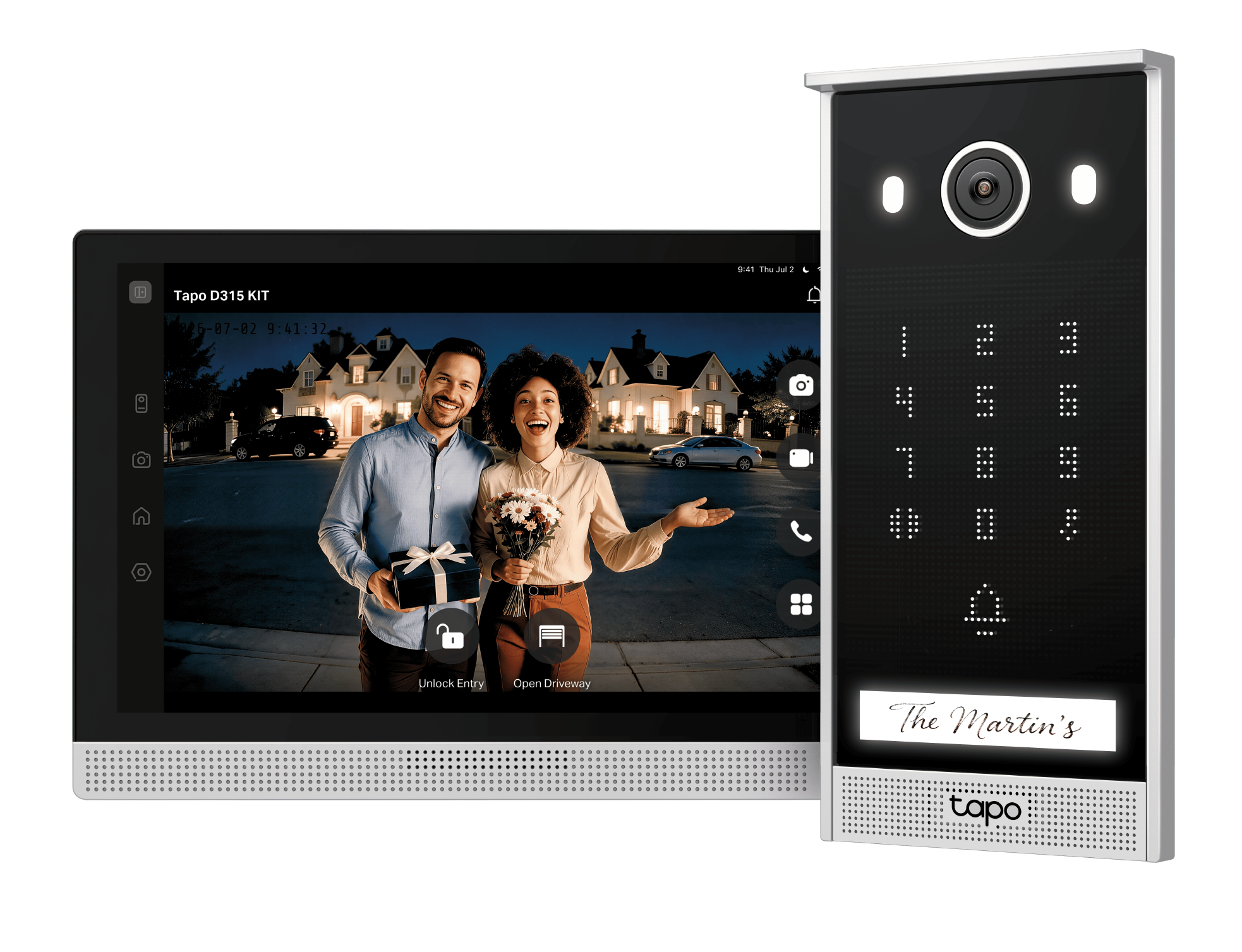
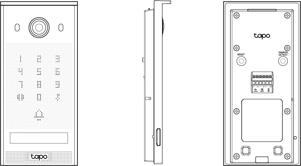
Step 1. Know about your intercom panel
In this section, we will describe the appearance of the intercom panel, including its ports, buttons, and labels.
1. First, place your intercom panel on a horizontal surface, such as on a shelf or desktop. Position it with the lens facing up and on the upper side.
2. After positioning your intercom panel correctly, we will introduce the ports, buttons, and labels on your device in a certain order.
Lens: For capturing objects within its view.
White LEDs: There are two White LEDs positioned on the left and right sides of the lens.
On the touch keypad:
0-9 Number Buttons: Enter the PIN code set in the app and then tap the Unlock or Open Gate button for access.
NFC Reading Zone: The area circling 4-9 number buttons is the NFC recognition area. Swipe the NFC card here and then tap the Unlock or Open Gate button for access. You can add or delete NFC cards in the app.
Open Gate Button: Positioned on the left of the 0 button.
Unlock Button: Positioned on the right of the 0 button.
Ring Button: For ringing the doorbell. Positioned below the 0 button.
Name Holder: For inserting the name card.
Speaker: The holes located down below.
Turn to the left side panel to find the microphone.
microSD Card Slot: Insert a microSD card (not included) with the notch facing right.
Turn to the back panel to find the following buttons from top to bottom and left to right.
RESET Button: While the intercom panel is powered on, press and hold the RESET button for 10 seconds to reset the device.
Tamper Detect Button: When the Anti-Theft Alarm is enabled on the Tapo app, an alarm will trigger once the intercom panel is removed. Pressing and holding the Tamper Detect button for 5seconds will pause the alarm (Continues to alarm when released). Pressing and holding the RESET button and Tamper Detect button simultaneously for 10 seconds will disable the anti-theft alarm feature.
Wiring Terminals: There are six terminals. The first two are Lock terminals for connecting the wires that unlock the pedestrian gate. The middle two terminals are GATE terminals for connecting the wires that open the driveway gate. The last two are DB terminals for connecting the intercom panel to the screen to provide power supply and network to the intercom panel.
Product label: The product label is on the back of the intercom panel.
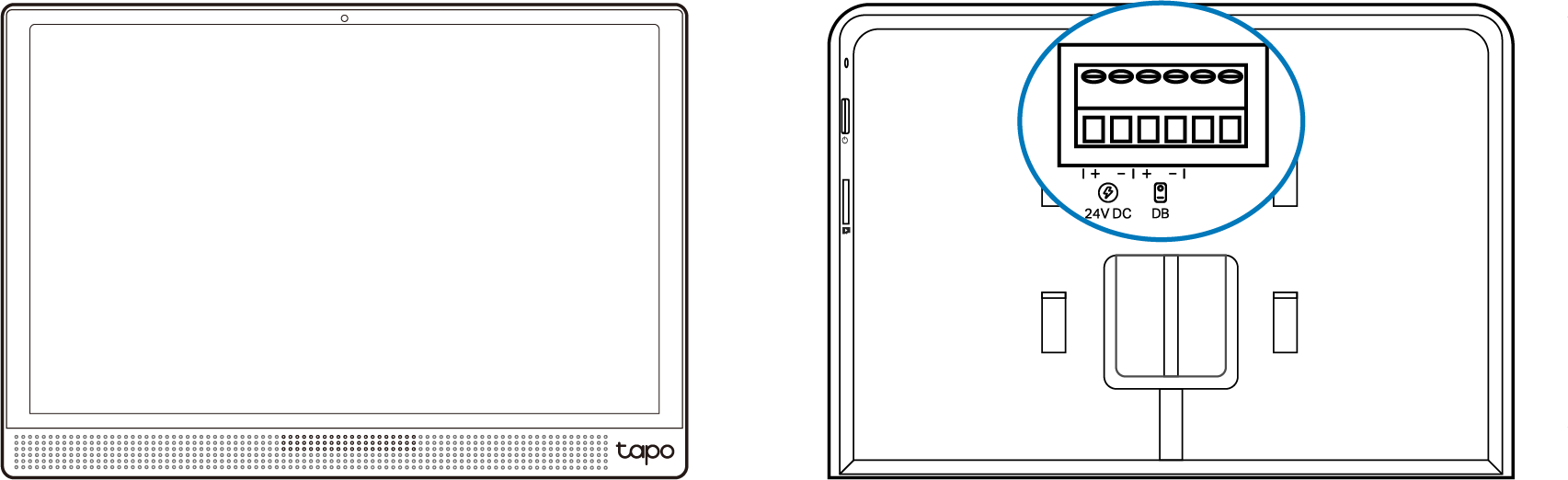
Step 2. Know about your smart screen
In this section, we will describe the appearance of the smart screen, including its ports, buttons, and labels.
1. You can find your screen and the power adapter in the package.
Power Adapter: A block with a power cord at the end. Connect it to a power outlet to power your device.
2. Next, place your screen on a horizontal surface, such as on a shelf or desktop. Position it with the screen facing up and the speaker holes on the bottom.
3. After positioning your screen correctly, we will introduce the ports, buttons, and labels on your device in a certain order.
Light Sensor: It is on the top middle part.
Speaker: The holes located down below.
On the right side panel, you can find the following buttons from top to bottom.
Microphone: For capturing your voice.
On/Off Button:
• Press once: Turn on/off the screen display. If the device is in a call, the call will be ended.
• Press and hold for 5 seconds: Restart the device.
• Press and hold for 10 seconds: Factory reset the device.
microSD Card Slot: Insert a microSD card (not included) up to 512 GB and initialize it on the Tapo app for local recording and screenshots.
Turn to the back panel to find the following buttons from top to bottom.
Wiring Terminals: There are six terminals. The first two are 24V DC terminals for connecting to a 24V DC (at least 1.5A) power supply. The middle two terminals are DB terminals for connecting the intercom panel to the screen to provide power supply and network to the intercom panel. Leave the last terminals unused.
DC Power Port: Plug in the power adapter to power your device.
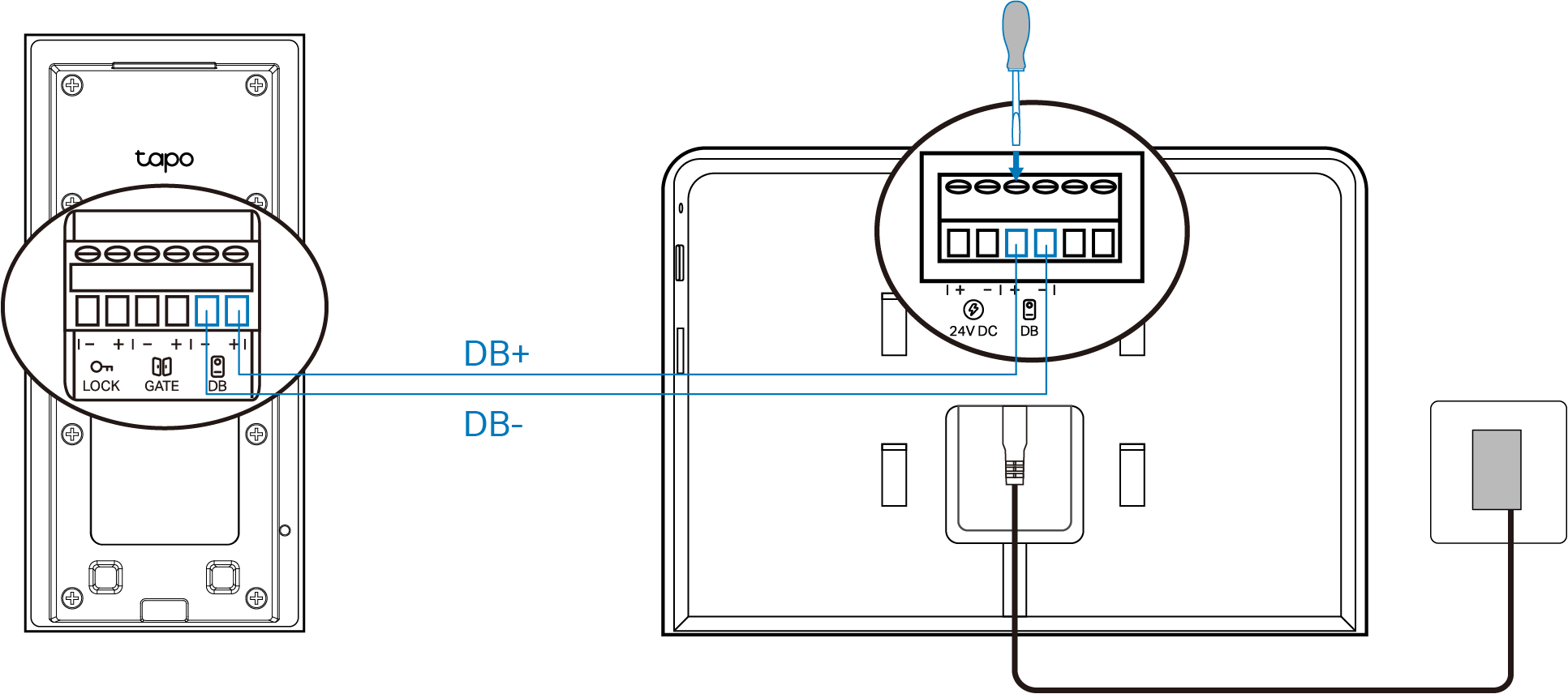
Step 3. Test and Set Up
1. Wire the Intercom Panel to the Screen for Testing
Loosen the fixing screws for the DB terminals by turning counterclockwise with the provided screwdriver. Use two provided wires to connect the intercom panel to the screen, and tighten the screws. Plug in the power adapter.
2. Download the App
Get the Tapo app from the App Store or Google Play, then log in.

2. Tap the + button in the app and select your device model. Follow the instructions on the Tapo app to set up your doorbell.
3. Set Up
Tap the + button in the Tapo app, select Scan QR Code, and then scan the displayed code on the screen. Follow the app instructions to set up the kit to make sure it works.
Step 4. Installation
Follow app instructions or check the user manual to install your intercom panel and screen.
If you need help, please visit https://www.tapo.com/support/ for technical support, the user guide, FAQs, warranty & more.
For details on Tapo app accessibility, please check Accessibility Support.
Safety Information
For the Smart Screen:
• Keep the device away from water, fire, humidity, or hot environments.
• Do not attempt to disassemble, repair, or modify the device. If you need service, please contact us.
• Do not use any other chargers than those recommended.
• Do not use the device where wireless devices are not allowed.
• Do not use a damaged charger or USB cable to charge the device.
• Adapter shall be installed near the equipment and shall be easily accessible.
• Use only the power supplies listed in the user instructions. Refer to the User Manual on the product support page. Do not use any other power supplies than those recommended.
• An all-pole disconnect device in accordance with IEC 62368-1 Annex L shall be incorporated in the electrical installation of the building.
• The product shall not be directly connected to primary power and shall derive its power from a safety isolating transformer whose secondary circuit is double/reinforced insulated from the mains or derive its power from batteries.
• The mounting height should not be higher than 2 meters.
• Screen Operating Temperature: -10 ℃~45 ℃ (14 °F ~ 113 °F)
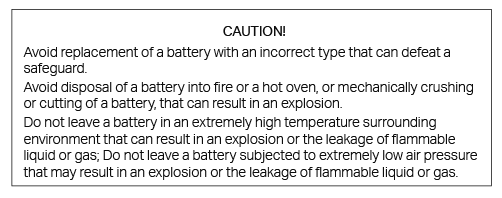
For the Intercom Panel:
• Keep the device away from fire or hot environments. DO NOT immerse in water or any other liquid.
• Do not attempt to disassemble, repair, or modify the device. If you need service, please contact us.
• Do not use the device where wireless devices are not allowed.
• The mounting height should not be higher than 2 meters.
• The intercom panel can only be powered by the screen.
• Intercom Panel Operating Temperature: -30 ℃ ~ 55 ℃ (-22 °F ~ 131 °F)
Please read and follow the above safety information when operating the device. We cannot guarantee that no accidents or damage will occur due to improper use of the device. Please use this product with care and operate at your own risk.
For the Smart Screen:
TP-Link hereby declares that Smart Screen is in compliance with the essential requirements and other relevant provisions of directives 2014/53/EU, 2009/125/EC, 2011/65/EU and (EU) 2015/863.
The original EU declaration of conformity may be found at https://www.tapo.com/support/ce/
TP-Link hereby declares that Smart Screen is in compliance with the essential requirements and other relevant provisions of the Radio Equipment Regulations 2017.
The original UK declaration of conformity may be found at https://www.tapo.com/support/ukca/
For the Intercom Panel:
TP-Link hereby declares that Smart Intercom is in compliance with the essential requirements and other relevant provisions of directives 2014/53/EU, 2011/65/EU and (EU) 2015/863.
The original EU declaration of conformity may be found at https://www.tapo.com/support/ce/
TP-Link hereby declares that Smart Intercom is in compliance with the essential requirements and other relevant provisions of the Radio Equipment Regulations 2017.
The original UK declaration of conformity may be found at https://www.tapo.com/support/ukca/