How to integrate POS devices with VIGI NVR
POS Devices Integration with VIGI NVR
Scenario 2: RS-232 POS (Serial Port) + NVR
Configure POS Settings on the VIGI NVR GUI
View and Search POS Information
View POS Information in Live View
View and Search POS Event in Playback
Search from Search > Event > POS Event
Introduction
In commercial checkout scenarios such as retail stores, restaurants, and other transaction-based environments, VIGI NVR supports the POS function to link transaction data with video surveillance. When an IPC monitors the cashier area and a POS device performs a payment or transaction operation, the NVR can receive data from the specified POS device and parse the corresponding transaction text. The parsed POS information can be overlaid on the Live View screen in real time, helping operators view the on-site video associated with a specific order. After receiving POS messages, the NVR can also trigger linkage actions such as Record Linkage, Pop-up Alarm Screen, Push Notifications, Send Email, Highlight Window, and Alarm Output. Operators can also search for POS-related information in the Search module, allowing them to quickly locate abnormal transactions and the corresponding video clips.
Requirements
- A VIGI NVR that supports the POS function.
- VIGI cameras or third-party cameras added to the NVR.
- A POS Server, POS terminal, or POS system that can output transaction text data.
- If TCP or UDP output is supported, the Pos data can be sent directly to the NVR’s IP address and POS listening port.
- If only RS232 output is supported, an RS232-to-IP converter is required.
POS Devices Integration with VIGI NVR
Introduction
There are two common methods for integrating a POS system with the VIGI NVR: network connection and serial port connection. For network integration, the POS Server, POS terminal, or POS system sends transaction text data directly to the NVR’s IP address and POS listening port via TCP or UDP. For serial port integration, when the POS system only provides RS232 output, an RS232-to-IP converter is required to convert the serial data into network data before forwarding it to the NVR.
Scenario 1: Network POS + NVR
In this scenario, the POS terminal or POS system sends transaction text data to the VIGI NVR over the IP network. The NVR receives the POS data through the configured POS listening port and links the transaction information with the corresponding video channel. The connection topology is shown below.
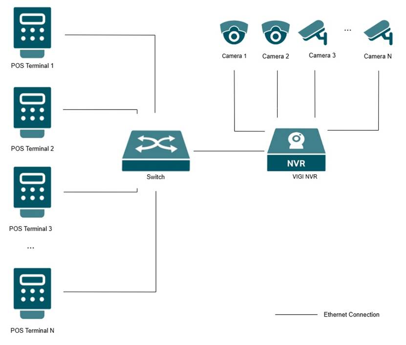
Network Connectivity: Ensure that the POS terminal or POS system can reach the VIGI NVR’s IP address and POS listening port over the network.
Scenario 2: RS-232 POS (Serial Port) + NVR
In this scenario, the POS terminal outputs transaction text data through its RS232 serial port. The RS232-to-IP converter receives the serial data from the POS terminal, converts it into network data, and forwards it to the VIGI NVR. The connection topology is shown below.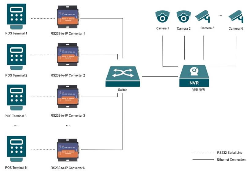
Connection Method:
Connect the RS232 output of the POS terminal to the RS232-to-IP converter. Then connect the converter and the VIGI NVR to the network so that the converter can forward POS data to the NVR’s IP address and POS listening port.
Serial Parameter Matching:
When RS232 output is used, confirm the serial communication parameters from the POS terminal or POS vendor, including baud rate, data bits, parity, and stop bits. Configure the RS232-to-IP converter with the same serial parameters so that it can correctly receive the transaction text data from the POS terminal.
Note: The USR-TCP232-302 converter has been tested and verified for this integration scenario. If another RS232-to-IP converter is used, please test and confirm its compatibility before deployment.
The following converter settings use the USR-TCP232-302 as an example. For other RS232-to-IP converters, the parameter names and available options may vary. Please refer to the corresponding converter manual.
Converter Settings Example
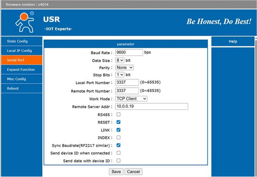
- Local IP Configuration: Assign a static IP address to the converter to prevent connection issues caused by IP address changes.
- Serial Port Settings:
Configure the converter’s serial port parameters to match the POS terminal’s RS232 output settings.
|
Parameter |
Example Value |
Description |
|
Baud Rate |
9600 |
Must match the POS RS232 output setting. |
|
Data Size |
8 bit |
Must match the POS RS232 output setting. |
|
Parity |
None |
Must match the POS RS232 output setting. |
|
Stop Bits |
1 bit |
Must match the POS RS232 output setting. |
Configure the converter to forward the received RS232 data to the VIGI NVR over the network.
|
Parameter |
Example Value |
Description |
|
Work Mode |
TCP Client |
The converter actively connects to the NVR. |
|
Remote Server Address |
NVR IP Address |
Enter the IP address of the VIGI NVR. |
|
Remote Port Number |
NVR POS Listening Port |
Must match the port configured in the NVR POS TCP Connection Settings. |
|
Local Port Number |
Same as the NVR POS Listening Port, or as required by the converter |
Used by the converter locally. Follow the converter manual if different. |
- Other Options
In the tested USR-TCP232-302 configuration, RESET, LINK, and Sync Baud Rate are enabled. Other vendor-specific options can remain disabled unless otherwise required by the converter vendor.
Configuration
Configure POS Settings on the VIGI NVR GUI
Step 1. Connect a monitor and a mouse to the VIGI NVR. On the Live View screen, right-click and select System from the pop-up menu. If you have not logged in before, enter the NVR username and password to log in.
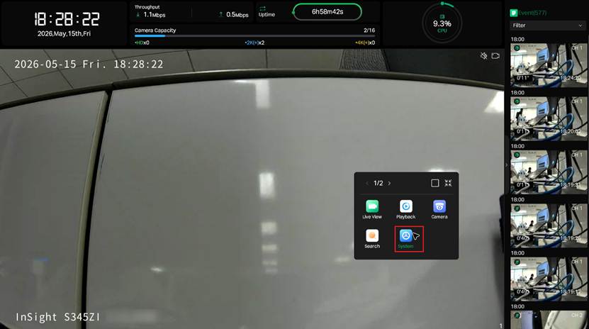
Step 2. Navigate to System > POS.
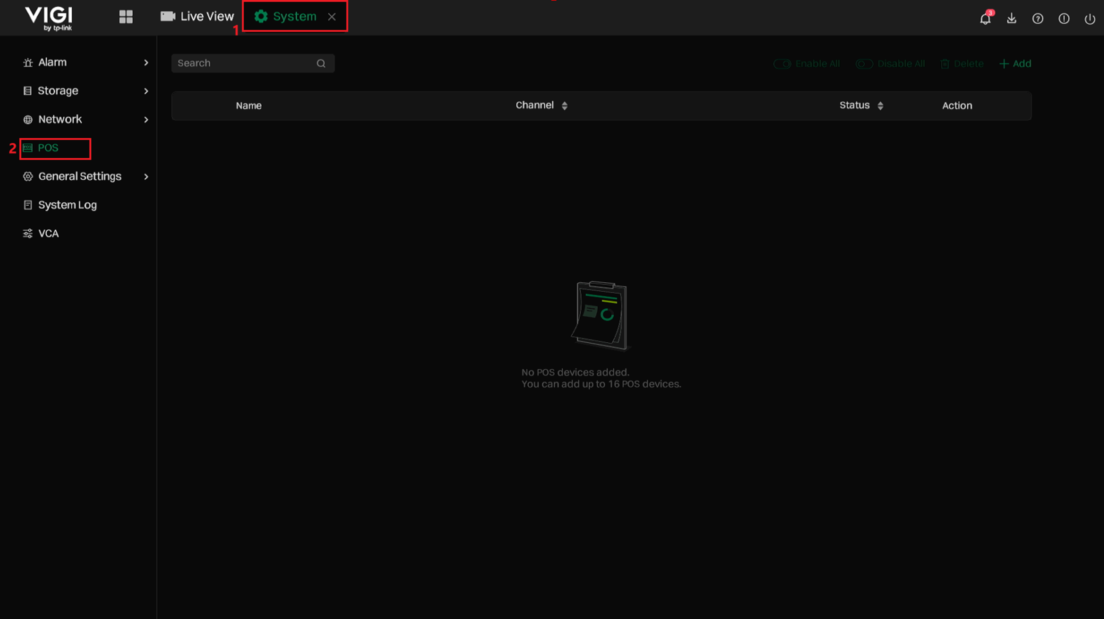
Step 3. Click Add to add a POS entry and then configure the POS parameters according to the actual POS integration scenario.
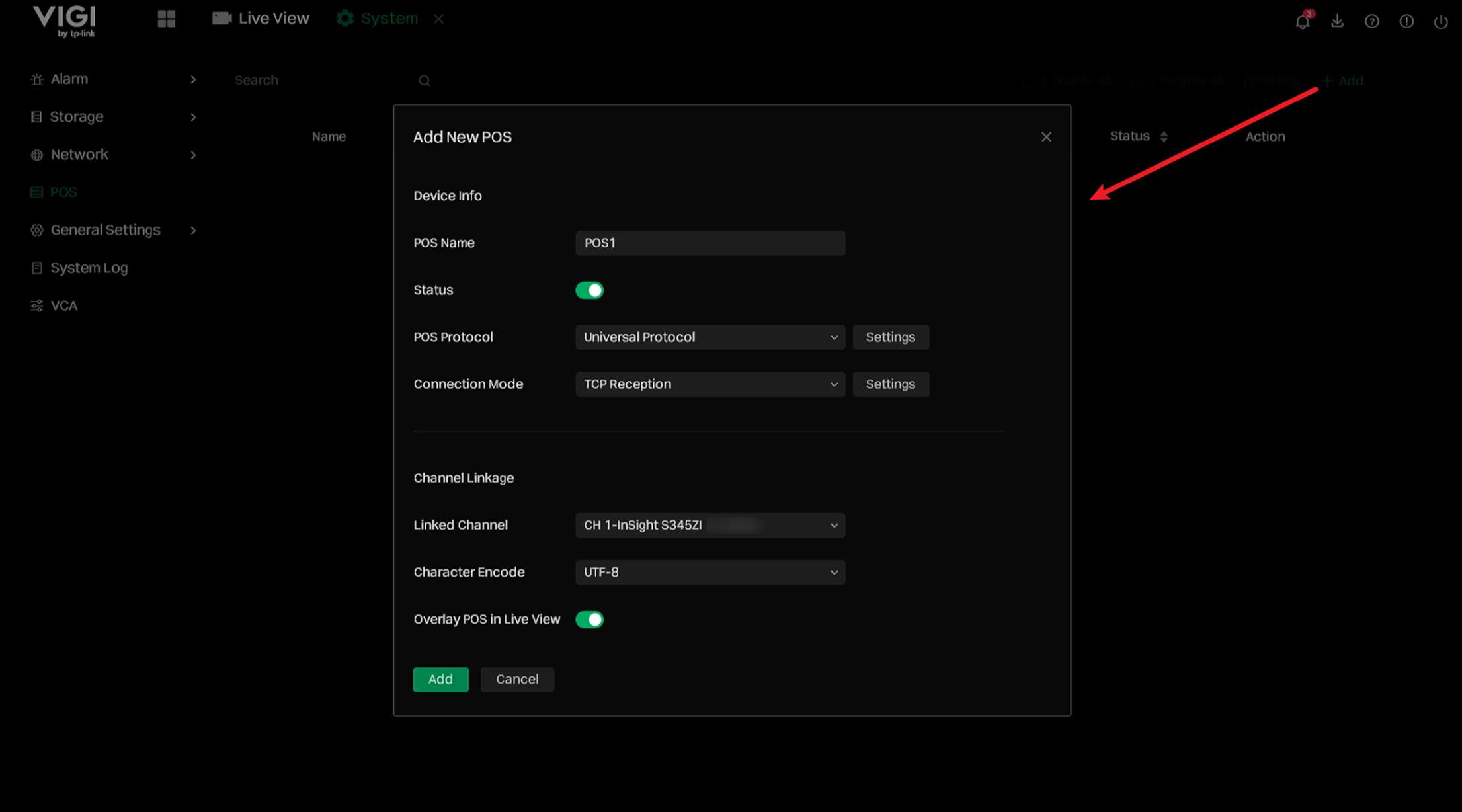
- POS Name: Specifies the name of the POS entry.
- Status: Enables or disables the POS entry. When enabled, the NVR can receive POS data for this entry.
- POS Protocol: By default, Universal Protocol is used.
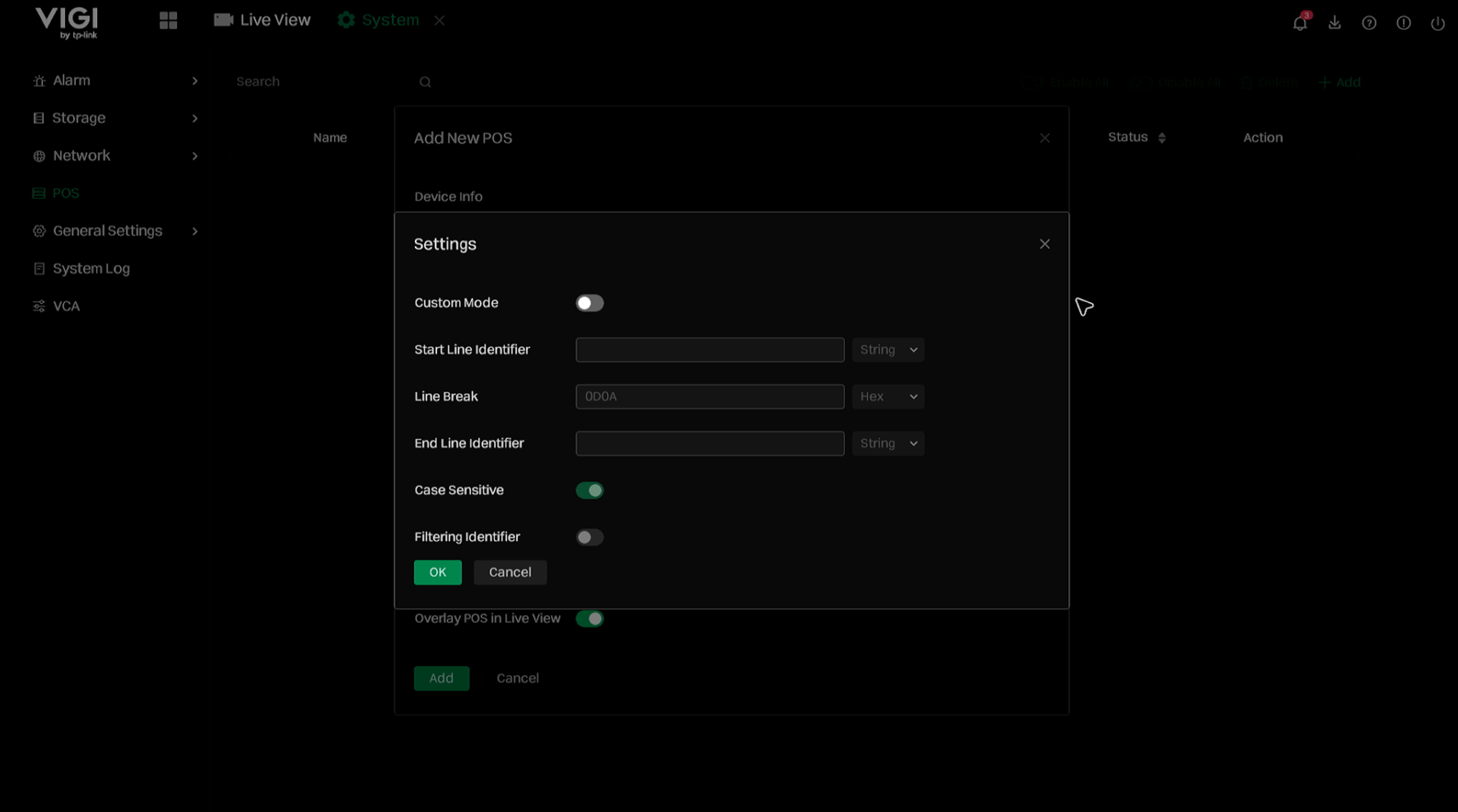
In the Universal Protocol configuration, Custom Mode is disabled, Start Line Identifier and End Line Identifier are empty, Line Break is set to 0D0A in Hex format (\r\n), Case Sensitive is enabled, and Filtering Identifier is disabled. If the POS terminal uses a specific receipt format, or if you want the NVR to identify a complete receipt as one POS event, click Settings to configure the parsing rules.
The following table describes the parameters available in the Pos Protocol settings.
|
Parameter |
Description |
|
Custom Mode |
Enables custom parsing rules for POS data. When enabled, the NVR parses POS data according to the configured Start Line Identifier, Line Break, and End Line Identifier. |
|
Start Line Identifier |
Defines the string that indicates the start of a POS event or receipt. When the NVR receives this string, it treats the following POS data as the beginning of a POS event. |
|
Line Break |
Defines the line break format used to separate POS text into different lines. The default value is 0D0A in Hex format, which represents \r\n. |
|
End Line Identifier |
Defines the string that indicates the end of a POS event or receipt. When the NVR receives this string, it treats the current POS event as completed. |
|
Case Sensitive |
Determines whether identifier matching is case-sensitive. When enabled, uppercase and lowercase letters are treated as different characters. |
|
Filtering Identifier |
Determines whether the configured Start Line Identifier and End Line Identifier are displayed in the POS overlay. When enabled, these identifiers are used for parsing but are not displayed in the POS text. |
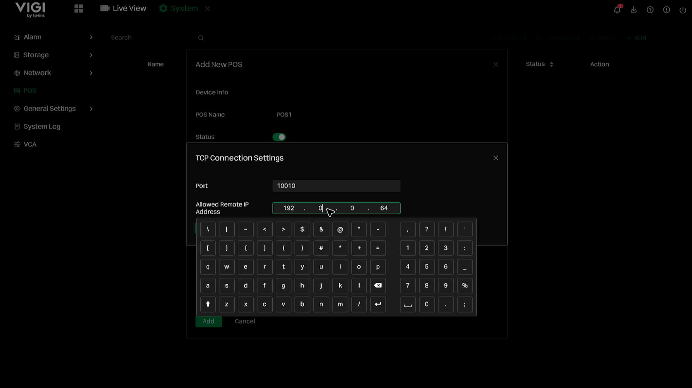
- Connection Mode: Specifies how the NVR receives POS data. TCP and UDP are supported. Click Settings to configure the POS listening port and the allowed source IP address.
Parameter
Description
Port
The port opened by the NVR to listen for POS data.
Allowed Remote IP Address
The source IP address from which the NVR is allowed to receive POS data.
- Linked Channel : Selects the camera channel associated with this POS entry. The received POS transaction data will be linked to the selected channel for live view overlay, playback, and POS event search.
- Character Encode: Specifies the character encoding used to display POS text. Currently, only UTF-8 is supported.
- Overlay POS in Live View: Enables or disables POS text overlay on the Live View screen. When enabled, the parsed POS transaction information will be displayed on the linked channel in real time.
Step 4. After completing the configuration, click Add to add the POS entry.
Step 5. Configure Area Parameters, Alarm Schedule, and Triggered Action according to the actual display and event linkage requirements.
- Area Parameters: After the POS entry is created, configure Area Parameters to define how the POS information is displayed and handled on the linked video channel
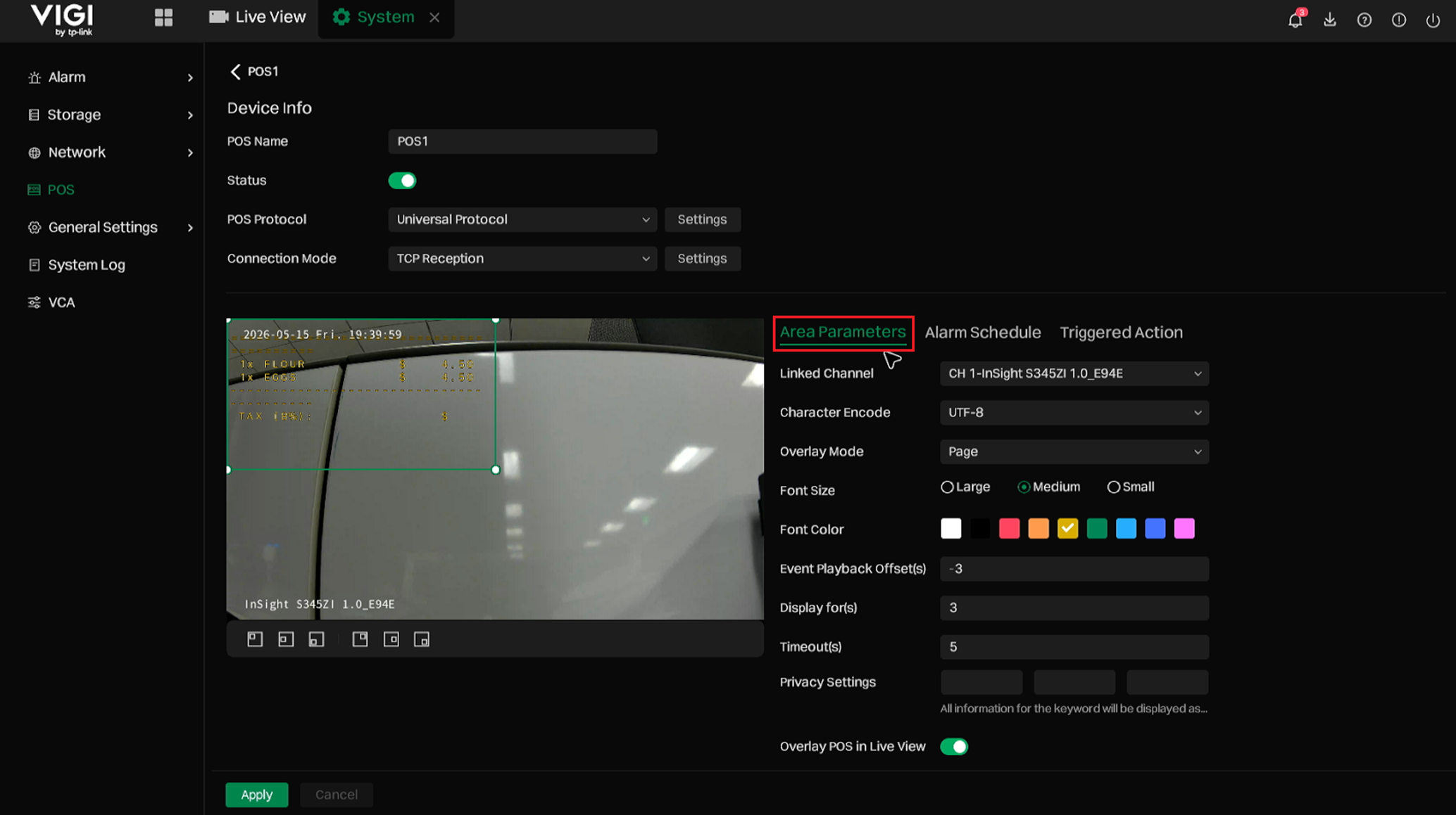
The following table describes the options available in Area Parameters.
|
Parameter |
Description |
|
Display Area |
Defines the position and size of the POS text overlay on the video image. Adjust the display area according to the actual video layout. |
|
Overlay Mode |
Specifies how POS text is displayed on the video, such as page display or scrolling display. |
|
Font Size |
Specifies the font size of the POS text overlay. |
|
Font Color |
Specifies the font color of the POS text overlay. Select a color that is clearly visible on the video image. |
|
Event Playback Offset(s) |
Specifies how many seconds before the POS event the playback should start when reviewing the event. |
|
Display for(s) |
Specifies how long the POS information remains displayed on the video when no new POS data is received. |
|
Timeout(s) |
Specifies the timeout period used to determine the end of a POS event when no new POS data is received. |
|
Privacy Settings |
Masks sensitive information in POS text based on configured keywords. This can be used to hide information such as card numbers, phone numbers, or customer information. |
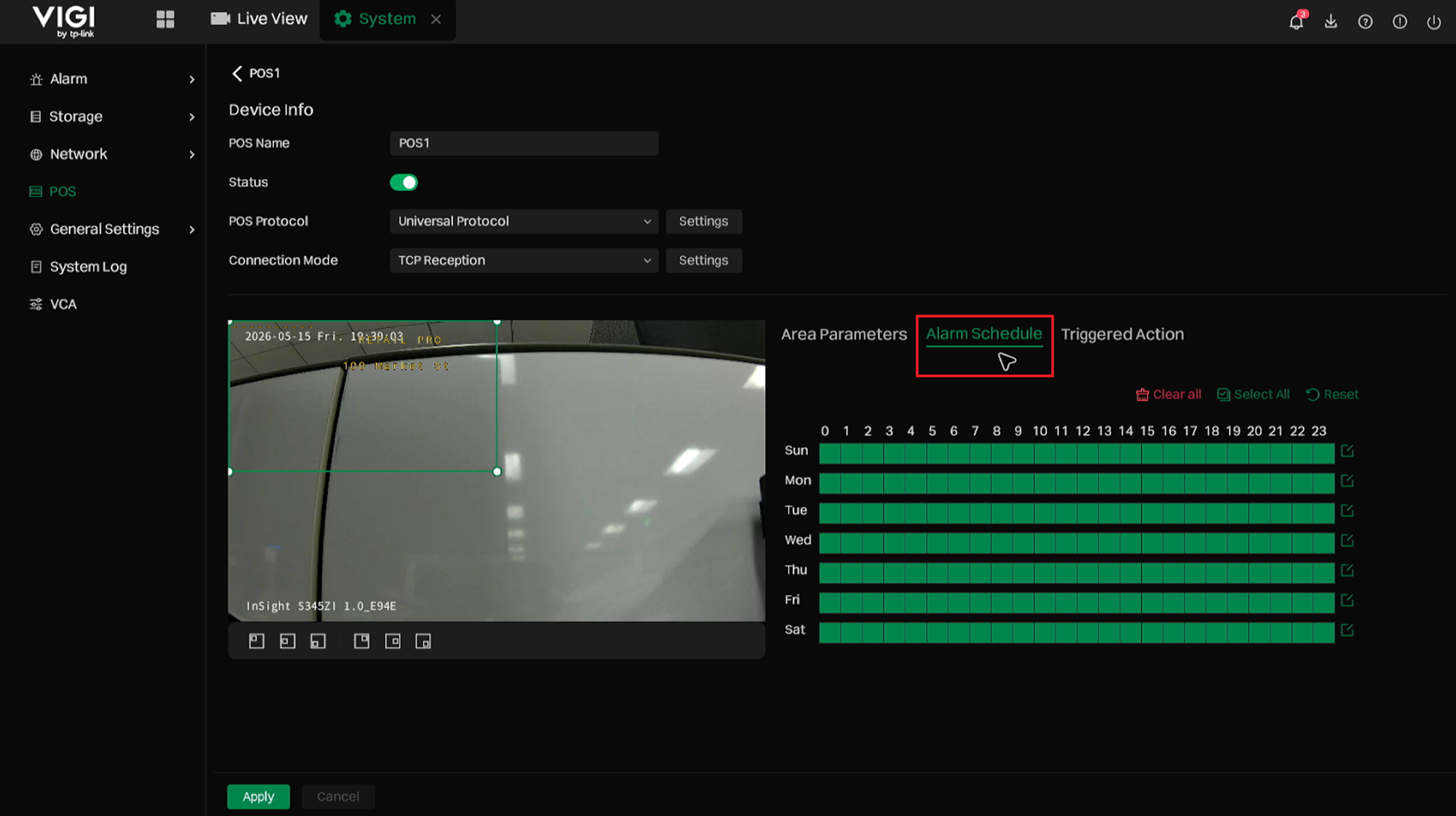
- Alarm Schedule: Configure Alarm Schedule to define when the POS event rule is active.
- Triggered Action: Configure Triggered Action to define the actions that will be triggered after the NVR receives POS data and generates a POS event.
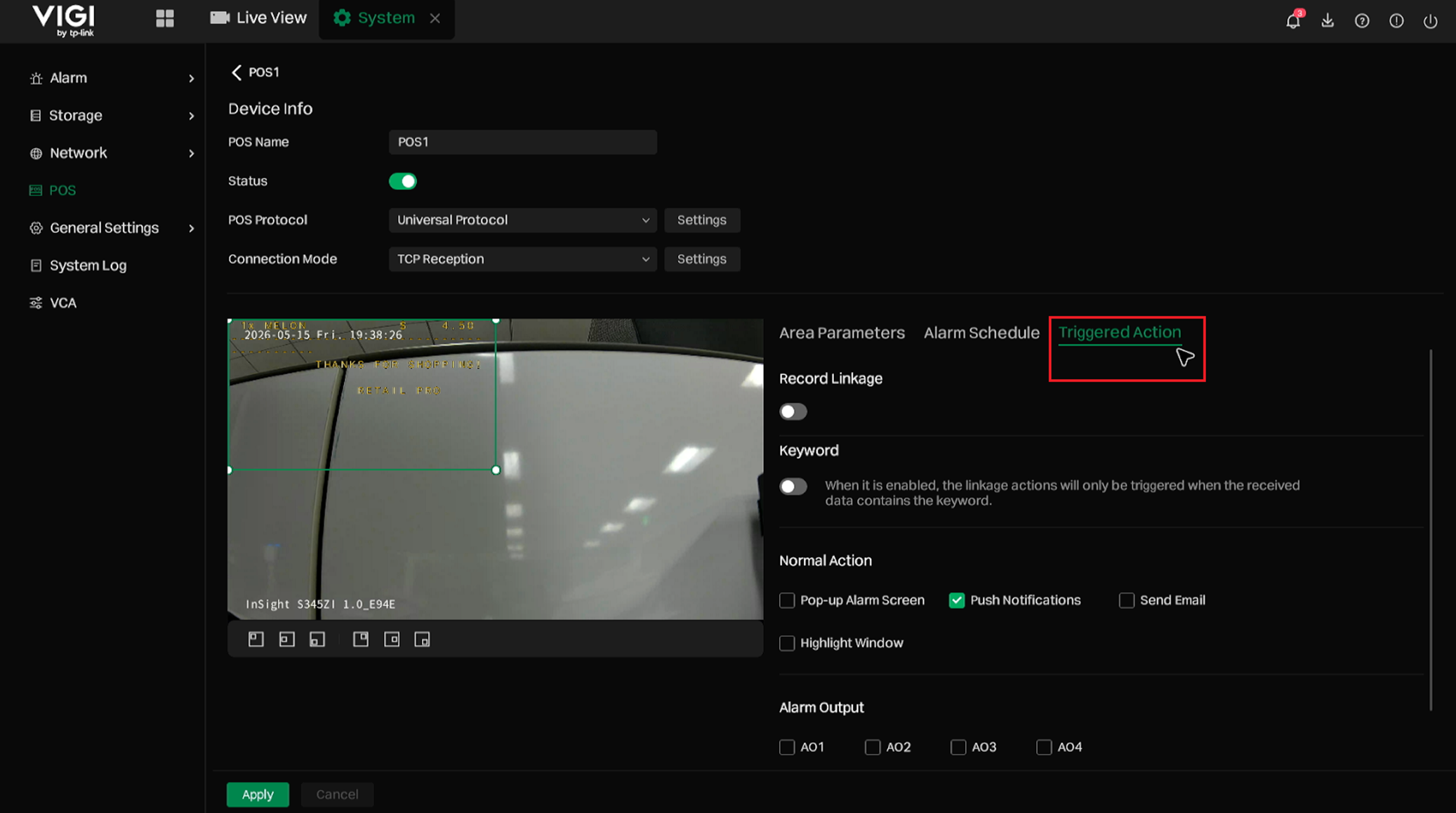
The following table describes the options available in Triggered Action.
|
Parameter |
Description |
|
Record Linkage |
Triggers recording on selected channels when a POS event occurs. |
|
Keyword |
When enabled, Normal Action and Alarm Output will only be triggered when the received POS data contains the configured keyword. |
|
Normal Action |
Includes linkage actions such as Pop-up Alarm Screen, Push Notifications, Send Email, and Highlight Window. |
|
Alarm Output |
Triggers the NVR Alarm Output or Channel Alarm Output when the POS event meets the configured conditions. |
Step 6. Click Apply to save the configuration.
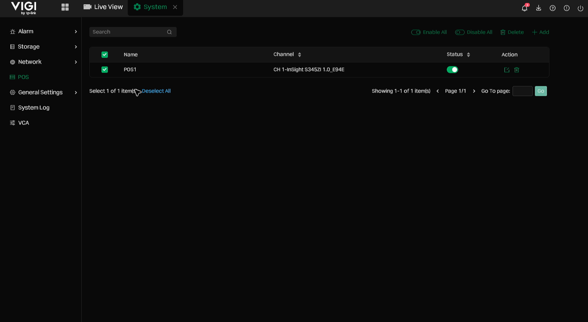
Step 7. (Optional) After POS entries are created, they will be displayed in the POS list. In this list, the POS name, linked channel, status, and available actions can be viewed. One or multiple POS entries can also be selected to enable, disable, or delete them in batches.
View and Search POS Information
View POS Information in Live View
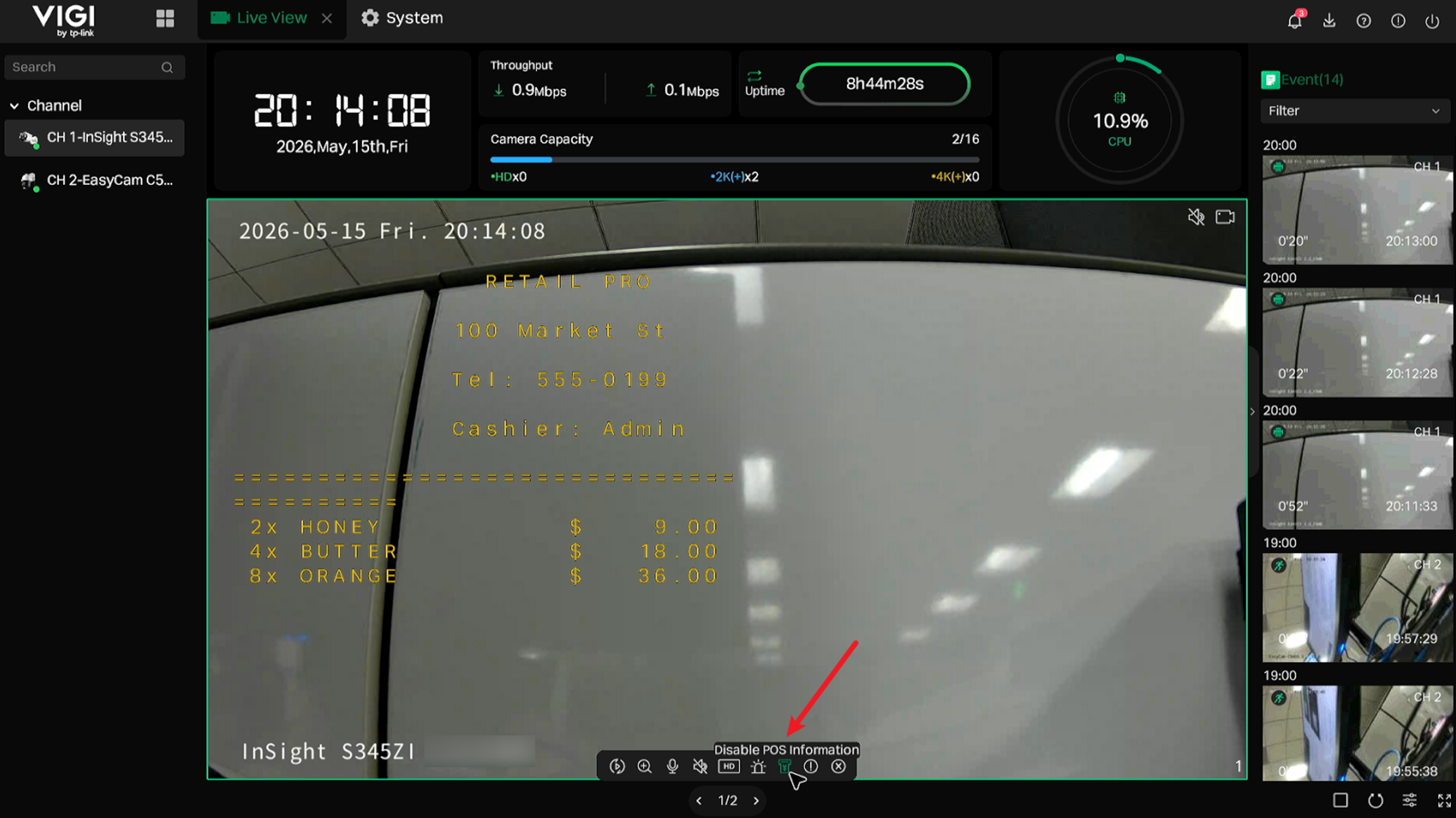
The POS information displayed in Live View can be enabled or disabled using the switch on the toolbar. When enabled, the parsed POS transaction text will be overlaid on the linked channel in real time, allowing operators to view the transaction information together with the on-site video.
Note: This switch corresponds to the Overlay POS in Live View option on the POS Settings page.
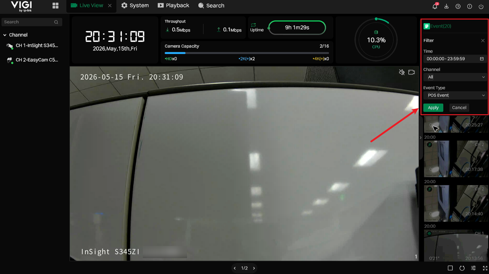
Open the Event panel on the right side. Set the filter conditions, select POS Event as the Event Type, and click Apply. The POS events will be displayed in the event list for quick review.
View and Search POS Event in Playback
On the Playback page, POS information can be displayed or hidden by using the POS information switch in the toolbar. This setting takes effect on the currently selected channel, allowing operators to review transaction text together with the corresponding video footage.
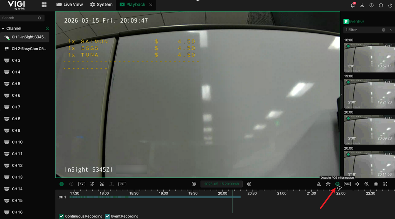
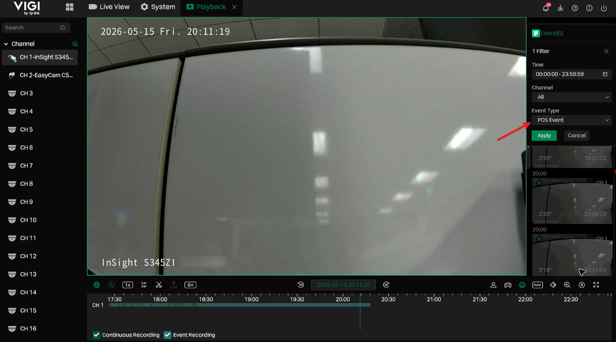
Select the POS event type in the right sidebar to search for POS events of the current day.
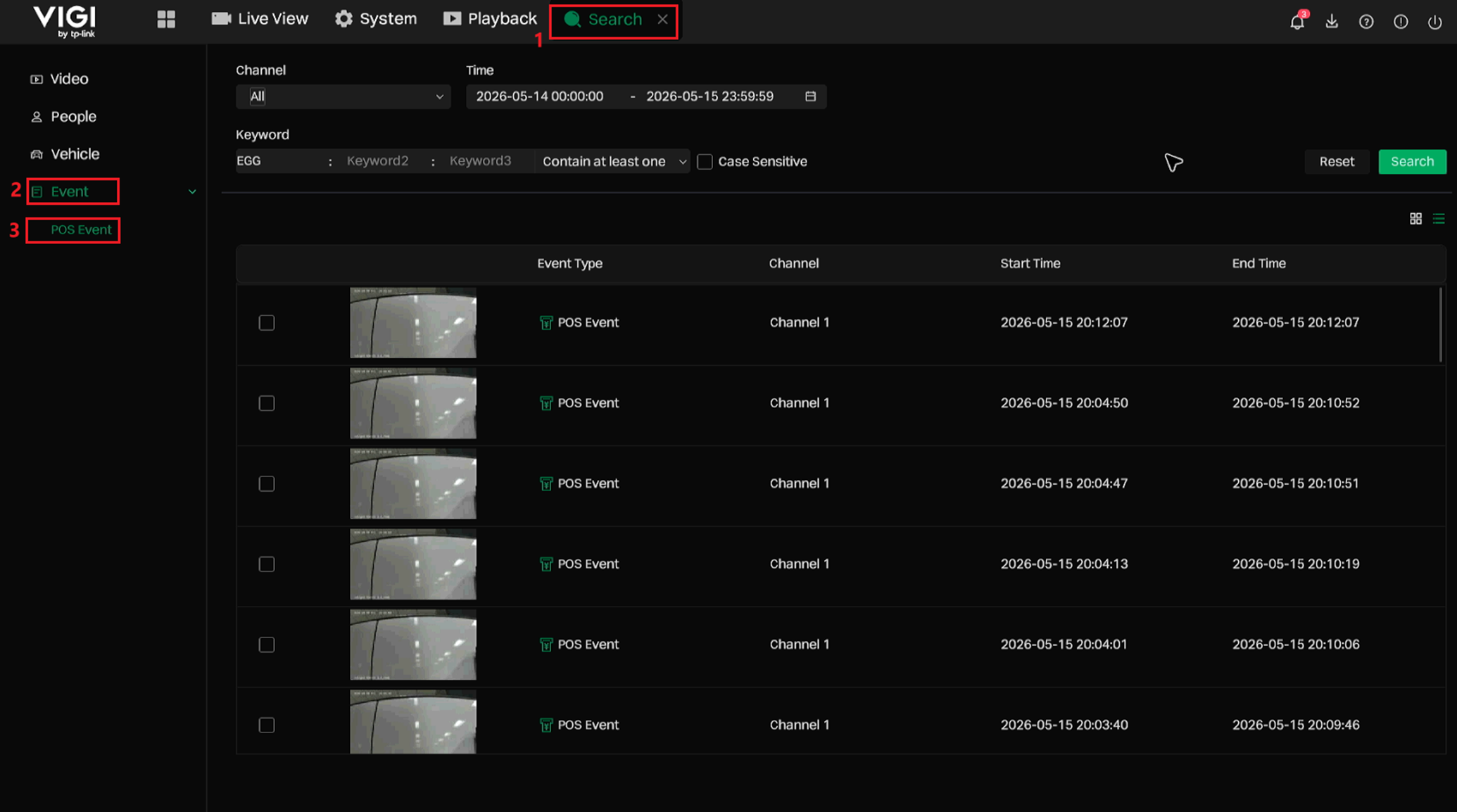
Search from Search > Event > POS Event
Navigate to Search > Event > POS Event. POS events can be searched by channel, time, and keyword, helping operators locate transaction-related video clips more efficiently.
Conclusion
Based on the configurations above, POS integration can be implemented on the VIGI NVR to display and search for POS transaction information with the corresponding video.
QA
Q1: What should I do if the NVR cannot receive POS data?
A1: Please check the following items:
- Confirm that the POS entry is enabled on the NVR.
- Confirm that the POS terminal, POS system, or RS232-to-IP converter can reach the NVR’s IP address and POS listening port over the network.
- Confirm that the Connection Mode on the NVR is correctly configured as TCP or UDP according to the POS data output method.
- Confirm that the Port configured on the NVR is the same as the destination port configured on the POS system or RS232-to-IP converter.
- Confirm that the Allowed Remote IP Address on the NVR is set to the actual source IP address of the POS system or converter.
- If RS232 is used, confirm that the converter is receiving serial data from the POS terminal and forwarding it to the NVR over the network.
Q2: What should I do if the NVR can establish a connection but no POS text is displayed?
A2: Please check the following items:
- Confirm that the POS system is actually sending transaction text data, not only establishing a TCP/UDP connection.
- Confirm that Overlay POS in Live View is enabled.
- Confirm that the correct Linked Channel is selected for the POS entry.
- Confirm that the POS display area is within the video image and not outside the visible area.
- Confirm that the POS data format can be parsed by the selected POS protocol.
- If Custom Mode is enabled, confirm that the Start Line Identifier, Line Break, and End Line Identifier match the actual POS output.
Q3. What should I do if the POS text is garbled or displayed incorrectly?
A3: This is usually related to character encoding or serial parameter mismatch.
Please check the following items:
- Confirm that the POS transaction text is encoded in UTF-8, since the current Character Encode option supports UTF-8.
- If RS232 is used, confirm that the POS terminal and RS232-to-IP converter use the same serial parameters:
- Baud rate
- Data bits
- Parity
- Stop bits
- If the serial parameters do not match, the converter may receive garbled data and forward abnormal text to the NVR.
Q4. What should I do if POS data is split into multiple events unexpectedly?
A4: This may happen when the NVR cannot identify the start and end of a complete receipt.
Please check the following items:
- If the POS receipt has a fixed start line and end line, enable Custom Mode.
- Configure Start Line Identifier based on the fixed text at the beginning of the receipt.
- Configure End Line Identifier based on the fixed text at the end of the receipt.
- Confirm that Line Break matches the actual POS output format. The default 0D0A represents \r\n.
Q5. What should I do if the Start Line Identifier or End Line Identifier is not matched?
A5: Please check the following items:
- Confirm that the identifier text is exactly the same as the POS output.
- If Case Sensitive is enabled, uppercase and lowercase letters must match exactly.
- Confirm whether there are extra spaces, symbols, or punctuation in the POS output.
- If the identifier includes punctuation, such as THANKS FOR SHOPPING!, include the full string for testing.
Q6. What does Filtering Identifier do?
A6: Filtering Identifier controls whether the configured Start Line Identifier and End Line Identifier are displayed in the POS overlay.
- When enabled, the identifiers are used for parsing but are not displayed in the POS text.
- When disabled, the identifiers are displayed as part of the POS information.
Q7. What should I do if the RS232-to-IP converter is used but the NVR still cannot receive POS data?
A7: Please check the following items:
- Confirm that the POS RS232 output is connected to the converter correctly.
- Confirm that the converter’s serial parameters match the POS terminal’s RS232 output parameters.
- Confirm whether the converter's IP address has changed.
- Confirm that the converter is configured to forward data to the NVR’s IP address and POS listening port.
- If TCP is used, the converter is recommended to work in TCP Client mode, and the NVR should be configured with TCP Reception.
- Confirm that the NVR’s Allowed Remote IP Address is set to the converter’s IP address.
Q8. What should I do if linkage actions are not triggered after receiving POS data?
A8: Please check the following items:
- Confirm that the POS event is generated successfully.
- Confirm that Alarm Schedule covers the current time.
- Confirm that the required actions are enabled under Triggered Action.
- If Keyword is enabled, Normal Action and Alarm Output will only be triggered when the received POS data contains the configured keyword.
- Confirm that the configured keyword matches the actual POS text.
Get to know more details of each function and configuration please go to Download Center to download the manual of your product.
Looking For More
Is this faq useful?
Your feedback helps improve this site.


TP-Link Community
Still need help? Search for answers, ask questions, and get help from TP-Link experts and other users around the world.