


How to use CPEs to build up a LAG (Link Aggregation) tunnel
User’s Application Scenario
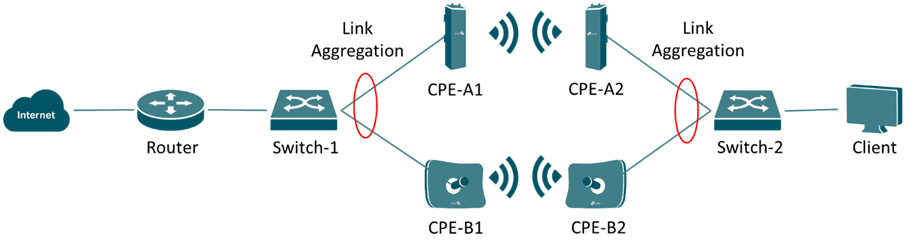
With the LAG (Link Aggregation Group) function, you can aggregate multiple physical ports into a logical interface. Typical LAG setups use Ethernet cables as physical tunnels. In practice, you can also use CPEs to build point-to-point links as LAG tunnels, just as the topology shown as follows.
Configuration
Step 1. Config CPEs.
In this step, you will set up the four CPEs to establish two point-to-point wireless links. For each pair of CPEs, one should be set to Access Point and another in Client mode. For example, set CPE-A1 to AP mode and CPE-A2 to Client mode. The same thing for CPE-B1 and CPE-B2.
For CPE setup (pairing) instructions, refer to: quick_start_guide_cpe_and_wbs_ (tp-link.com).
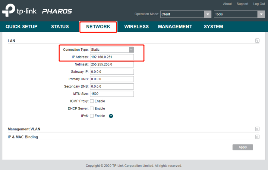
(Optional) You can set different static IPs for each of your CPEs for management convenience. Go to CPE’s Web UI -->Network -->LAN Settings -->IP Address to set it manually. However, leaving them to default value (192.168.0.254) is also OK.
Note: Do NOT connect both CPEs to switches BEFORE setting up LAG (Step 2) to avoid loop problem.
Step 2. Set Static LAG on switches.
There are two modes of LAG: Static LAG and Dynamic LAG (LACP). In this case, we should use Static LAG because LACP mode may cause a broadcast storm in this scenario.
Create a Static LAG group of two ports on both Switch-1 and Switch-2.LAG setup instructions:
For easy smart switches, go to the switch’s Web UI -->Switching -->LAG.
For Smart/Managed switches, refer to: configuring_lag (tp-link.com).
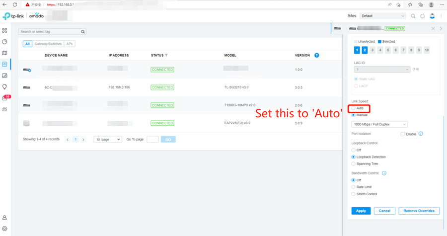
For Omada Controller managed devices, refer to: Omada SDN Controller User Guide | TP-Link Chapter 6.3.1 – Configure Switches – Configure a LAG.
Note: While using Omada Controller to set LAG on switches for CPEs to connect, please make sure that the Link Speed is at ‘Auto’ mode.
Unmanaged switches do not support LAG.
Step 3. Connect CPEs to switches.
Connect the CPEs to the switches’ LAG ports respectively, as shown in the topology. Now the setup is done, you may need to wait a few seconds before the client gets network access.
Note:
If one CPE is down and the other three work fine, the network will still be unavailable. For example, if CPE-A1 is down, Switch-2 will lose connection to Switch-1, since the logic connection between switch 2 and CPE-A2 is still up and the switch may still transfer the data to CPE-A2.
ONLY when a pair of CPEs are down at the same time could the LAG strategy use another pair for backup. So use CPEs to build up a LAG tunnel may increase the wireless bandwidth but the connection may not stable in some situations.
Get to know more details of each function and configuration, please go to Download Center to download the manual of your product.
Полезен ли этот FAQ?
Ваши отзывы помогают улучшить этот сайт.


From United States?
Получайте информацию о продуктах, событиях и услугах для вашего региона.