Configuring LAG
CHAPTERS
4. Appendix: Default Parameters
|
|
This guide applies to: T1500G-8T v2 or above, T1500G-10PS v2 or above, T1500G-10MPS v2 or above, T1500-28PCT v3 or above, T1600G-18TS v2 or above, T1600G-28TS v3 or above, T1600G-28PS v3 or above, T1600G-52TS v3 or above, T1600G-52PS v3 or above, T1700X-16TS v3 or above, T1700G-28TQ v3 or above, T2500G-10TS v2 or above, T2600G-18TS v2 or above, T2600G-28TS v3 or above, T2600G-28MPS v3 or above, T2600G-28SQ v1 or above, T2600G-52TS v3 or above. |

1.1Overview
With LAG (Link Aggregation Group) function, you can aggregate multiple physical ports into a logical interface, increasing link bandwidth and providing backup ports to enhance the connection reliability.
1.2Supported Features
You can configure LAG in two ways: static LAG and LACP (Link Aggregation Control Protocol).
Static LAG
The member ports are manually added to the LAG.
LACP
The switch uses LACP to implement dynamic link aggregation and disaggregation by exchanging LACP packets with its peer device. LACP extends the flexibility of the LAG configuration.
To complete LAG configuration, follow these steps:
1)Configure the global load-balancing algorithm.
2)Configure Static LAG or LACP.
Configuration Guidelines
Ensure that both ends of the aggregation link work in the same LAG mode. For example, if the local end works in LACP mode, the peer end should also be set as LACP mode.
Ensure that devices on both ends of the aggregation link use the same number of physical ports with the same speed, duplex, jumbo and flow control mode.
A port cannot be added to more than one LAG at the same time.
LACP does not support half-duplex links.
One static LAG supports up to eight member ports. All the member ports share the bandwidth evenly. If an active link fails, the other active links share the bandwidth evenly.
One LACP LAG supports multiple member ports, but at most eight of them can work simultaneously, and the other member ports are backups. Using LACP protocol, the switches negotiate parameters and determine the working ports. When a working port fails, the backup port with the highest priority will replace the faulty port and start to forward data.
For the functions like IGMP Snooping, 802.1Q VLAN, MAC VLAN, Protocol VLAN, VLAN-VPN, GVRP, Voice VLAN, STP, QoS, DHCP Snooping and Flow Control, the member pot of an LAG follows the configuration of the LAG but not its own. The configurations of the port can take effect only after it leaves the LAG.
The port enabled with Port Security, Port Mirror, MAC Address Filtering or 802.1X cannot be added to an LAG, and the member port of an LAG cannot be enabled with these functions.
2.1Using the GUI
2.1.1Configuring Load-balancing Algorithm
Choose the menu L2 FEATURES > Switching > LAG > LAG Table to load the following page.
Figure 2-1 Global Config
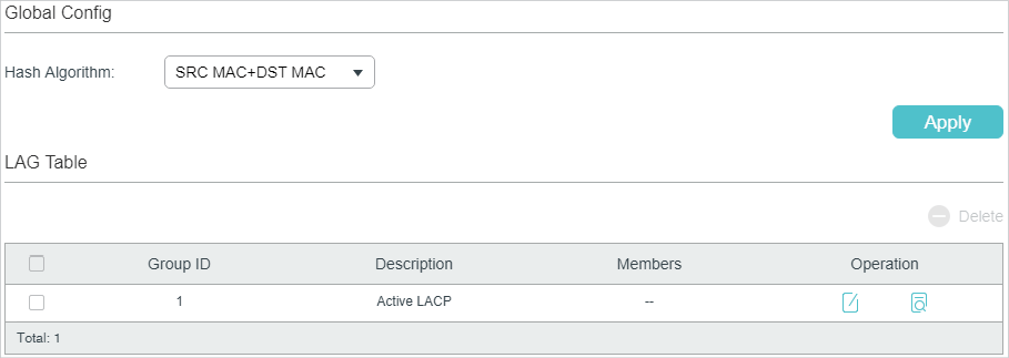
In the Global Config section, select the load-balancing algorithm (Hash Algorithm), then click Apply.
|
Hash Algorithm |
Select the Hash Algorithm, based on which the switch can choose the port to forward the received packets. In this way, different data flows are forwarded on different physical links to implement load balancing. There are six options: SRC MAC: The computation is based on the source MAC addresses of the packets. DST MAC: The computation is based on the destination MAC addresses of the packets. SRC MAC+DST MAC: The computation is based on the source and destination MAC addresses of the packets. SRC IP: The computation is based on the source IP addresses of the packets. DST IP: The computation is based on the destination IP addresses of the packets. SRC IP+DST IP: The computation is based on the source and destination IP addresses of the packets. |
Tips:
Load-balancing algorithm is effective only for outgoing traffic. If the data stream is not well shared by each link, you can change the algorithm of the outgoing interface.
Please properly choose the load-balancing algorithm to avoid data stream transferring only on one physical link. For example, Switch A receives packets from several hosts and forwards them to the Server with the fixed MAC address, you can set the algorithm as “SRC MAC” to allow Switch A to determine the forwarding port based on the source MAC addresses of the received packets.
Figure 2-2 Hash Algorithm Configuration
2.1.2Configuring Static LAG or LACP
For one port, you can choose only one LAG mode: Static LAG or LACP. And make sure both ends of a link use the same LAG mode.
Configuring Static LAG
Choose the menu L2 FEATURES > Switching > LAG > Static LAG to load the following page.
Figure 2-3 Static LAG
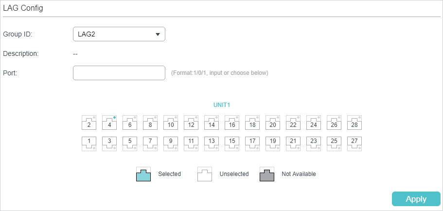
Follow these steps to configure the static LAG:
1)Select an LAG for configuration.
|
Group ID |
Select an LAG for static LAG configuration. |
|
Description |
Displays the LAG mode. |
2)Select the member ports for the LAG. It is multi-optional.
3)Click Apply.
|
|
Note: Clearing all member ports will delete the LAG. |

Configuring LACP
Choose the menu L2 FEATURES > Switching > LAG > LACP to load the following page.
Figure 2-4 LACP Config
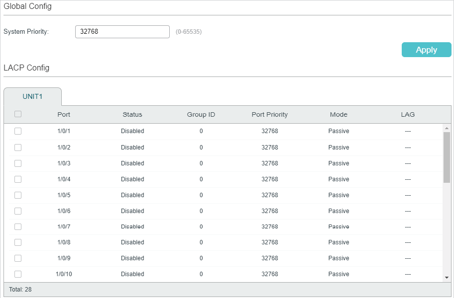
Follow these steps to configure LACP:
1)Specify the system priority for the switch and click Apply.
|
System Priority |
Specify the system priority for the switch. A smaller value means a higher priority. To keep active ports consistent at both ends, you can set the system priority of one device to be higher than that of the other device. The device with higher priority will determine its active ports, and the other device can select its active ports according to the selection result of the device with higher priority. If the two ends have the same system priority value, the device with a smaller MAC address has the higher priority. |
2)Select member ports for the LAG and configure the related parameters. Click Apply.
|
Group ID |
Specify the group ID of the LAG. Note that the group ID of other static LAGs cannot be set as this value. The valid value of the Group ID is determined by the maximum number of LAGs supported by your switch. For example, if your switch supports up to 14 LAGs, the valid value ranges from 1 to 14. |
|
Port Priority (0-65535) |
Specify the Port Priority. A smaller value means a higher port priority. The port with higher priority in an LAG will be selected as the working port to forward data, and at most eight ports can work simultaneously. If two ports have the same priority value, the port with a smaller port number has the higher priority. |
|
Mode |
Select the LACP mode for the port. In LACP, the switch uses LACPDU (Link Aggregation Control Protocol Data Unit) to negotiate the parameters with the peer end. In this way, the two ends select active ports and form the aggregation link. The LACP mode determines whether the port will take the initiative to send the LACPDU. There are two modes: Passive: The port will not send LACPDU before receiving the LACPDU from the peer end. Active: The port will take the initiative to send LACPDU. |
|
Status |
Enable the LACP function of the port. By default, it is disabled. |
2.2Using the CLI
2.2.1Configuring Load-balancing Algorithm
Follow these steps to configure the load-balancing algorithm:
|
Step 1 |
configure Enter global configuration mode. |
|
Step 2 |
port-channel load-balance { src-mac | dst-mac | src-dst-mac | src-ip | dst-ip | src-dst-ip } Select the Hash Algorithm. The switch will choose the ports to transfer the packets based on the Hash Algorithm. In this way, different data flows are forwarded on different physical links to implement load balancing. src-mac: The computation is based on the source MAC addresses of the packets. dst-mac: The computation is based on the destination MAC addresses of the packets. src-dst-mac: The computation is based on the source and destination MAC addresses of the packets. src-ip: The computation is based on the source IP addresses of the packets. dst-ip: The computation is based on the destination IP addresses of the packets. src-dst-ip: The computation is based on the source and destination IP addresses of the packets. |
|
Step 3 |
show etherchannel load-balance Verify the configuration of load-balancing algorithm. |
|
Step 4 |
end Return to privileged EXEC mode. |
|
Step 5 |
copy running-config startup-config Save the settings in the configuration file. |
The following example shows how to set the global load-balancing mode as src-dst-mac:
Switch#configure
Switch(config)#port-channel load-balance src-dst-mac
Switch(config)#show etherchannel load-balance
EtherChannel Load-Balancing Configuration: src-dst-mac
EtherChannel Load-Balancing Addresses Used Per-Protocol:
Non-IP: Source XOR Destination MAC address
IPv4: Source XOR Destination MAC address
IPv6: Source XOR Destination MAC address
Switch(config)#end
Switch#copy running-config startup-config
2.2.2Configuring Static LAG or LACP
You can choose only one LAG mode for a port: Static LAG or LACP. And make sure both ends of a link use the same LAG mode.
Configuring Static LAG
Follow these steps to configure static LAG:
|
Step 1 |
configure Enter global configuration mode. |
|
Step 2 |
interface {fastEthernet port | range fastEthernet port-list | gigabitEthernet port | range gigabitEthernet port-list | ten-gigabitEthernet port | range ten-gigabitEthernet port-list ] Enter interface configuration mode. |
|
Step 3 |
channel-group num mode on Add the port to a static LAG. num: The group ID of the LAG. |
|
Step 4 |
show etherchannel num summary Verify the configuration of the static LAG. num: The group ID of the LAG. |
|
Step 5 |
end Return to privileged EXEC mode. |
|
Step 6 |
copy running-config startup-config Save the settings in the configuration file. |
The following example shows how to add ports1/0/5-8 to LAG 2 and set the mode as static LAG:
Switch#configure
Switch(config)#interface range gigabitEthernet 1/0/5-8
Switch(config-if-range)#channel-group 2 mode on
Switch(config-if-range)#show etherchannel 2 summary
Flags: D - down P - bundled in port-channel U - in use
I - stand-alone H - hot-standby(LACP only) s - suspended
R - layer3 S - layer2 f - failed to allocate aggregator
u - unsuitable for bundling w - waiting to be aggregated d - default port
Group Port-channel Protocol Ports
----- --------- ------- -------------------------------
2 Po2(S) - Gi1/0/5(D) Gi1/0/6(D) Gi1/0/7(D) Gi1/0/8(D)
Switch(config-if-range)#end
Switch#copy running-config startup-config
Configuring LACP
Follow these steps to configure LACP:
|
Step 1 |
configure Enter global configuration mode. |
|
Step 2 |
lacp system-priority pri Specify the system priority for the switch. To keep active ports consistent at both ends, you can set the priority of one device to be higher than that of the other device. The device with higher priority will determine its active ports, and the other device can select its active ports according to the selection result of the device with higher priority. If the two ends have the same system priority value, the end with a smaller MAC address has the higher priority. pri: System priority. The valid values are from 0 to 65535, and the default value is 32768. A smaller value means a higher device priority. |
|
Step 3 |
interface {fastEthernet port | range fastEthernet port-list | gigabitEthernet port | range gigabitEthernet port-list | ten-gigabitEthernet port | range ten-gigabitEthernet port-list ] Enter interface configuration mode. |
|
Step 4 |
channel-group num mode { active | passive } Add the port to an LAG and set the mode as LACP. num: The group ID of the LAG. mode: LAG mode. Here you need to select LACP mode: active or passive. In LACP, the switch uses LACPDU (Link Aggregation Control Protocol Data Unit) to negotiate the parameters with the peer end. In this way, the two ends select active ports and form the aggregation link. The LACP mode determines whether the port will take the initiative to send the LACPDU. passive: The port will not send LACPDU before receiving the LACPDU from the peer end. active: The port will take the initiative to send LACPDU. |
|
Step 5 |
lacp port-priority pri Specify the Port Priority. The port with higher priority in an LAG will be selected as the working port. If two ports have the same priority value, the port with a smaller port number has the higher priority. pri: Port priority. The valid values are from 0 to 65535, and the default value is 32768. A smaller value means a higher port priority. |
|
Step 6 |
show lacp sys-id Verify the global system priority. |
|
Step 7 |
show lacp internal Verify the LACP configuration of the local switch. |
|
Step 8 |
end Return to privileged EXEC mode. |
|
Step 9 |
copy running-config startup-config Save the settings in the configuration file. |
The following example shows how to specify the system priority of the switch as 2:
Switch#configure
Switch(config)#lacp system-priority 2
Switch(config)#show lacp sys-id
2, 000a.eb13.2397
Switch(config)#end
Switch#copy running-config startup-config
The following example shows how to add ports 1/0/1-4 to LAG 6, set the mode as LACP, and select the LACPDU sending mode as active:
Switch#configure
Switch(config)#interface range gigabitEthernet 1/0/1-4
Switch(config-if-range)#channel-group 6 mode active
Switch(config-if-range)#show lacp internal
Flags: S - Device is requesting Slow LACPDUs
F - Device is requesting Fast LACPDUs
A - Device is in active mode
P - Device is in passive mode
Channel group 6
Port Flags State LACP Port Priority Admin Key Oper Key Port Number Port State
Gi1/0/1 SA Up 32768 0x6 0x4b1 0x1 0x7d
Gi1/0/2 SA Down 32768 0x6 0 0x2 0x45
Gi1/0/3 SA Down 32768 0x6 0 0x3 0x45
Gi1/0/4 SA Down 32768 0x6 0 0x4 0x45
Switch(config-if-range)#end
Switch#copy running-config startup-config
3.1Example for Static LAG
3.1.1Network Requirements
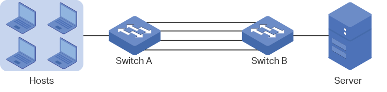
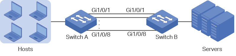
As shown below, hosts and servers are connected to switch A and switch B, and heavy traffic is transmitted between the two switches. To achieve high speed and reliability of data transmission, users need to improve the bandwidth and redundancy of the link between the two switches.
Figure 3-1 Network Topology
3.1.2Configuration Scheme
LAG function can bundle multiple physical ports into one logical interface to increase bandwidth and improve reliability. In this case we can configure static LAG to meet the requirement.
The overview of the configuration is as follows:
1)Considering there are multiple devices on each end, configure the load-balancing algorithm as ‘SRC MAC+DST MAC’.
2)Add ports 1/0/1-8 to a static LAG.
Demonstrated with T2600G-28TS, the following sections provide configuration procedure in two ways: using the GUI and using the CLI.
3.1.3Using the GUI
The configurations of switch A and switch B are similar. The following introductions take switch A as an example.
1)Choose the menu L2 FEATURES > Switching > LAG > LAG Table to load the following page. Select the hash algorithm as ‘SRC MAC+DST MAC’.
Figure 3-2 Global Configuration

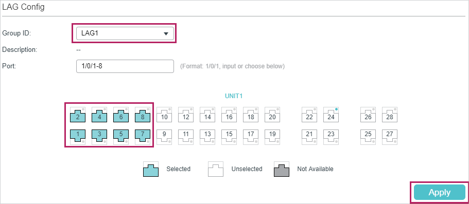
2)Choose the menu L2 FEATURES > Switching > LAG > Static LAG to load the following page. Select LAG 1 and add ports 1/0/1-8 to LAG 1.
Figure 3-3 System Priority Configuration
3)Click  to save the settings.
3.1.4Using the CLI
The configurations of switch A and switch B are similar. The following introductions take switch A as an example.
1)Configure the load-balancing algorithm as “src-dst-mac”.
Switch#configure
Switch(config)#port-channel load-balance src-dst-mac
2)Add ports 1/0/1-8 to static LAG 1.
Switch(config)#interface range gigabitEthernet 1/0/1-8
Switch(config-if-range)#channel-group 1 mode on
Switch(config-if)#end
Switch#copy running-config startup-config
Verify the Configuration
Switch#show etherchannel 1 summary
Flags: D - down P - bundled in port-channel U - in use
I - stand-alone H - hot-standby(LACP only) s - suspended
R - layer3 S - layer2 f - failed to allocate aggregator
u - unsuitable for bundling w - waiting to be aggregated d - default port
Group Port-channel Protocol Ports
----- --------- ------- -------------------------------
1 Po2(S) - Gi1/0/1(D) Gi1/0/2(D) Gi1/0/3(D) Gi1/0/4(D)
Gi1/0/5(D) Gi1/0/6(D) Gi1/0/7(D) Gi1/0/8(D)
3.2Example for LACP
3.2.1Network Requirements
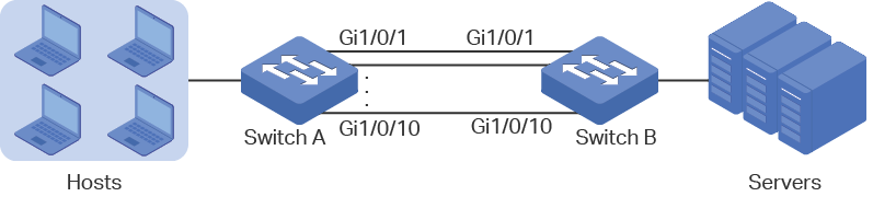
As shown below, hosts and servers are connected to switch A and switch B, and heavy traffic is transmitted between the two switches. To achieve high speed and reliability of data transmission, users need to improve the bandwidth and redundancy of the link between the two switches.
Figure 3-4 Network Topology
3.2.2Configuration Scheme
LAG function can bundle multiple physical ports into one logical interface to increase bandwidth and improve reliability. We can configure LACP to meet the requirement.
The overview of the configuration is as follows:
1)Considering there are multiple devices on each end, configure the load-balancing algorithm as ‘SRC MAC+DST MAC’.
2)Specify the system priority for the switches. Here we choose switch A as the dominate device and specify a higher system priority for it.
3)Add ports 1/0/1-10 to the LAG and set the mode as LACP.
4)Specify a lower port priority for ports 1/0/9-10 to set them as the backup ports. When any of ports 1/0/1-8 is down, the backup ports will automatically be enabled to transmit data.
Demonstrated with T2600G-28TS, the following sections provide configuration procedure in two ways: using the GUI and using the CLI.
3.2.3Using the GUI
The configurations of switch A and switch B are similar. The following introductions take switch A as an example.
1)Choose the menu L2 FEATURES > Switching > LAG > LAG Table to load the following page. Select the hash algorithm as ‘SRC MAC+DST MAC’.
Figure 3-5 Global Configuration
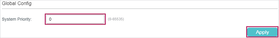
2)Choose the menu L2 FEATURES > Switching > LAG > LACP Config to load the following page. In the Global Config section, specify the system priority of Switch A as 0 and Click Apply. Remember to ensure that the system priority value of Switch B is bigger than 0.
Figure 3-6 System Priority Configuration
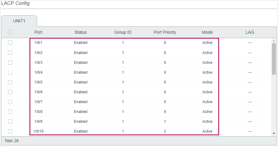
3)In the LACP Config section, select ports 1/0/1-10, and respectively set the status, group ID, port priority and mode for each port as follows.
Figure 3-7 LACP Configuration
4)Click  to save the settings.
3.2.4Using the CLI
The configurations of switch A and switch B are similar. The following introductions take switch A as an example.
1)Configure the load-balancing algorithm as “src-dst-mac”.
Switch#configure
Switch(config)#port-channel load-balance src-dst-mac
2)Specify the system priority of Switch A as 0. Remember to ensure that the system priority value of Switch B is bigger than 0.
Switch(config)#lacp system-priority 0
3)Add ports 1/0/1-8 to LAG 1 and set the mode as LACP. Then specify the port priority as 0 to make them active.
Switch(config)#interface range gigabitEthernet 1/0/1-8
Switch(config-if-range)#channel-group 1 mode active
Switch(config-if-range)#lacp port-priority 0
Switch(config-if-range)#exit
4)Add port 1/0/9 to LAG 1 and set the mode as LACP. Then specify the port priority as 1 to set it as a backup port. When any of the active ports is down, this port will be preferentially selected to work as an active port.
Switch(config)#interface gigabitEthernet 1/0/9
Switch(config-if)#channel-group 1 mode active
Switch(config-if)#lacp port-priority 1
Switch(config-if)#exit
5)Add port 1/0/10 to LAG 1 and set the mode as LACP. Then specify the port priority as 2 to set it as a backup port. The priority of this port is lower than port 1/0/9.
Switch(config)#interface gigabitEthernet 1/0/10
Switch(config-if)#channel-group 1 mode active
Switch(config-if)#lacp port-priority 2
Switch(config-if)#end
Switch#copy running-config startup-config
Verify the Configuration
Verify the system priority:
Switch#show lacp sys-id
0, 000a.eb13.2397
Verify the LACP configuration:
Switch#show lacp internal
Flags: S - Device is requesting Slow LACPDUs
F - Device is requesting Fast LACPDUs
A - Device is in active mode
P - Device is in passive mode
Channel group 1
Port Flags State LACP Port Priority Admin Key Oper Key Port Number Port State
Gi1/0/1 SA Down 0 0x1 0 0x1 0x45
Gi1/0/2 SA Down 0 0x1 0 0x2 0x45
Gi1/0/3 SA Down 0 0x1 0 0x3 0x45
Gi1/0/4 SA Down 0 0x1 0 0x4 0x45
Gi1/0/5 SA Down 0 0x1 0 0x5 0x45
Gi1/0/6 SA Down 0 0x1 0 0x6 0x45
Gi1/0/7 SA Down 0 0x1 0 0x7 0x45
Gi1/0/8 SA Down 0 0x1 0 0x8 0x45
Gi1/0/9 SA Down 1 0x1 0 0x9 0x45
Gi1/0/10 SA Down 2 0x1 0 0xa 0x45
Default settings of Switching are listed in the following tables.
Table 4-1Default Settings of LAG
|
Parameter |
Default Setting |
|
LAG Table |
|
|
Hash Algorithm |
SRC MAC+DST MAC |
|
LACP Config |
|
|
System Priority |
32768 |
|
Admin Key |
0 |
|
Port Priority |
32768 |
|
Mode |
Passive |
|
Status |
Disable |