


How to Manage CAPs in Different subnets Using TP-Link AC Controller (Using TP-Link AC Controller as the DHCP Server for the CAPs)
In the network topology below, there are three VLANs (three subnets), which are VLAN1 (192.168.0.0/24), VLAN2 (192.168.1.0/24) and VLAN3 (172.30.30.0/24). These three VLANs (three subnets) are divided by TP-Link L3 Switch (T2600G-28TS). Now we want TP-Link AC controller AC500 in VLAN1 (192.168.0.0/24) to manage CAP in VLAN2 (192.168.1.0/24). The gateway Router is TP-Link SMB router TL-R480T+.

This document will introduce how to manage CAPs in different subnets using TP-Link AC controller (using TP-Link AC controller as the DHCP server for the CAPs). For the configurations of multi-nets NAT function on TP-LINK SMB router, please refer to: https://www.tp-link.com/support/faq/887/ .
Step1. Configurations on TP-Link AC controller
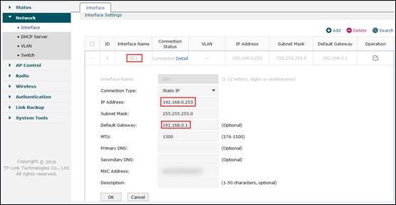
1.1 Please connect TP-Link AC controller (port 5) to TP-Link L3 switch T2600G-28TS (port 16), and configure the interface IP address of AC controller’s default VLAN1 as 192.168.0.253. At the same time, please set AC controller’s default gateway as 192.168.0.1.
1.2 Set the link type of AC controller’s port 5 as Trunk.

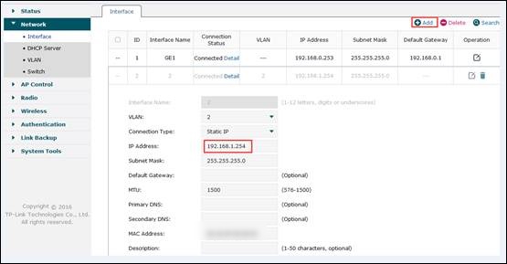
1.3 Add VLAN2 on AC controller, and include Port 5 (TAG).

1.4 Configure the interface IP address of VLAN2 on AC controller as 192.168.1.254.

1.5 Enable DHCP function and create a DHCP pool for VLAN2 (192.168.1.0/24), and Target is “For AP and Client”.

Step2. Settings on Layer 3 switch
2.1 Create VLAN2 and VLAN3, and set port 16 as trunk port. VLAN2 includes port 4 and port16, and VLAN3 includes port7. The detailed VLAN settings are shown as below.


2.2 Configure interface IP addresses for VLAN2 and VLAN3 shown as below.

2.3 Configure the default static routing entry shown as below.

Step3. Switch FIT mode on CAP, and connect CAP to T2600G-28TS (port 4).
Step4. Configurations on Gateway Router TL-R480T+
4.1 Configure Static Routing for VLAN2 (192.168.1.0/24) subnet.

4.2 Configure Multi-nets NAT for VLAN2 (192.168.1.0/24) subnet.

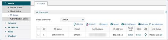
Step5. After all configurations, we can check CAP’s status in AC controller’s “AP Status” page. Here the following screenshot shows the CAP in VLAN2 (192.168.1.0/24) subnet managed by AC controller in VLAN 1 (192.168.0.0/24) subnet.
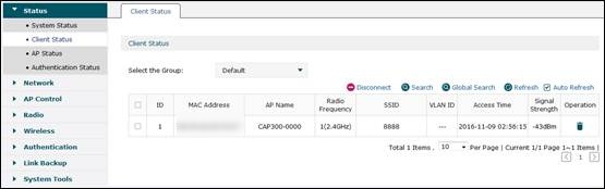
Create a SSID, bind it to the CAPs and connect your client device to CAP’s wireless network to see if you can go to Internet normally. It turns out you can go to Internet normally and AC controller can manage CAPs in different subnets.


Q&A
What if AC can discover CAP, but client device has no Internet Access?
Answer: Check if you have set up multi-nets NAT function on gateway router and set up the correct static routing entries on L3 switch. Please refer to: https://www.tp-link.com/support/faq/887/ . Also, please check the DHCP Server Settings, and make sure you have set the right Default Gateway and DNS Server IP.
Why my client device cannot get the IP address from DHCP server?
Answer: Please make sure that you have chosen “For AP and Client” as AC controller DHCP server’s Target.

Is this faq useful?
Your feedback helps improve this site.
1.0_1505290145255s.jpg)
1.0_1505290425728l.jpg)
TP-Link Community
Still need help? Search for answers, ask questions, and get help from TP-Link experts and other users around the world.