How to connect and configure external devices when using license plate recognition camera
Contents
An overview of the I/O Interface
Alarm Input/Output Wiring (for LPR Applications)
Alarm Input/Output Configuration
Introduction
License plate recognition (LPR) cameras are commonly used at vehicle entrances and exits together with devices such as barrier gates, anti-smashing radars, and loop detectors. This guide provides wiring instructions and configuration for coordinated operation with these external devices.
Requirements
- VIGI InSight LPR345Z
- External Alarm Input Devices (e.g., loop detectors, anti-smashing radars)
- External Alarm Output Devices (e.g., barrier gates)
Configuration
To complete the configuration, you need to finish both the alarm input/output wiring and software configurations.
An overview of the I/O Interface
The following table describes the I/O interface of VIGI License plate recognition camera.
|
Interface |
Function |
Description |
|
AUDIO OUT |
Audio Output |
Outputs audio signals from the camera. Used to connect external speakers. |
|
AUDIO IN |
Audio Input |
Receives audio signals for the camera. Used to connect external microphones. |
|
ALARM OUT |
Alarm Output |
1. Connects to the barrier gate’s open/close control terminal using the OUT and adjacent G terminals. The camera has only one alarm output channel (Alarm OUT + G). 2. Sends alarm output signals to external devices such as strobes or sirens. |
|
ALARM IN |
Alarm Input |
1. Connects to devices such as anti-smashing radars or loop detectors using the IN and adjacent G terminals. The camera has only one alarm in channel (Alarm In + G). 2. Receives alarm input signals from sensors or other alarm input devices. |
|
RS485 |
Serial Interface |
Reserved Interface |
Alarm Input/Output Wiring (for LPR Applications)
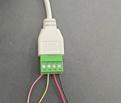
The Alarm interface includes the IN, G, OUT, and G terminals, as shown in the figure below. Connect the terminals to external devices as needed. The following are three typical wiring scenarios:
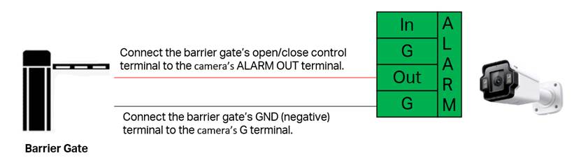
Scenario 1: Using Only the Alarm Out Interface to Control External Devices
When the IPC is used as the control device, connect the camera’s ALARM OUT terminal to either the “open” or “close” control terminal on the barrier gate. Connect the G terminal on the camera to the G terminal on the barrier gate.
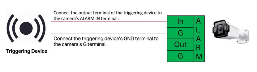
Scenario 2: Scenario 2: Using Only the Alarm In Interface to Trigger License Plate Capture
When the IPC is used only for license plate capture, connect the OUT terminal of the triggering device, such as a vehicle detector, loop detector, or manual trigger button—to the camera’s ALARM IN terminal. Connect the GND terminal of the triggering device to the G terminal on the camera.
Scenario 3: Using Both Alarm In and Alarm Out Interfaces
When the camera is connected to two different external devices—one for input and one for output—wire each device according to the methods described in Scenario 1 and Scenario 2. Connect the triggering device to the ALARM IN terminals and connect the controlled device (such as a barrier gate) to the ALARM OUT terminals.
Alarm Input/Output Configuration
Follow the steps below to configure the camera’s Alarm In and Alarm Out functions, and enable the required linkage features as needed.
Alarm Output Configuration
Step 1. After connecting the external device to the ALARM OUT terminals, access the camera’s web management interface by entering its IP address in a web browser.
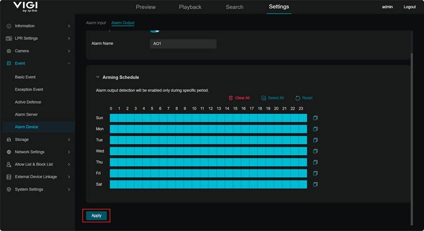
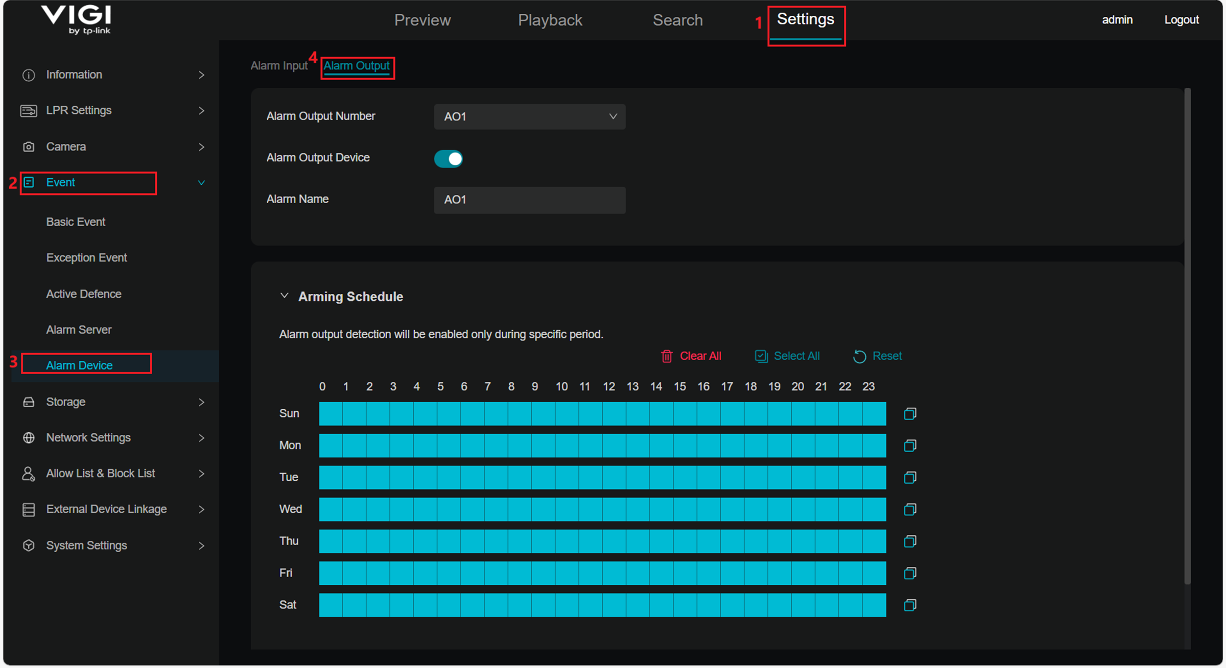
Step 2. Navigate to Settings > Event > Alarm Device > Alarm Output page. Enable the Alarm Out Device switch, enter an Alarm Name for the alarm output interface, and configure the Arming Schedule. Alarm output detection will be enabled only during the configured period.
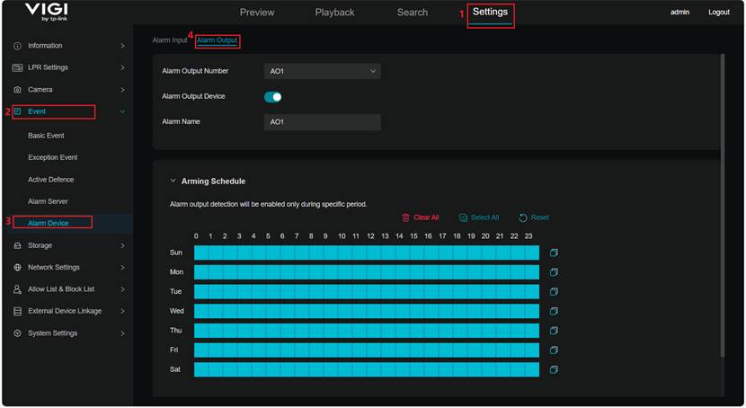
Step 3. Click Apply to save the Alarm Out settings.
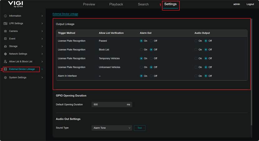
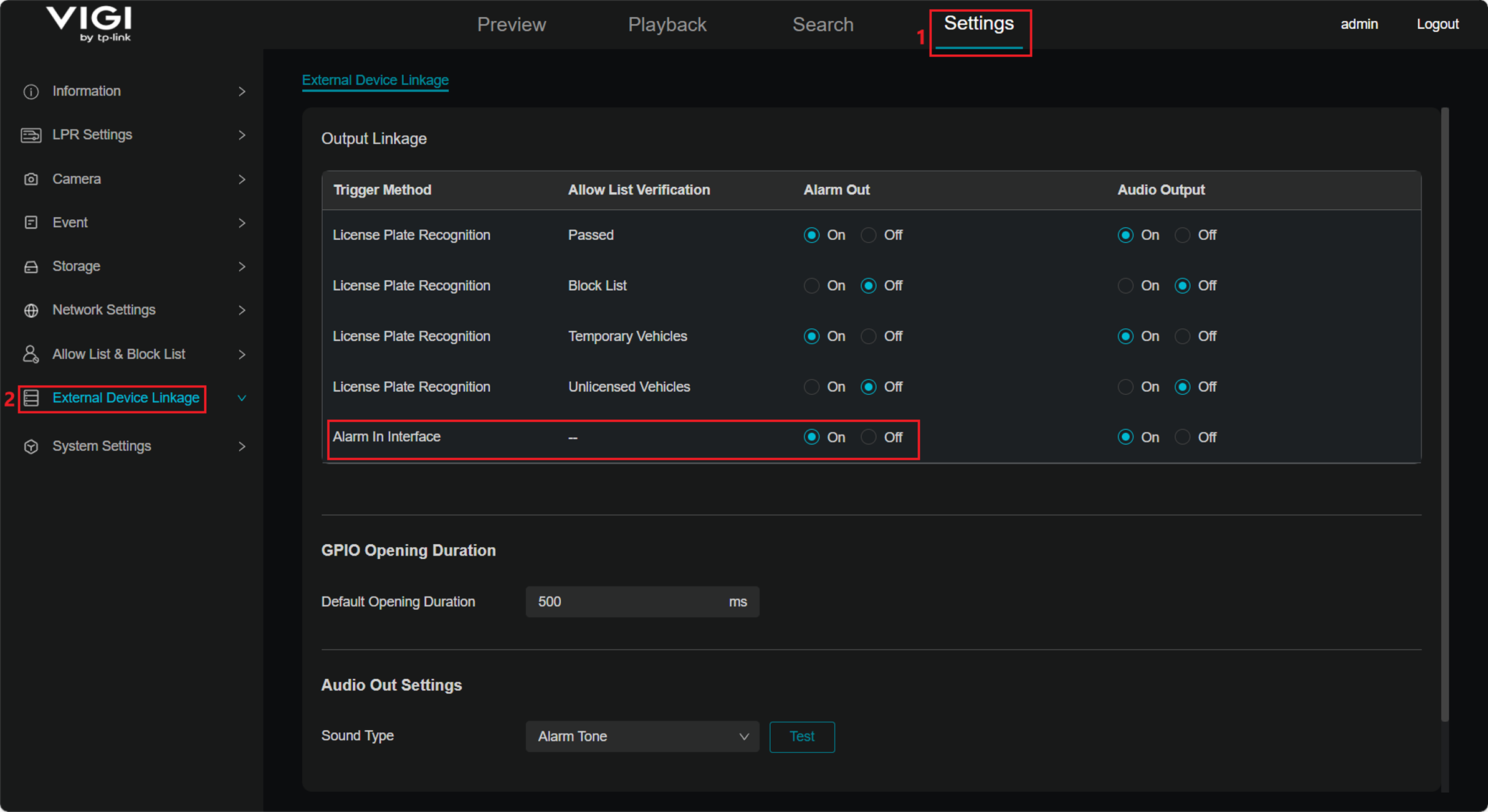
Step 4. Navigate to Settings > External Device Linkage and configure the Alarm Out linkage rules as needed.
The first column indicates the trigger method, and the second column shows the allow-list verification rule. The third column defines whether the Alarm Out output will be turned on or off (that is, outputting a high-level or low-level signal), and the Audio Output column specifies whether audio output will be enabled. When configuring linkage rules based on license plate recognition, users can choose different output behaviors under different conditions according to the actual scenario. Using the Alarm Out interface to control a barrier gate as an example, the configuration shown above indicates:
When a detected license plate belongs to the Passed or is categorized as a Temporary Vehicle:
Alarm Out is set to On, meaning the camera outputs a high-level signal to trigger the barrier gate to open. Audio Output is also enabled, activating any connected audio device.
When a detected license plate belongs to the Block List or is categorized as an Unlicensed Vehicle:
Alarm Out is set to Off, meaning the camera outputs a low-level signal and the barrier gate remains closed. Audio Output is also disabled.
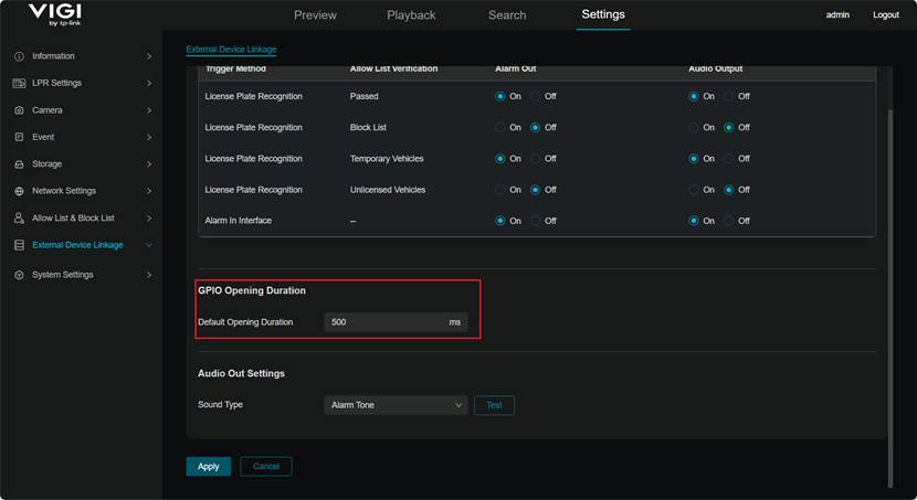
Step 5. The Default Opening Duration can be adjusted to ensure successful triggering when external devices have different sensitivity levels.
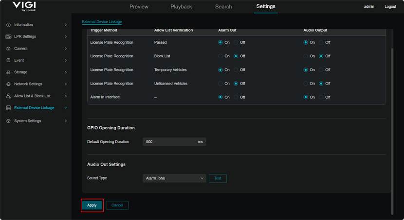
Step 6. Click Apply to save the External Device Linkage configuration.
Step 7. Navigate to the Preview page. The Alarm Output button can be used to manually trigger the alarm output, and the barrier gate can then be checked to confirm whether it opens or closes as expected.
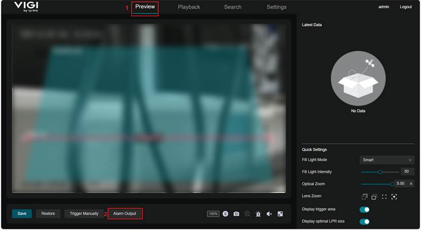
Note: A clicking sound inside the camera when the Alarm Output button is pressed is normal.
Alarm Input Configuration
Step 1. After connecting the external device to the ALARM IN terminals, access the camera’s web management interface by entering its IP address in a web browser.
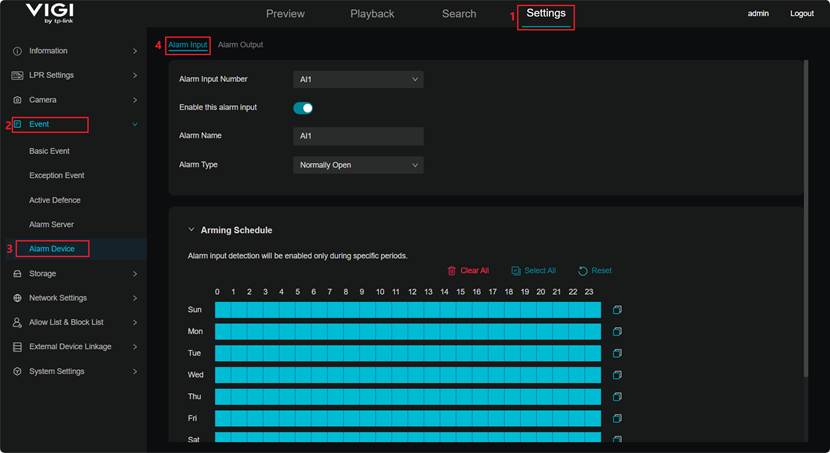
Step 2. Navigate to Settings > Event > Alarm Device > Alarm Input. Enable the Alarm Input switch, set the Alarm Name as needed, and configure the Alarm Type as Normally Open or Normally Closed. Configure the Arming Schedule; alarm input detection will be enabled only during the specified periods.
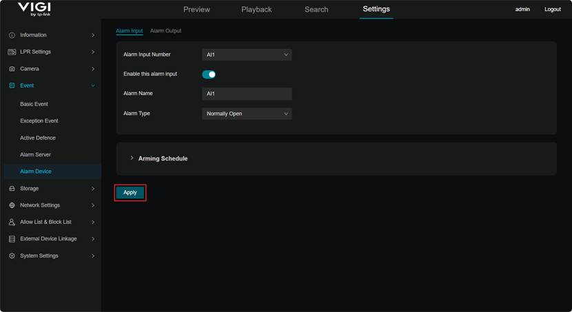
Step 3. Click Apply to save the Alarm Input configuration.
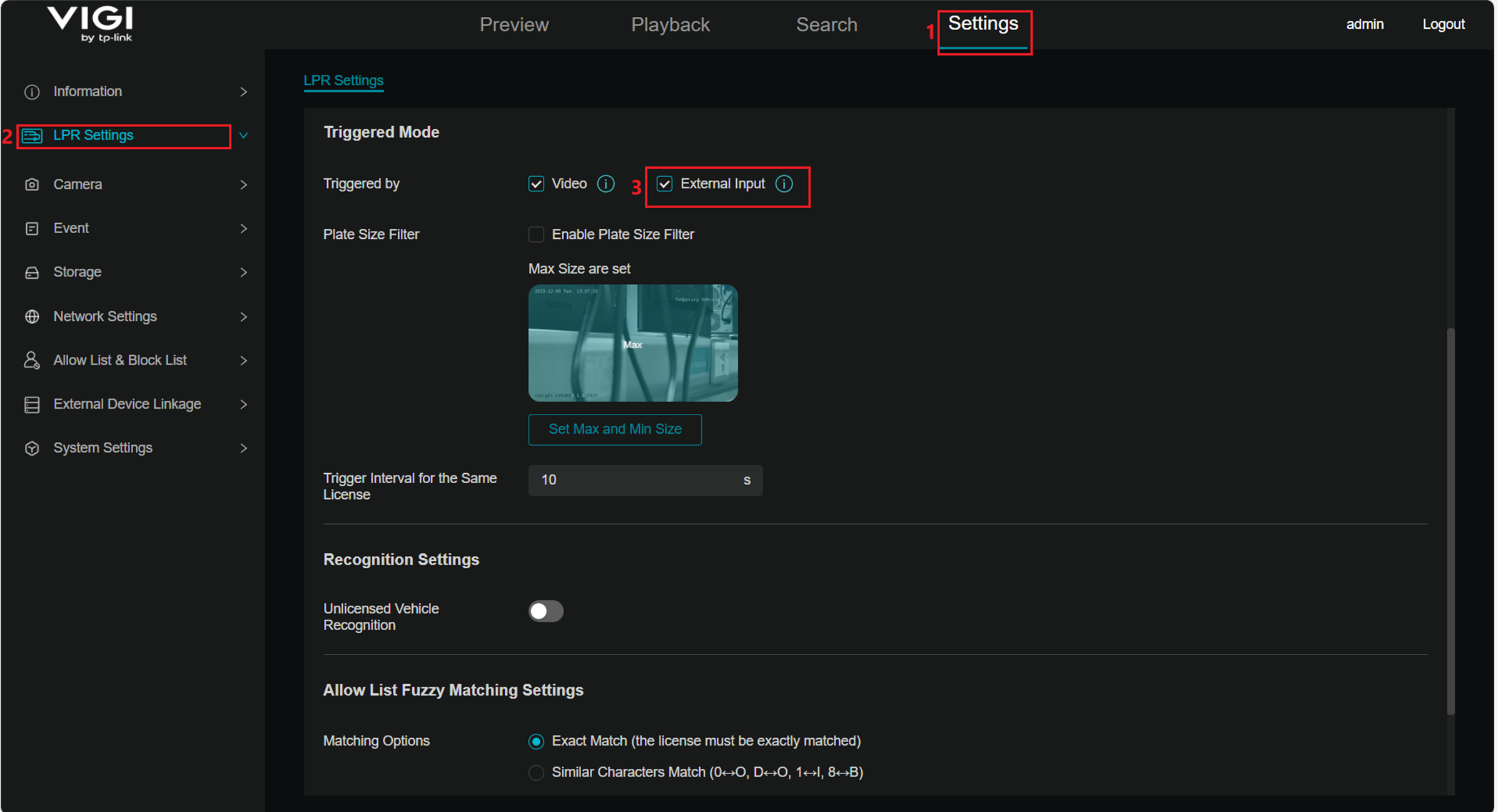
Step 4. Navigate to Settings > LPR Settings and check External Input. When a signal is received at the Alarm Input terminals, the camera will start license plate recognition. Click Apply to save the configuration.
Step 5. (optional) When an Alarm In signal is received and linkage to an Alarm Out device is required, navigate to Settings > Event > Alarm Device > Alarm Output to configure the Alarm Out settings, such as enabling the Alarm Out device switch. Click Apply to save the Alarm Out configuration.
Step 6. (optional) Navigate to Settings > External Device Linkage and configure the Alarm In linkage to trigger a high-level Alarm Out output. When Trigger Method is set to Alarm In Interface, the Alarm Out status is set to On. For example, when a vehicle activates a triggering device such as a radar sensor, the camera will capture a vehicle image and the Alarm Out output will provide a high-level signal to trigger the barrier gate to open.
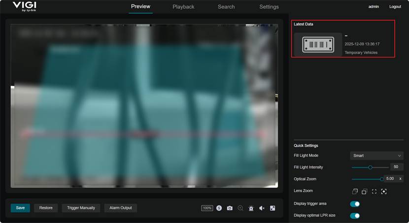
Step 7. After triggering the external alarm in device, check whether an image has been captured by confirming it in the Last Data list on the Preview page.
Conclusion
With the steps above, you have successfully connected and configured external devices for the license plate recognition camera.
Get to know more details of each function and configuration please go to Download Center to download the manual of your product.
Is this faq useful?
Your feedback helps improve this site.
TP-Link Community
Still need help? Search for answers, ask questions, and get help from TP-Link experts and other users around the world.