


How to configure switch as DHCP server on Standalone mode
At times you may want to configure your TP-Link switch to act as the DHCP server of your network instead of using your router. This FAQ will show you how to do that.
*Note: This FAQ assumes you are using a TP-Link ER605 SMB router. Actions on the router may vary depending on what you are using.
Network Topology:
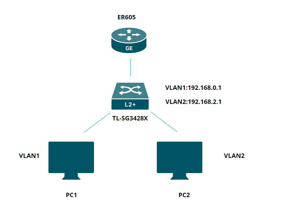
Use router’s IP to log into its Web interface. Go to Network>LAN> DHCP Client List to check switch’s IP.
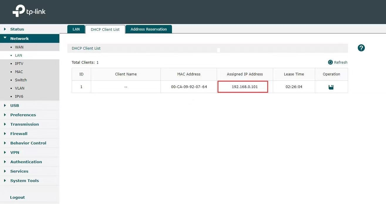
Then use switch’s IP to log in to its web interface.
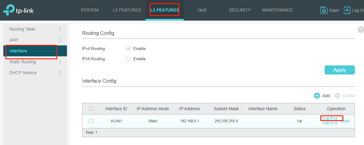
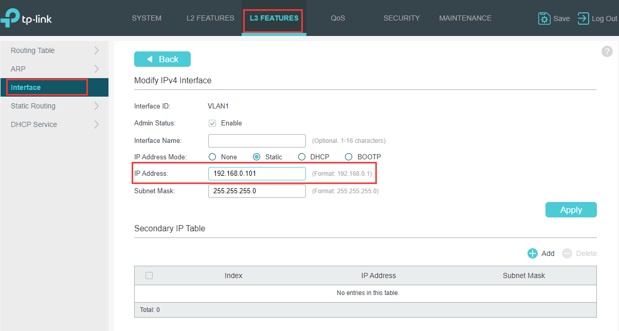
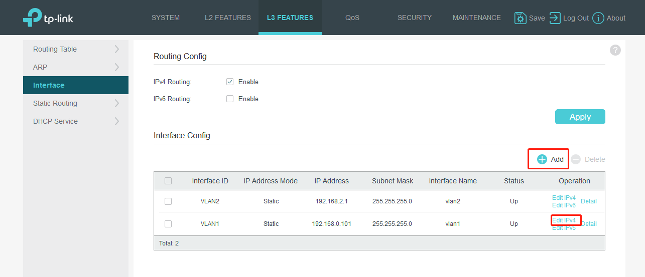
Go to L3 Features>Interface>Edit IPv4 to set the IP address as static for better convenience to log into the switch after router’s DHCP feature being turned off.
If there are two DHCP servers in your network, it will cause chaos on IP assignment, so we need to turn off the router’s DHCP server.
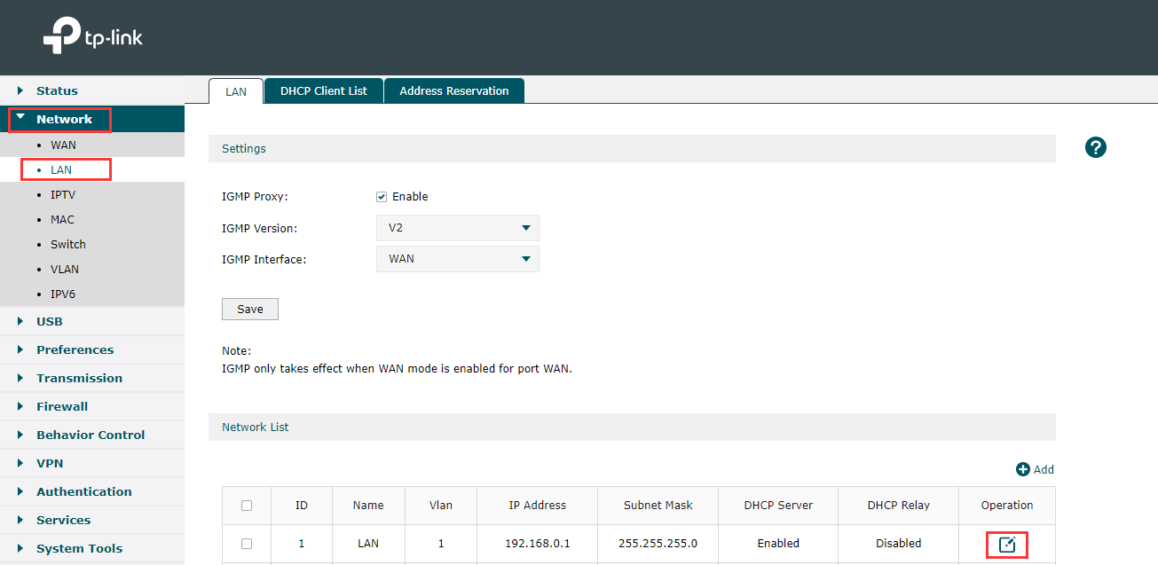
Use router’s IP to log into Web Interface. Go to Network> LAN > Network List and click on edit button.
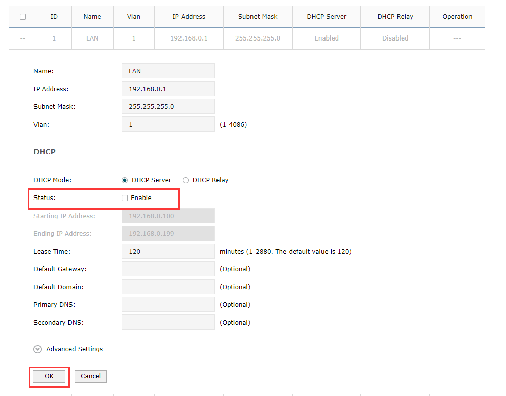
After that find Status under DHCP to uncheck the small box near Enable and click on Ok.
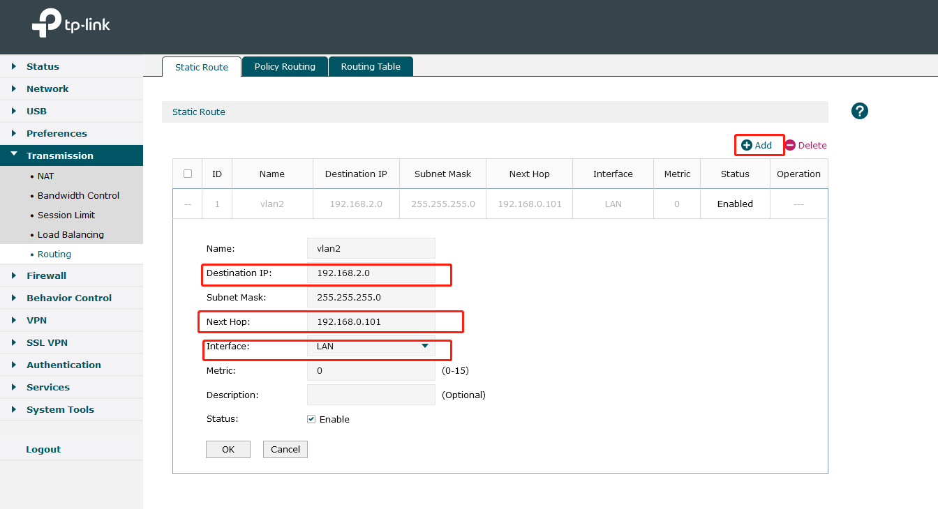
It is necessary for ER605 to configure static routing to know where to deliver the packets to IP addresses of VLAN2. Go to Transmission>Routing>Static Route. Add the following entries.
Next Hop: Fill in 192.168.0.101 which is interface IP of TL-SG3428X.
Destination IP: VLAN 2’s subnet segment.
Interface: Select the default LAN.
There has no need to create VLAN interface 2 to the router, because ER605 is the router supporting Multi-Net NAT automatically.
Note: As VLAN1 is the default Network, here we do not need to add Static Routing Rule for VLAN1.However, if you have created other VLAN, additional Static Routing rule is needed.
As router’s DHCP feature has been turned off in previous step, PC connected to the switch cannot get IP anymore. To successfully log into the switch’s interface, a static IP set to the PC is necessary. The Static IP should be on the same subnet as Switch’s IP (192.168.0.101).
Here is the guidance about how to set a static IP to the PC: https://www.tp-link.com/support/faq/14/
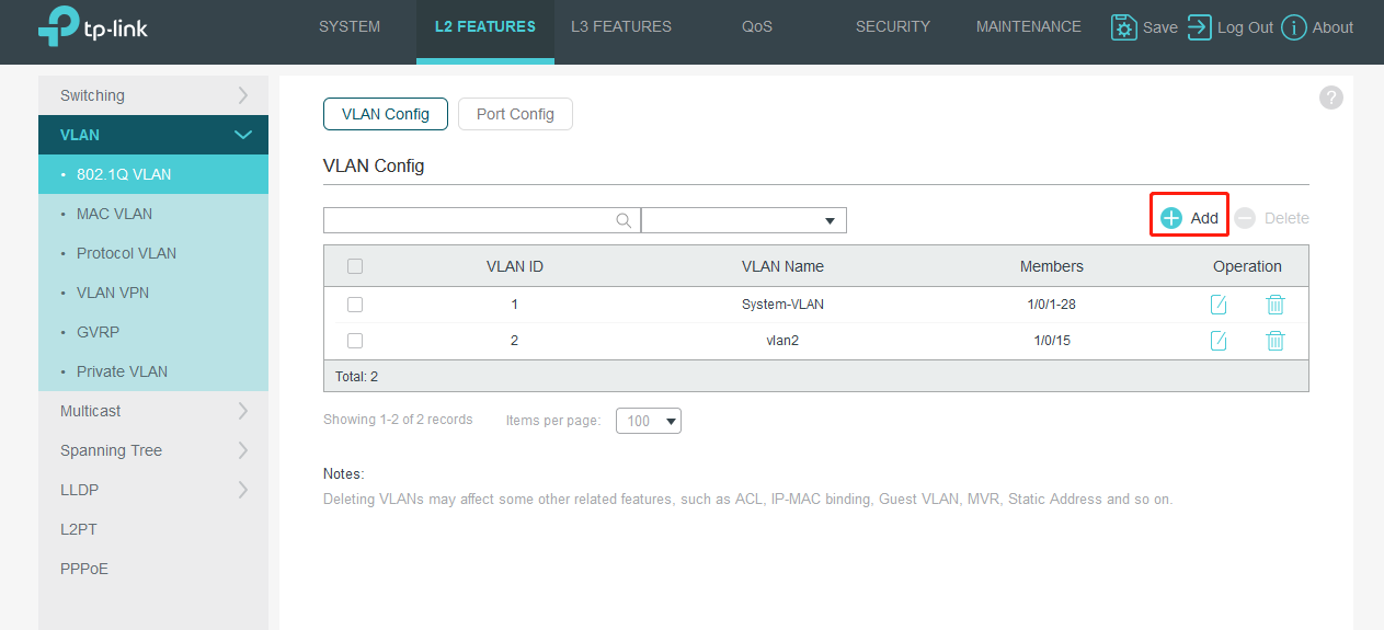
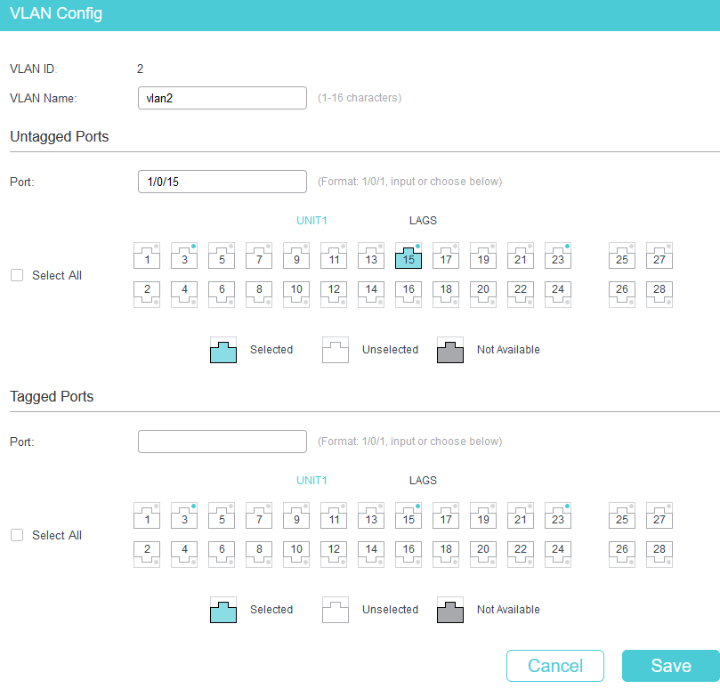
After log into switch’s web interface. Go to L2 FEATURES>VLAN>802.1Q VLAN>VLAN Config, and click Add. Since VLAN1 is the default VLAN, we only need to create VLAN2.
In the pop-up page, we create VLAN ID as 2 and add port 15(connect PC2) as Untagged Port.
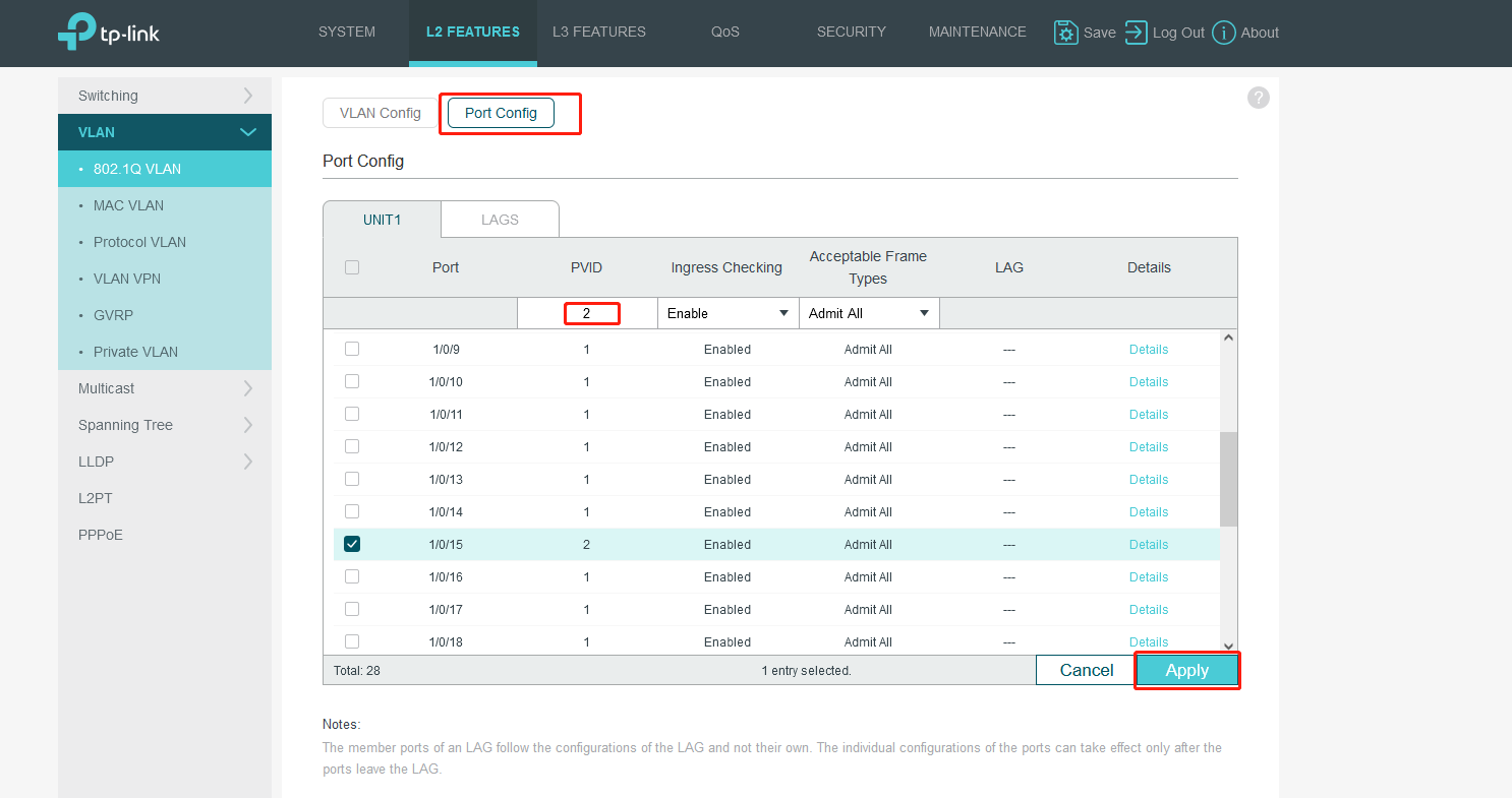
Now we modify the PVID of port15. Turn to Port Config. Then click APPLY.
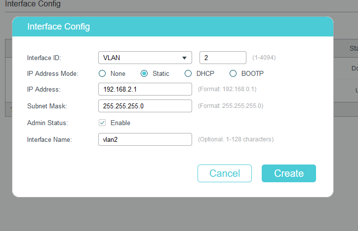
Go to L3 FEATURES>Interface, click Add.
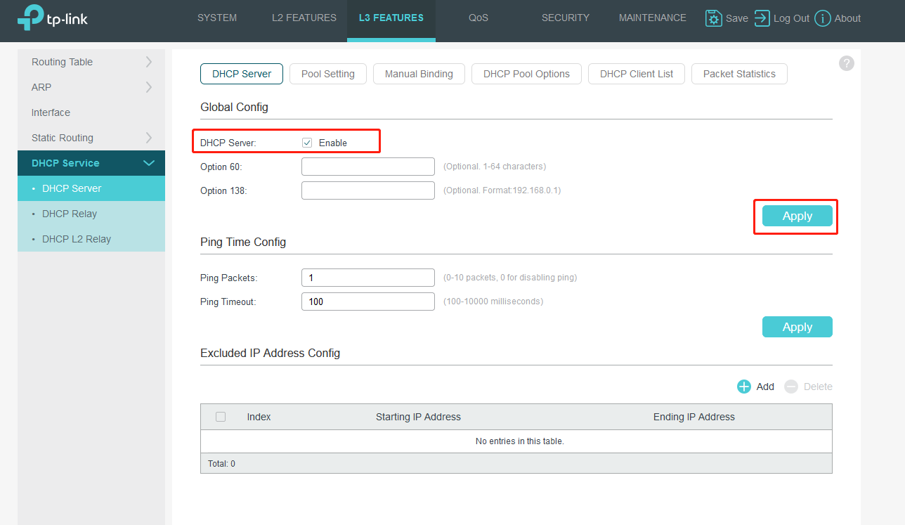
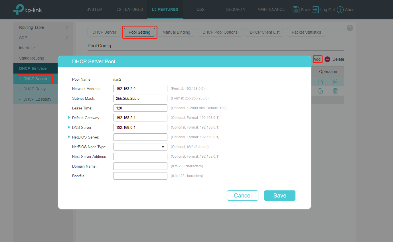
Go to L3 FEATURES>DHCP Service>DHCP Server, enable DHCP server and add DHCP pools for VLAN1 and VLAN2.
Turn to Pool Settings to fill in related information.
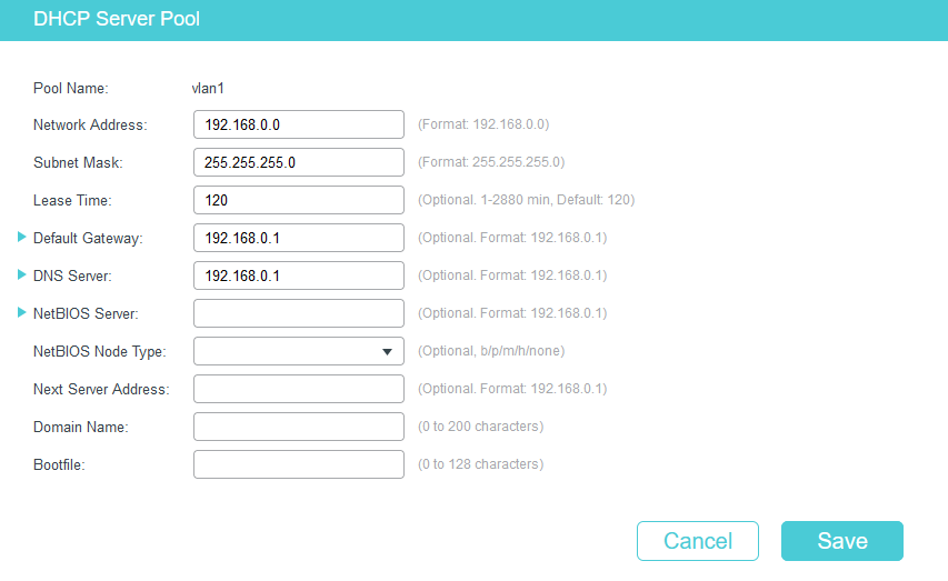
Don’t forget to create VLAN1’s DHCP server pool.
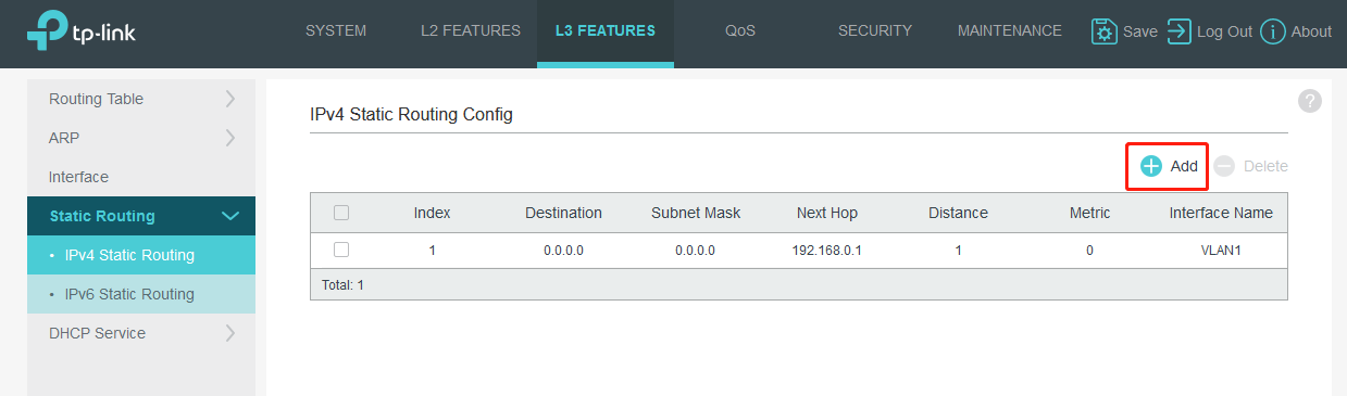
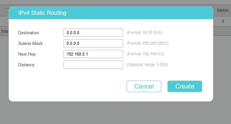
Go to L3 FEATURES>Static Routing>IPv4 Static Routing to add the default route entry. Default route entry is indispensable, because IP packets to Internet whose destination IP is not in the direct routing table will be forwarded according to default route entry. Here we set it as 192.168.0.1,which is the router’s IP.
Note: Don't forget to Click Save button for saving configuration.

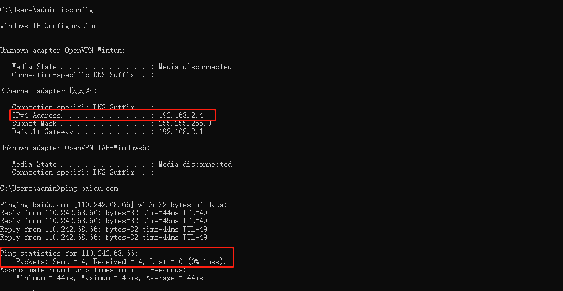
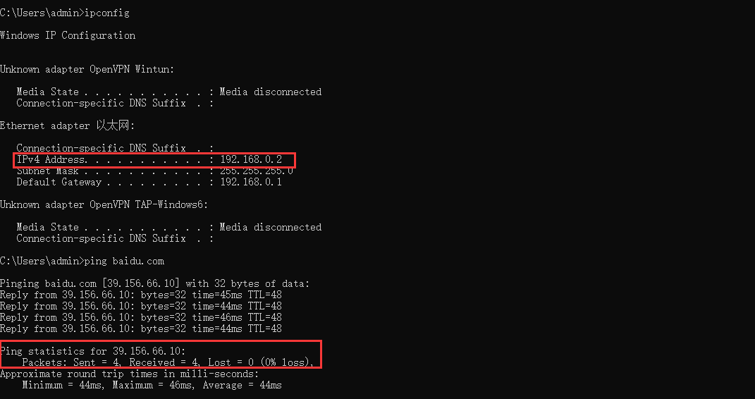
We can check that PC2 can get a IP from 192.168.2.1/24 while PC1 get a IP from 192.168.0.1/24 and they both can access the internet.
PC2 on port 15:
PC1 on any port but port 15:
Полезен ли этот FAQ?
Ваши отзывы помогают улучшить этот сайт.


From United States?
Получайте информацию о продуктах, событиях и услугах для вашего региона.