


How to Capture Wireless Packets via EAP and Omada Controller
Introduction
Wireless Packet Capture are very important diagnostic tool to analyze wireless communication between an Access Point (AP) and clients, and troubleshoot issues such as wireless packets loss, weak signal, and roaming failures., etc.
Omada APs compatible with Omada Controller v6.0 and above support Over-the-Air (OTA) Capture and Non-Over-the-Air (Normal) Capture.
This article will provide a step-by-step guide on how to capture wireless packets by using Omada Software Controller v6.0 and EAP787.
Requirements
- Omada APs (The firmware adapted controller v6.0 and above)
- Omada Controller v6.0 and above
- Wireshark software (Wireshark is available at www.wireshark.org. It’s a free and powerful sniffing and analyzing software.)
Configuration
Before starting configuration, check the controller version and the EAP firmware version to confirm that support wireless packet capture feature.
The Capture Mode includes Local mode and Stream mode.
- Local Mode: After receiving the wireless packet capture command on the Omada controller side, EAP executes the wireless packet capture process. The captured packets are packaged into a .pcap file and stored in the internal directory of the EAP device. This mode allows users to download the file from the Controller Web page.
- Stream Mode: the EAP device does not save the packet capture files to the device's internal storage, thereby avoiding memory consumption. Packets captured by the EAP device's wireless interface can be displayed in real-time using packet capture tools such as Wireshark Software, enabling real-time viewing and analysis of the captured packets.
Scenario 1: Local Mode
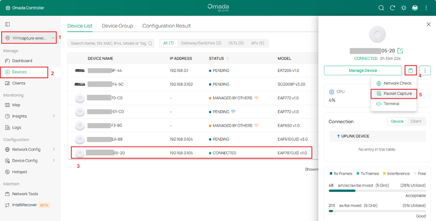
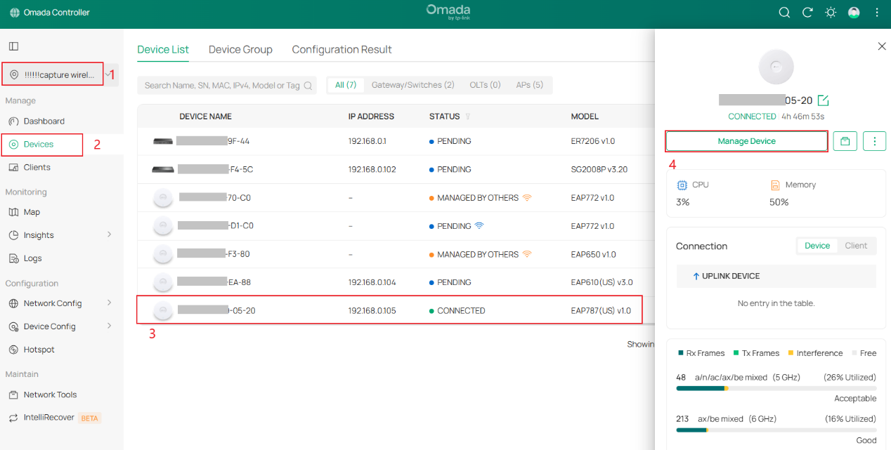
Step 1. Use the Omada Controller to adopt EAP devices and ensure that the EAP devices are in the ‘CONNECTED’ status.
Step 2. Navigate to the Packet Capture function.
There are three entry points that can be used to navigate to the packet capture function.
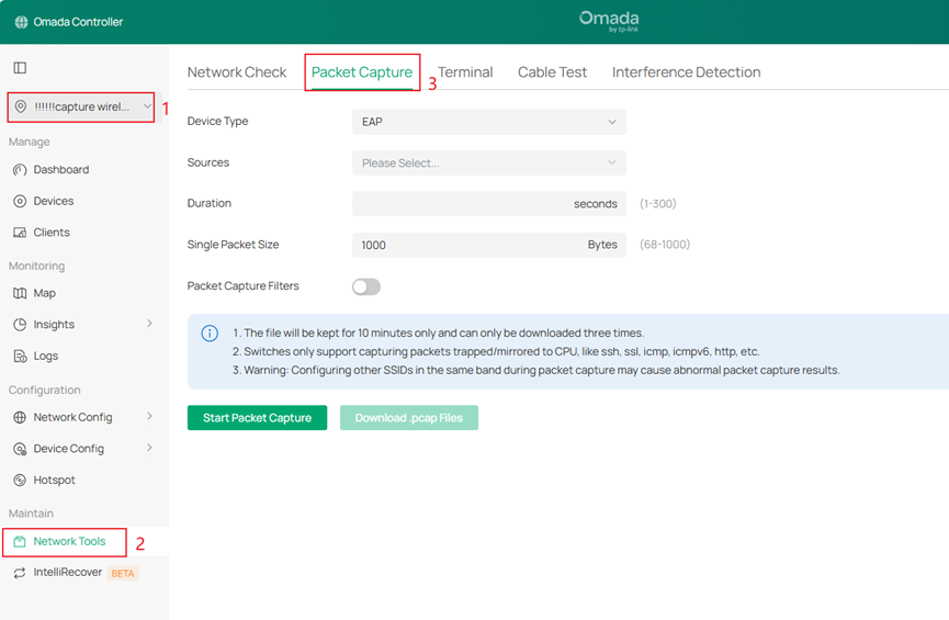
- Go to Site > Device > Packet Capture
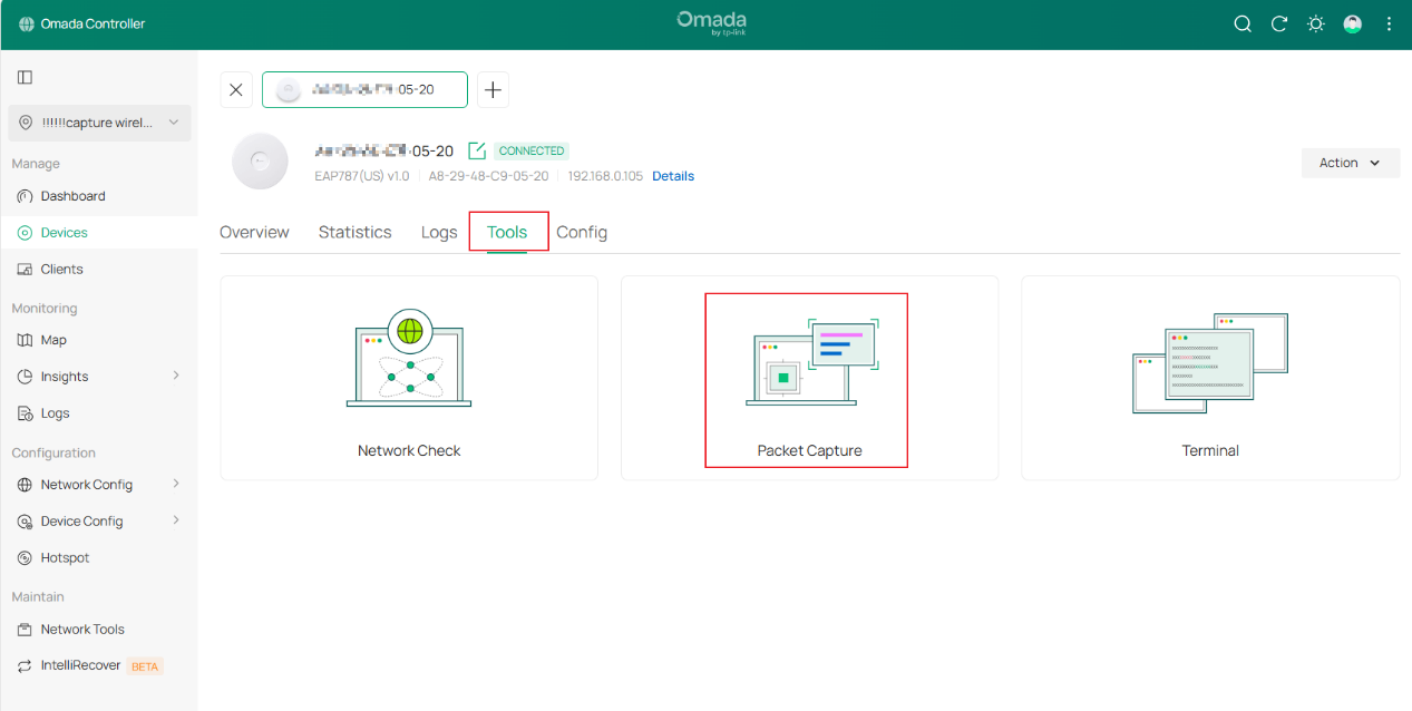
- Go to Site > Device > Manage Device > Tools > Packet Capture
Step 3. Configure the basic parameters for wireless packet capture.
- Device Type: Select the EAP device type to capture packets.
- Sources: Select one captured device to capture packets.
- Interface Type: Select wireless interface type to capture packets.
- Band: Supports 2.4 GHz/5 GHz /6 GHz.
- Channel: Only models equipped with an independent Scan-Radio chip support channel selection. (e.g., EAP787)
- SSID/Interface: Includes SSID interfaces and Mesh-related interfaces (sta interface and bkhap interface). When the band selects the 5/6 GHz, the bkhap interface must be included in the interface selection options regardless of whether it is part of a Mesh network. The sta interface is only available after successfully joining a Mesh network.
Notes: The following configurations will affect packet capturing:
1.If a certain band is turned off, packets on the SSIDs of the corresponding band will not be captured.
2.If a WLAN schedule is configured, packets outside the schedule will not be captured.
3.If a certain SSID is turned off, packets on the SSID will not be captured.
Step 4. Select Local Mode as Capture Mode.
After selecting local mode, configure the Packet Capture duration and the maximum size of a single packet. Considering the memory usage of packet capture files on local devices, the optional packet capture duration for local mode packet capture is temporarily set to 1–300 seconds.
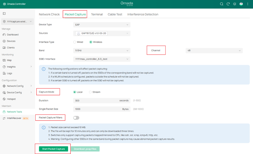
Step 5. At the same time, you can enable packet capture filters.
OTA Capture (Over-The-Air Capture): Filters applied to Wi-Fi radio frames captured directly over the air at the 802.11 MAC frame level.
Normal Capture: the packet capture filters of Non-Over-the-Air Capture
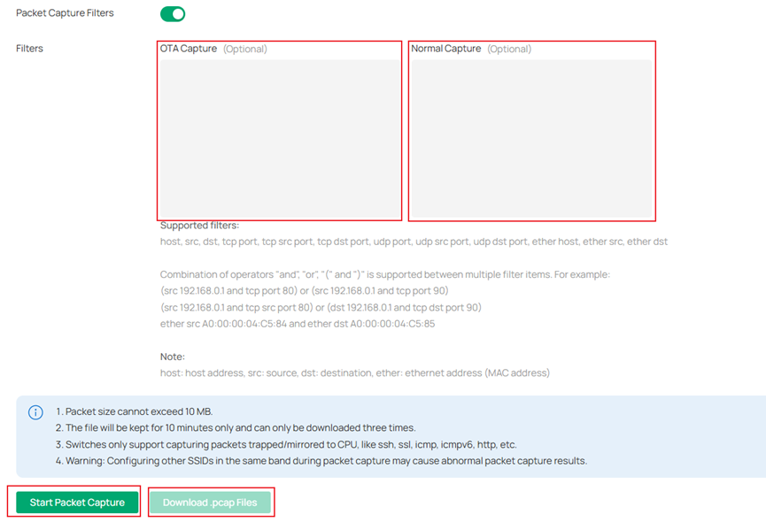
Supported filters:
host, src, dst, tcp port, tcp src port, tcp dst port, udp port, udp src port, udp dst port, ether host, ether src, ether dst
Combination of operators "and", "or", "(" and ")" is supported between multiple filter items. For example:
(src 192.168.0.1 and tcp port 80) or (src 192.168.0.1 and tcp port 90)
(src 192.168.0.1 and tcp src port 80) or (dst 192.168.0.1 and tcp dst port 90)
ether src A0:00:00:04:C5:84 and ether dst A0:00:00:04:C5:85
Note:
host: host address, src: source, dst: destination, ether: ethernet address (MAC address)
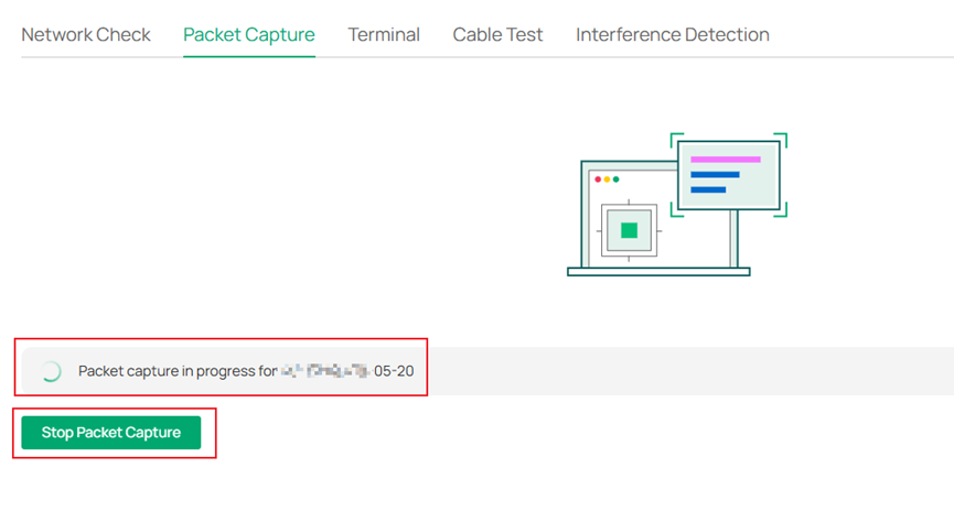
Step 6. Click Start Packet Capture, you can see Packet capture in progress for device.

Step 7. Finish Packet Capture and Click ‘Download .pcap files’ to down the packets file. Captured packets are packaged into a .pcap file and stored in the internal directory of the prototype device. They can be downloaded via the Controller Web page, with the downloaded file format being .tgz.


Notes:
1. Packet size for Wi-Fi 6 models shall not exceed 1MB, and for Wi-Fi 7 models shall not exceed 10MB.
2. The file will be kept for 10 minutes only and can only be downloaded three times.
Scenario 2: Stream Mode
Stream Mode differs from local mode packet capture in that it allows real-time display of packets captured by the AP device's wireless interface using packet capture tools such as Wireshark, facilitating on-site technical personnel in analyzing packets and identifying issues.
Before beginning packet capture using the stream mode, connect the PC where you installed Wireshark software and the AP device to be captured to the same network topology as shown in the following diagram.

Steps 1 - 3 are the same as the local mode configuration.
Step 4. Select Stream Mode as Capture Mode.
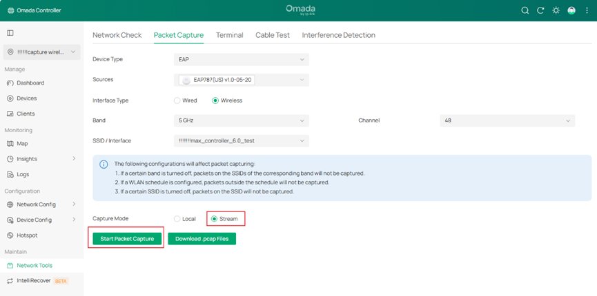
Step 5. Click ‘Start Packet Capture’. You can see Packet capture in progress for device.
Step 6. Open the Wireshark Software.
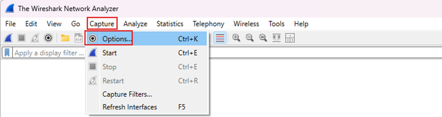
Step 7. Go to Capture > Options.
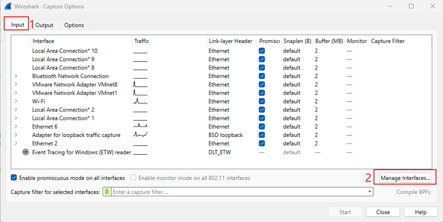
Step 8. Pop up the Capture Options page. Go to Input > Manage Interfaces.
Step 9. Pop up the Manage Interfaces page. Go to Remote Interfaces. Click ‘+’ to add a remote interface.
Host: Enter the IP address of the EAP device for packet capture.
Port: Optional.
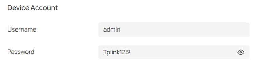
Password authentication: Enter the username and password for the EAP device, which must match the username and password of the Device Account on the Omada Controller(Go to Sites > Network Config > General Settings > Site Settings > Device Account).
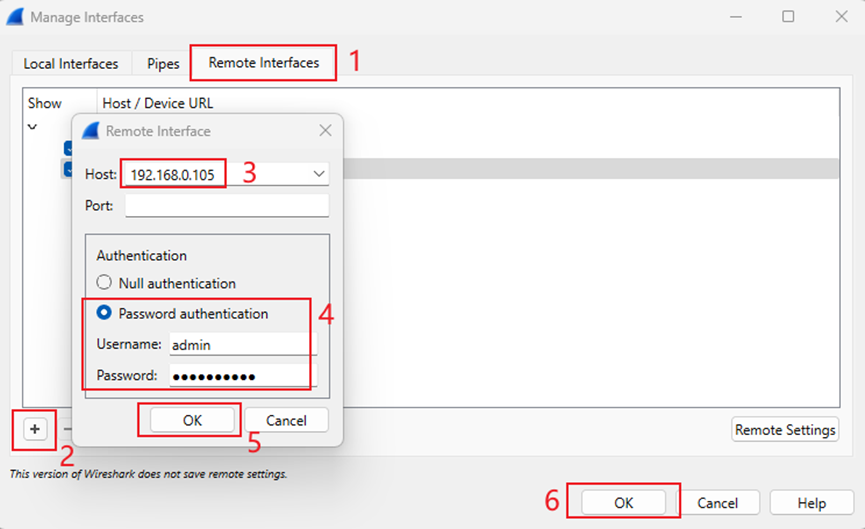
Then click ‘OK’ to save the remote interface.
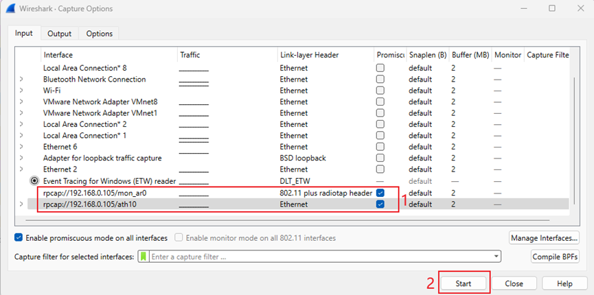
Step 10. When you see rpcap://IP address/mon x and rpcap://IP address/ath x, it indicates that the remote packet capture interface has been successfully added. Click ‘Start’ to begin packet capture.
Conclusion
By following the steps above, you have successfully Capture Wireless Packets via EAP and Omada Controller.
QA
Q1:What are the differences between the wireless packet capture supported by the Omada controller V6.0 and previous versions?
A1:
- Omada Controller V6.0 supports OTA Capture and Normal wireless packet Capture, while previous versions do not support OTA Capture.
- Omada Controller V6.0 supports Stream Mode and Local Mode. while previous versions just support Local Mode.
- For models with the Scan-Radio chip (i.e. EAP787), enable OTA Capture based on the Scan-Radio chip.
Q2:What is OTA Capture? What is the difference between OTA Capture and Normal Capture?
A2:
OTA Capture (Over-The-Air Capture): The wireless interface of the EAP is set to Monitor mode, listening to and capturing air interface packets in the air. The captured packets are all 802.11 protocol frames detected by the interface.
It is very important for us to analyze the connection process between the AP and client (includes the process of association, authentication, DE authentication, etc.) and troubleshoot issues such as packet loss, weak signal, and roaming failures., etc.
Normal Capture: The wireless interface is set to non-Monitor mode, i.e., Master mode. The kernel encapsulates 802.11 frames into standard network frames and passes them to upper-layer applications. The captured packets are those that have passed through the AP's wireless interface and are protocol stack packets.
|
Capture Mode |
Wireless Interface Mode |
Frame Type Captured |
Typical Use Case |
|
OTA Capture |
Monitor |
802.11 MAC frames |
Troubleshoot association/authentication issues |
|
Normal Capture |
Master |
Protocol stack frames |
Analyze traffic passing through the AP |
Q3: What is the difference between Scan-Radio chip models and ordinary models when using wireless packet capture?
A3:
- AP devices equipped with Scan-Radio chips can ensure that packet capture and RF scanning in the background will not affect the business functions of other clients.
- When the wireless interface of ordinary models is set to monitor mode for packet capture, it will cause the wireless clients connected to the packet capture interface of the packet capture EAP device(just MTK chip model, EAP615-Wall v1, EAP 613v1,EAP610v3,EAP650-Wall v2 etc.) to disconnect, but it will not affect non-packet capture devices and clients connected to non-packet capture SSIDs.
Note: Currently, only the EAP787 has a Scan-Radio chip; For which ordinary models are MTK chip models, please refer to the datasheet for details.
Get to know more details of each function and configuration please go to Download Center to download the manual of your product.
Is this faq useful?
Your feedback helps improve this site.

TP-Link Community
Still need help? Search for answers, ask questions, and get help from TP-Link experts and other users around the world.