


How to Configure VRF on Omada S6500 and S7500 series Switches
Contents
Introduction
VRF is short for Virtual Routing and Forwarding. By configuring VRF, we can create multiple VRF instances (also known as VPN instances) on a single router or layer three switch. Each instance has its separate routing table, allowing the same physical device to be split into multiple virtual devices that handle IP forwarding independently. This means the entries within different VRF instance routing tables will be completely independent and not related to each other. By creating interfaces and assigning them to different VRF instances, we can utilize the same IP address and subnet address for multiple interfaces and networks on the same VRF device. This significantly improves network efficiency and resiliency in response to the growing demands for campus networks.
Currently, VRF is only supported on Omada Pro L3 switches, and it is limited to a single device. This means that different VRF instances created will only separate the network on this single device; the VRF information will not be transmitted to other connected devices. VRF on Omada Pro L3 switches supports both IPv4 and IPv6 networks. This can be configured by adding an IPv4 or IPv6 address family to a VRF instance after it has been created.
Requirements
- Omada S6500 and S7500 series Switches
Configuration
In the following part, we will give a simple example of how to configure VRF based on this topology:
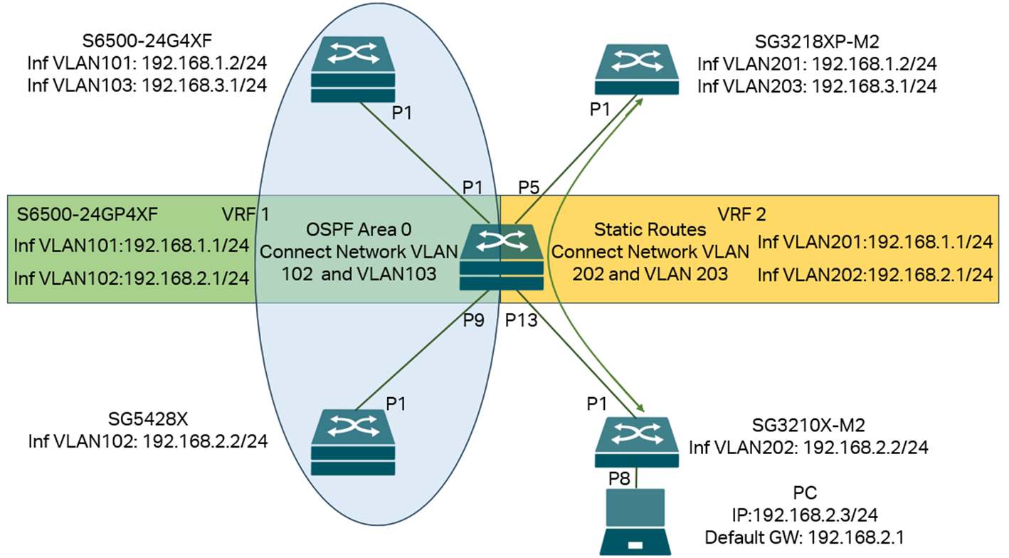
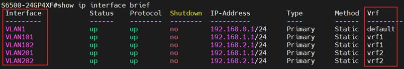
In this network, we create two VRF instances on the VRF device (S6500-24GP4XF) in the middle of the topology, VRF1 and VRF2, create four VLANs with their interfaces: 101, 102, 201, 202, for both VLAN 101 and 201, the IP addresses and subnets are the same: 192.168.1.1/24, for both VLAN 102 and 202, the IP addresses and subnets are the same: 192.168.2.1/24. The interfaces VLAN 101 and 102 will be joined in VRF1, and interfaces VLAN 201 and 202 will be joined in VRF2. This allows them to use the same IP address and subnet address on the same switch.
The two interfaces, VLAN 101 and 102 on S6500-24GP4XF, belong to VRF1 and will connect to S6500-24G4XF and SG5428X. By default, there is no route between network VLAN 102 on SG5428X and network VLAN 103 on S6500-24G4XF. To solve this, we enable OSPF on SG5428X, S6500-24G4XF, and VRF1 of S6500-24GP4XF. This enables the establishment of routes between VLAN 101, 102, and 103 networks via OSPF, allowing communication between VLAN 103 on S6500-24G4XF and VLAN 102 on SG5428X.
The two interfaces, VLAN 201 and 202 on S6500-24GP4XF, belong to VRF2 and will connect to SG3218XP-M2 and SG3210X-M2. By default, there is no route between network VLAN 202 on SG3210X-M2 and network VLAN 203 on SG3218XP-M2. To solve this, we configure static routes on SG3218XP-M2 and the VRF2 of S6500-24GP4XF, so the routes between network VLANs 202 and 203 can be established. We then configure port eight on the SG3210X-M2 as an access port for VLAN 202 and connect a PC to it. We configure the PC’s IP address to 192.168.2.3/24, which falls within VLAN 202's network, and set the default gateway to 192.168.2.1, the interface of VLAN 202 on VRF2 of the S6500-24GP4XF. After this, we should be able to communicate between the network VLAN 203 on SG3218XP-M2 and the PC.
We need to create VLANs on all devices. On S6500-24GP4XF, create the VRF instances. Next, create the necessary interfaces and assign them to the appropriate VRF instances. Then, configure the IP addresses for these interfaces. On all other switches, make the interfaces accordingly and configure IP addresses for them. After configuring the port VLAN status on all switches, all interfaces should be up and running. We then enable OSPF and static routes as mentioned above, so the connectivity will be fully established while keeping the topology as two separate parts.
Step 1. Connect the cables as shown in the topology.
Step 2. Create the VLANs on all switches according to the topology. Commands as follows:
On S6500-24GP4XF:
vlan 101-102,201-202
exit
On S6500-24G4XF:
vlan 101,103
exit
On SG5428X:
vlan 102
exit
On SG3218XP-M2:
vlan 201,203
exit
On SG3210X-M2:
vlan 202
exit
Step 3. Create two VRF instances named vrf1 and vrf2 on the VRF device (S6500-24GP4XF) and configure the address family. Commands as follows:
vrf vrf1
address-family ipv4
exit-address-family
exit
vrf vrf2
address-family ipv4
exit-address-family
exit
Step 4. Create VLAN interfaces on the VRF device (S6500-24GP4XF) and assign them to different VRF instances according to the topology, then configure their IP addresses. Commands as follows:
interface vlan 101
vrf forwarding vrf1
ip address 192.168.1.1 255.255.255.0
exit
interface vlan 102
vrf forwarding vrf1
ip address 192.168.2.1 255.255.255.0
exit
interface vlan 201
vrf forwarding vrf2
ip address 192.168.1.1 255.255.255.0
exit
interface vlan 202
vrf forwarding vrf2
ip address 192.168.2.1 255.255.255.0
exit
Step 5. Create VLAN interfaces on other switches and configure the IP addresses. Commands as follows:
On S6500-24G4XF:
interface vlan 101
ip address 192.168.1.2 255.255.255.0
exit
interface vlan 103
ip address 192.168.3.1 255.255.255.0
exit
On SG5428X:
interface vlan 102
ip address 192.168.2.2 255.255.255.0
exit
On SG3218XP-M2:
interface vlan 201
ip address 192.168.1.2 255.255.255.0
exit
interface vlan 203
ip address 192.168.3.1 255.255.255.0
exit
On SG3210X-M2:
interface vlan 202
ip address 192.168.2.2 255.255.255.0
exit
Step 6. Configure the port VLAN status and bring all the interfaces up correctly, for ports connecting to switches, join the ports tagged into the VLANs, for the port connecting to a PC, enter the port untagged into the VLAN to make it an access port for this VLAN. The PC could communicate in the correct VLAN network. Commands as follows:
On S6500-24GP4XF:
interface gigabitEthernet 1/0/1
switchport general allowed vlan 101 tagged
exit
interface gigabitEthernet 1/0/5
switchport general allowed vlan 201 tagged
exit
interface gigabitEthernet 1/0/9
switchport general allowed vlan 102 tagged
exit
interface gigabitEthernet 1/0/13
switchport general allowed vlan 202 tagged
exit
On S6500-24G4XF:
interface gigabitEthernet 1/0/1
switchport general allowed vlan 101,103 tagged
exit
On SG5428X:
interface gigabitEthernet 1/0/1
switchport general allowed vlan 102 tagged
exit
On SG3218XP-M2:
interface two-gigabitEthernet 1/0/1
switchport general allowed vlan 201,203 tagged
exit
On SG3210X-M2:
interface two-gigabitEthernet 1/0/1
switchport general allowed vlan 202 tagged
exit
interface two-gigabitEthernet 1/0/8
switchport general allowed vlan 202 untagged
switchport pvid 202
no switchport general allowed vlan 1
Step 7. Enable OSPF on the S6500-24G4XF, SG5428X, and VRF1 of the S6500-24GP4XF. We will configure all networks in area 0, whose area ID is 0.0.0.0. Create the OSPF process on each device, specify the networks and area ID to add to the process. Commands as follows:
On S6500-24G4XF:
router ospf 1
network 192.168.1.0 255.255.255.0 area 0.0.0.0
network 192.168.3.0 255.255.255.0 area 0.0.0.0
exit
On SG5428X:
router ospf 1
network 192.168.2.0 255.255.255.0 area 0.0.0.0
exit
On S6500-24GP4XF:
router ospf 1 vrf vrf1
network 192.168.1.0 255.255.255.0 area 0.0.0.0
network 192.168.2.0 255.255.255.0 area 0.0.0.0
exit
Step 7. Configure a pair of static routes between SG3218XP-M2 and VRF2 of S6500-24GP4XF to establish the routes between network VLANs 202 and 203. Commands as follows:
On S6500-24GP4XF:
ip route vrf vrf2 192.168.3.0 255.255.255.0 nexthop-vrf vrf2 192.168.1.2
On SG3218XP-M2:
ip route 192.168.2.0 255.255.255.0 192.168.1.1
We have completed the VRF configuration based on the provided example topology. This setup includes multiple VLAN interfaces and networks that share the same IP address and subnet address without causing any conflicts within the topology. Also, VRFs can carry static and dynamic routings across the network, so the networks in the same VRF instance can communicate with each other via IP routes. Still, they will not be able to communicate with networks in different VRF instances due to the independent routing tables.
Verification
After finishing the configuration, we should be able to ping the interface VLAN 103 on S6500-24G4XF from SG5428X and also ping the interface VLAN 203 on SG3218XP-M2 from the PC connecting to SG3210X-M2.
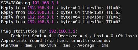
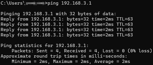
As we have introduced, the VRF instances will operate independent routing tables. We could use the command “show ip route vrf <vrf-name>” to check the different routing tables on a single device.
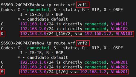
As we can see here, each VRF instance has its routing table, despite the VLAN and interface being different; the IP addresses and subnets are the same.
For the third route in each routing table, although the destination network and next hop are the same, the type codes are different. In the routing table of VRF1, it is marked as “O”, indicating that this route is formed by OSPF; in the routing table of VRF2, it is marked as “S”, indicating that this route is a static route manually created.
These results are expected from the example topology and configuration, indicating the VRF is operating without a problem, and we could also configure other features in different VRF instances.
Conclusion
In this article, we briefly introduce VRF and provide an example of configuring VRF to separate networks on a single device using a simple topology.
Get to know more details of each function and configuration please go to Download Center to download the manual of your product.
QA
Q1: What will happen if I don’t assign an interface to any created VRF instance?
A1: This interface will be kept in the default VRF, which is also separate from any other VRF instance created. You could check the interface and VRF status using the command “show ip interface brief”.
Is this faq useful?
Your feedback helps improve this site.
TP-Link Community
Still need help? Search for answers, ask questions, and get help from TP-Link experts and other users around the world.