Key Points of Managing the Switch via SNMP
CHAPTERS
Appendix. Frequently Asked Questions (FAQs)
|
|
This guide applies to: T1500G-8T v2 or above, T1500G-10PS v2 or above, T1500G-10MPS v2 or above, T1500-28PCT v3 or above, T1600G-18TS v2 or above, T1600G-28TS v3 or above, T1600G-28PS v3 or above, T1600G-52TS v3 or above, T1600G-52PS v3 or above, T1700X-16TS v3 or above, T1700G-28TQ v3 or above, T2500G-10TS v2 or above, T2600G-18TS v2 or above, T2600G-28TS v3 or above, T2600G-28MPS v3 or above, T2600G-28SQ v1 or above, T2600G-52TS v3 or above. |

TP-Link Managed Switches and Smart Switches support SNMP (Simple Network Management Protocol) and can be centrally managed by NMS (Network Management System) applications. When managing TP-Link switches via an NMS application like Net-SNMP or iReasoning MIB browser, there are some points you should pay attention to. This guide demonstrates the points through a configuration example of a company.
|
|
Note: The private MIBs may vary depending on the model and software version. In this guide, we take T2600G-28TS_v4_ 20181105 as an example. |

Figure 1-1 shows the network topology of a company’s marketing department.
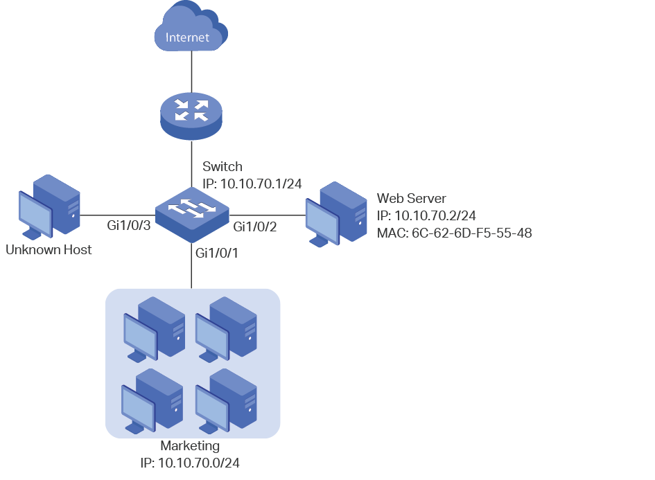
The marketing department maintains a web server which provides web services of the company’s official website. Hosts in the marketing department are connected to the switch via port 1/0/1, and the web server is connected to the switch via port 1/0/2. Hosts in the marketing department and the web server are all in VLAN 10.
Recently, the marketing department encounters some network problems. And to enhance the network performance and security, the manager of the marketing department submits a list of requirements to the network administrator:
The web server is inaccessible these days, the network administrator wants to check whether there is anything wrong with the cable.
As the web server is frequently visited, to enhance the forwarding efficiency of the switch, the web server’s MAC address should not age.
To enhance security, it is required that only the web server can access the network via port 1/0/2, while other unknown hosts, for example, the Unknown Host in Figure 1-1, will be blocked when trying to access the network via ports 1/0/2-3. Otherwise, hackers may use the IP and MAC address of the web server to intercept messages meant for the web server.
Besides the interior communications, the marketing department can only access the web server on the intranet, and can only visit http and https websites on the internet.
To meet the first requirement, you can check the cable status by the Cable Test feature. Cable testing helps you to troubleshoot based on the connection status, cable length, and the fault location.
To meet the second requirement, you can configure the MAC address of the web server as a static MAC address, and bind it to port 1/0/2 on the switch.
To meet the third requirement, you can add an IMPB entry for the web server, and enable IP Source Guard on ports 1/0/2-3.
To meet the fourth requirement, you can set up packet filtering by creating an IP ACL and configuring rules for it.
Demonstrated with SNMPv1, the following section shows how to implement the configurations via the NMS application Net-SNMP. However, the user guidelines mentioned below apply to all NMS applications.
To obtain the properties of an object, such as the object name, OID, and the index, you can use a MIB browser like iReasoning MIB Browser. A MIB browser gives a visual interface to view the MIBs.
To configure the switch via SNMPv1, you need to enable SNMP and create a Read & Write community first. Follow the instructions below to enable SNMP, and create a community with the name “snmpgroup” by CLI. For more details about configuring SNMP, see Configuring SNMP & RMON.
Switch#configure
Switch(config)#snmp-server
Switch(config)#snmp-server community snmpgroup read-write
Switch(config)#show snmp-server
SNMP agent is enabled.
5634 SNMP packets input
...
Switch(config)#show snmp-server community
Index Name Type MIB-View
------- ---------- -------- --------------
1 snmpgroup read-write viewDefault
3.1Testing the Cable that is Connecting the Web Server and the Switch
User Guidelines
The switch supports two different SNMP objects for cable test. You can choose one according to your needs.
To test the link-down ports only: we recommend you use the object “tpPortCableTestTable”. When testing cables via the object “tpPortCableTestTable”, pay attention to the following points:
To test the cable and check the results, you can directly retrieve values from the object “tpPortCableTestEntry“. When you read the object, the switch will automatically test the cable and returns the test results.
The switch will perform cable testing only on the link-down ports and skip the link-up ports.
Choose a port to test, and convert the port number into a numeric code according to the rules described in Q1 Why Does it Fail When I Try to Retrieve Values of a Port?. For T2600G-28TS, when the port number acts as an index of the object, it should be converted into a numeric code “49152+Port ID”. Then use the numeric code as the index of the object “tpPortCableTestEntry“.
For how to obtain the index information of an object, refer to Q3 How Do I Know the Index When Retrieving the Value from within a Table?
To test both the link-down and link-up ports: use the object “tpPortCableTestCFTable”. When testing cables via the object “tpPortCableTestCFTable”, pay attention to the following points:
You need to start cable test by setting a value for the object “tpPortCableTestFlush” first, and then the switch will fill the object “tpPortCableTestCFEntry” with the test results, and you can check the results for each pair. If you retrieve the value of the object “tpPortCableTestCFEntry” without testing, the switch returns the last cable testing result.
Testing cables via this object, the switch will perform the test on all the specified ports, no matter they are down or up.
Do not test the cable connecting the switch and the PC which you are using to manage the switch. To start cable test, the switch needs to cut off its connection with the target devices for a while. If you test the cable that is connecting to your using PC, the PC cannot receive the test results, and the system will display a timeout error.
Remember the index of the object “tpPortCableTestFlush”. It is a scalar object, and the index for scalar objects are always a simple .0 (zero). For more details, refer to Q2 Why Does it Fail When I Try to Retrieve the Value of a Scalar Object?
The index of the object “tpPortCableTestCFEntry” is also the port number of which you want to test. You need to use a numeric code “49152+Port ID” to indicate the port number, which is similar to the object “tpPortCableTestTable”.
Configuration Steps
The following sections provide how to test the cable that is connecting the web server and the switch in two ways: using the object “tpPortCableTestTable” and using the object “tpPortCableTestCFTable”.
Using the Object “tpPortCableTestTable”
1)Convert the port number into the numeric code. The numeric code for port 1/0/2 is 49154 (49152+2).
2)Read values from the object “tpPortCableTestEntry”. You can perform either snmpget or snmpwalk action. Here we perform snmpget action to only get the cable information of port 1/0/2. Note that we use 49154 to indicate port 1/0/2.
|
C:\Users\Administrator>snmpget -v 1 -c snmpgroup 10.10.70.1 1.3.6.1.4.1.11863.6.8.1.2.1.2.49154 1.3.6.1.4.1.11863.6.8.1.2.1.3.49154 1.3.6.1.4.1.11863.6.8.1.2.1.4.49154 1.3.6.1.4.1.11863.6.8.1.2.1.5.49154 1.3.6.1.4.1.11863.6.8.1.2.1.6.49154 1.3.6.1.4.1.11863.6.8.1.2.1.7.49154 1.3.6.1.4.1.11863.6.8.1.2.1.8.49154 1.3.6.1.4.1.11863.6.8.1.2.1.9.49154 SNMPv2-SMI::enterprises.11863.6.8.1.2.1.2.49154 = STRING: “Open” //Status of pair A. SNMPv2-SMI::enterprises.11863.6.8.1.2.1.3.49154 = STRING: “25 (+/- 10m)” //Length of pair A. SNMPv2-SMI::enterprises.11863.6.8.1.2.1.4.49154 = STRING: “Open” //Status of pair B. SNMPv2-SMI::enterprises.11863.6.8.1.2.1.5.49154 = STRING: “25 (+/- 10m)” //Length of pair B. SNMPv2-SMI::enterprises.11863.6.8.1.2.1.6.49154 = STRING: “Open” //Status of pair C. SNMPv2-SMI::enterprises.11863.6.8.1.2.1.7.49154 = STRING: “25 (+/- 10m)” //Length of pair C. SNMPv2-SMI::enterprises.11863.6.8.1.2.1.8.49154 = STRING: “Open” //Status of pair D. SNMPv2-SMI::enterprises.11863.6.8.1.2.1.9.49154 = STRING: “25 (+/- 10m)” //Length of pair D. |
In this case, the cable status is Open, which means the connection is broken. Make sure the two ends of the cable are both plugged into the Ethernet port tightly.
Using the Object “tpPortCableTestCFTable”
1)Start the cable test on port 1/0/2. Remember to add the index .0 for the object “tpPortCableTestFlush”.
|
C:\Users\Administrator>snmpset -v 1 -c snmpgroup 10.10.70.1 1.3.6.1.4.1.11863.6.8.1.3.1.0 s 1/0/2 SNMPv2-SMI::enterprises.11863.6.8.1.3.1.0 = STRING: “1/0/2” |
2)Convert the port number into the numeric code. The numeric code for port 1/0/2 is 49154 (49152+2).
3)Check the result by reading values from the object “tpPortCableTestCFEntry“. Note that we use 49154 to indicate port 1/0/2.
|
C:\Users\Administrator>snmpget -v 1 -c snmpgroup 10.10.70.1 1.3.6.1.4.1.11863.6.8.1.3.2.2.49154 1.3.6.1.4.1.11863.6.8.1.3.2.3.49154 1.3.6.1.4.1.11863.6.8.1.3.2.4.49154 1.3.6.1.4.1.11863.6.8.1.3.2.5.49154 1.3.6.1.4.1.11863.6.8.1.3.2.6.49154 1.3.6.1.4.1.11863.6.8.1.3.2.7.49154 1.3.6.1.4.1.11863.6.8.1.3.2.8.49154 1.3.6.1.4.1.11863.6.8.1.3.2.9.49154 SNMPv2-SMI::enterprises.11863.6.8.1.3.2.2.49154 = STRING: “Open” //Status of pair A. SNMPv2-SMI::enterprises.11863.6.8.1.3.2.3.49154 = STRING: “25 (+/- 10m)” //Length of pair A. SNMPv2-SMI::enterprises.11863.6.8.1.3.2.4.49154 = STRING: “Open” //Status of pair B. SNMPv2-SMI::enterprises.11863.6.8.1.3.2.5.49154 = STRING: “25 (+/- 10m)” //Length of pair B. SNMPv2-SMI::enterprises.11863.6.8.1.3.2.6.49154 = STRING: “Open” //Status of pair C. SNMPv2-SMI::enterprises.11863.6.8.1.3.2.7.49154 = STRING: “25 (+/- 10m)” //Length of pair C. SNMPv2-SMI::enterprises.11863.6.8.1.3.2.8.49154 = STRING: “Open” //Status of pair D. SNMPv2-SMI::enterprises.11863.6.8.1.3.2.9.49154 = STRING: “25 (+/- 10m)” //Length of pair D. |
In this case, the cable status is Open, which means the connection is broken. Make sure the two ends of the cable are both plugged into the Ethernet port tightly.
3.2Adding a Static MAC Address Entry for the Web Server
User Guidelines
To add a static MAC address entry via SNMP, pay attention to the following points:
Convert the MAC address into dotted-decimal notation first, and then use the dotted-decimal-notation MAC address combined with the VLAN ID as the index of the static MAC address entries.
Set values for the objects “tpl2BridgeManageStaticStatus” and “tpl2BridgeManageStaticPort” in one command. Besides the MAC address and the VLAN ID (the indexes), the port number is also mandatory to create a static MAC address entry, so you need to set the value of the object “tpl2BridgeManageStaticPort” together with the object “tpl2BridgeManageStaticStatus”.
Configuration Steps
Follow the steps below to add the static MAC address entry for the web server:
1)Convert the MAC address into dotted-decimal notation. The dotted-decimal notation of 6C-62-6D-F5-55-48 is 108.98.109.245.85.72. We use .108.98.109.245.85.72.10 (.MAC_address.VLAN_ID) as the index of the entry.
2)Add the entry.
|
C:\Users\Administrator>snmpset -v 1 -c snmpgroup 10.10.70.1 1.3.6.1.4.1.11863.6.10.1.1.1.1.3.108.98.109.245.85.72.10 s 1/0/2 1.3.6.1.4.1.11863.6.10.1.1.1.1.4.108.98.109.245.85.72.10 i 4 //Add a static MAC address entry with the MAC address 6C-62-6D-F5-55-48 (108.98.109.245.85.72), the VLAN ID 10, and the port number 1/0/2. SNMPv2-SMI::enterprises.11863.6.10.1.1.1.1.3.108.98.109.245.85.72.10 = STRING: “1/0/2” SNMPv2-SMI::enterprises.11863.6.10.1.1.1.1.4.108.98.109.245.85.72.10 = INTEGER: 4 // Create the static MAC address entry. |
3)Verify the configurations.
|
C:\Users\Administrator>snmpget -v 1 -c snmpgroup 10.10.70.1 1.3.6.1.4.1.11863.6.10.1.1.1.1.1.108.98.109.245.85.72.10 1.3.6.1.4.1.11863.6.10.1.1.1.1.2.108.98.109.245.85.72.10 1.3.6.1.4.1.11863.6.10.1.1.1.1.3.108.98.109.245.85.72.10 //Get the detail information of the static MAC address entry whose index is .108.98.109.245.85.72.10. SNMPv2-SMI::enterprises.11863.6.10.1.1.1.1.1.108.98.109.245.85.72.10 = STRING: “6c-62-6d-f5-55-48” //The MAC address. SNMPv2-SMI::enterprises.11863.6.10.1.1.1.1.2.108.98.109.245.85.72.10 = INTEGER: 10 //The VLAN ID. SNMPv2-SMI::enterprises.11863.6.10.1.1.1.1.3.108.98.109.245.85.72.10= STRING: “1/0/2” //The port number. |
3.3Adding an IMPB Entry and Enabling the IP Source Guard
User Guidelines
To add an IMPB entry, pay attention to the following points:
When creating an IMPB entry, we need to use 0 (zero) as the index of the entry. While when retrieving an existing IMPB entry, we use the binding IP address as the index.
All the parameters including the host name, IP address, MAC address, VLAN ID, binding port, and protect type should be given in the same command, because they are all mandatory to create an IMPB entry.
Configuration Steps
Follow the steps below to add an IMPB entry for the web server and enable IP source guard on port 1/0/2-3:
1)Add the IMPB entry.
|
C:\Users\Administrator>snmpset -v 1 -c snmpgroup 10.10.70.1 1.3.6.1.4.1.11863.6.68.1.1.1.1.1.0 s user1 1.3.6.1.4.1.11863.6.68.1.1.1.1.2.0 a 10.10.70.2 1.3.6.1.4.1.11863.6.68.1.1.1.1.3.0 s 6c-62-6d-f5-55-48 1.3.6.1.4.1.11863.6.68.1.1.1.1.4.0 i 10 1.3.6.1.4.1.11863.6.68.1.1.1.1.5.0 s 1/0/2 1.3.6.1.4.1.11863.6.68.1.1.1.1.6.0 i 2 1.3.6.1.4.1.11863.6.68.1.1.1.1.8.0 i 4 SNMPv2-SMI::enterprises.11863.6.68.1.1.1.1.1.0 = STRING: “user1” // The host name. SNMPv2-SMI::enterprises.11863.6.68.1.1.1.1.2.0 = IpAddress: 10.10.70.2 // The IP address. SNMPv2-SMI::enterprises.11863.6.68.1.1.1.1.3.0 = STRING: “6c-62-6d-f5-55-48” // The MAC address. SNMPv2-SMI::enterprises.11863.6.68.1.1.1.1.4.0 = INTEGER: 10 // The VLAN ID. SNMPv2-SMI::enterprises.11863.6.68.1.1.1.1.5.0 = STRING: “1/0/2” // The port ID. SNMPv2-SMI::enterprises.11863.6.68.1.1.1.1.6.0 = INTEGER: 2 // The protect type. 2 indicates IP Source Guard. SNMPv2-SMI::enterprises.11863.6.68.1.1.1.1.8.0 = INTEGER: 4 // Create the IMPB entry. |
2)Enable IP source guard on ports 1/0/2-3:
|
C:\Users\Administrator>snmpset -v 1 -c snmpgroup 10.10.70.1 1.3.6.1.4.1.11863.6.29.1.1.2.1.2.49154 i 2 1.3.6.1.4.1.11863.6.29.1.1.2.1.2.49155 i 2 SNMPv2-SMI::enterprises.11863.6.29.1.1.2.1.2.49154 = INTEGER: 2 // IP source guard is enabled on port 1/0/2. SNMPv2-SMI::enterprises.11863.6.29.1.1.2.1.2.49155 = INTEGER: 2 // IP source guard is enabled on port 1/0/3. |
3.4Adding an IP ACL and Configuring Rules for it
User Guidelines
To create an ACL via SNMP, pay attention to the following points:
Firstly, determine the ACL ID according to the type of the ACL, and assign a rule ID for the rule. We use the ACL ID combined with the rule ID as the index of the ACL objects.
Create the ACL and the rule entries before configuring the detailed rules for the ACL. The ACL and rule entries can be created simultaneously by setting the value of the object “tpXXRuleStatus” as integer 4. Here “XX“ represents the type of the ACL, like MAC, IP, Combined, and so on.
To bind the ACL to a port, set values for the objects “tpAclPortBindStatus“ and “tpAclBindPortList“ in one command. The index of the binding entry is the ACL ID, but the port number is also a mandatory parameter to create a binding entry, so we need to set values for the two objects simultaneously.
Configuration Steps
Follow the steps below to add an IP ACL entry and configure rules for it:
1)Create the IP ACL entry and a rule entry. For T2600G-28TS, IP ACL ID ranges from 500 to 999. You can create an IP ACL with the ACL ID 500, and the first rule ID 1.
|
C:\Users\Administrator>snmpset -c snmpgroup -v 1 10.10.70.1 1.3.6.1.4.1.11863.6.26.1.1.2.1.21.500.1 i 4 // Create the ACL 500 and Rule 1. SNMPv2-SMI::enterprises.11863.6.26.1.1.2.1.21.500.1 = INTEGER: 4 |
2)Configure Rule 1. To allow the marketing department to access the web server, configure Rule 1 as a permit rule, and match packets with source IP address 10.10.70.0/24 and destination IP address 10.10.70.2/32.
|
C:\Users\Administrator>snmpset -c snmpgroup -v 1 10.10.70.1 1.3.6.1.4.1.11863.6.26.1.1.2.1.4.500.1 i 0 // Configure the operation of Rule 1 as Permit. SNMPv2-SMI::enterprises.11863.6.26.1.1.2.1.4.500.1 = INTEGER: 0 C:\Users\Administrator>snmpset -c snmpgroup -v 1 10.10.70.1 1.3.6.1.4.1.11863.6.26.1.1.2.1.7.500.1 a 10.10.70.0 1.3.6.1.4.1.11863.6.26.1.1.2.1.8.500.1 a 255.255.255.0 //Match packets with the source IP address 10.10.70.0/24. SNMPv2-SMI::enterprises.11863.6.26.1.1.2.1.7.500.1 = IpAddress: 10.10.70.0 SNMPv2-SMI::enterprises.11863.6.26.1.1.2.1.8.500.1 = IpAddress: 255.255.255.0 C:\Users\Administrator>snmpset -c snmpgroup -v 1 10.10.70.1 1.3.6.1.4.1.11863.6.26.1.1.2.1.9.500.1 a 10.10.70.2 1.3.6.1.4.1.11863.6.26.1.1.2.1.10.500.1 a 255.255.255.255 //Match packets with the destination IP address 10.10.70.2/32 SNMPv2-SMI::enterprises.11863.6.26.1.1.2.1.9.500.1 = IpAddress: 10.10.70.2 SNMPv2-SMI::enterprises.11863.6.26.1.1.2.1.10.500.1 = IpAddress: 255.255.255.255 |
3)Create Rule 2 and Rule 3. Configure the rules to permit packets with source IP 10.10.70.0 and destination port TCP 80 (http service port) and TCP 443 (https service port).
|
C:\Users\Administrator>snmpset -c snmpgroup -v 1 10.10.70.1 1.3.6.1.4.1.11863.6.26.1.1.2.1.21.500.2 i 4 1.3.6.1.4.1.11863.6.26.1.1.2.1.21.500.3 i 4 // Create Rule 2 and Rule 3. SNMPv2-SMI::enterprises.11863.6.26.1.1.2.1.21.500.2 = INTEGER: 4 SNMPv2-SMI::enterprises.11863.6.26.1.1.2.1.21.500.3 = INTEGER: 4 C:\Users\Administrator>snmpset -c snmpgroup -v 1 10.10.70.1 1.3.6.1.4.1.11863.6.26.1.1.2.1.4.500.2 i 0 1.3.6.1.4.1.11863.6.26.1.1.2.1.4.500.3 i 0 // Configure the operation of Rule 2 and Rule 3 as Permit. SNMPv2-SMI::enterprises.11863.6.26.1.1.2.1.4.500.2 = INTEGER: 0 SNMPv2-SMI::enterprises.11863.6.26.1.1.2.1.4.500.3 = INTEGER: 0 C:\Users\Administrator>snmpset -c snmpgroup -v 1 10.10.70.1 1.3.6.1.4.1.11863.6.26.1.1.2.1.7.500.2 a 10.10.70.0 1.3.6.1.4.1.11863.6.26.1.1.2.1.8.500.2 a 255.255.255.0 1.3.6.1.4.1.11863.6.26.1.1.2.1.7.500.3 a 10.10.70.0 1.3.6.1.4.1.11863.6.26.1.1.2.1.8.500.3 a 255.255.255.0 //Match packets with the source IP address 10.10.70.0/24. SNMPv2-SMI::enterprises.11863.6.26.1.1.2.1.7.500.2 = IpAddress: 10.10.70.0 SNMPv2-SMI::enterprises.11863.6.26.1.1.2.1.8.500.2 = IpAddress: 255.255.255.0 SNMPv2-SMI::enterprises.11863.6.26.1.1.2.1.7.500.3 = IpAddress: 10.10.70.0 SNMPv2-SMI::enterprises.11863.6.26.1.1.2.1.8.500.3 = IpAddress: 255.255.255.0 C:\Users\Administrator>snmpset -c snmpgroup -v 1 10.10.70.1 1.3.6.1.4.1.11863.6.26.1.1.2.1.11.500.2 i 6 1.3.6.1.4.1.11863.6.26.1.1.2.1.15.500.2 i 80 1.3.6.1.4.1.11863.6.26.1.1.2.1.16.500.2 s ffff //Rule 2 matches packets with the destination port TCP 80, and the mask for the destination port is ffff. SNMPv2-SMI::enterprises.11863.6.26.1.1.2.1.11.500.2 = INTEGER: 6 //The IP protocol is set as TCP. SNMPv2-SMI::enterprises.11863.6.26.1.1.2.1.15.500.2 = INTEGER: 80 SNMPv2-SMI::enterprises.11863.6.26.1.1.2.1.16.500.2 = STRING: “ffff” C:\Users\Administrator>snmpset -c snmpgroup -v 1 10.10.70.1 1.3.6.1.4.1.11863.6.26.1.1.2.1.11.500.3 i 6 1.3.6.1.4.1.11863.6.26.1.1.2.1.15.500.3 i 443 1.3.6.1.4.1.11863.6.26.1.1.2.1.16.500.3 s ffff //Rule 3 matches packets with the destination port TCP 443, and the mask for the destination port is ffff. SNMPv2-SMI::enterprises.11863.6.26.1.1.2.1.11.500.3 = INTEGER: 6 SNMPv2-SMI::enterprises.11863.6.26.1.1.2.1.15.500.3 = INTEGER: 443 SNMPv2-SMI::enterprises.11863.6.26.1.1.2.1.16.500.3 = STRING: “ffff” |
4)Create Rule 4 and Rule 5. Configure the rules to permit packets with source IP 10.10.70.0 and destination port TCP 53 and UDP 53 (both are DNS service ports).
|
C:\Users\Administrator>snmpset -c snmpgroup -v 1 10.10.70.1 1.3.6.1.4.1.11863.6.26.1.1.2.1.21.500.4 i 4 1.3.6.1.4.1.11863.6.26.1.1.2.1.21.500.5 i 4 // Create Rule 4 and Rule 5. SNMPv2-SMI::enterprises.11863.6.26.1.1.2.1.21.500.4 = INTEGER: 4 SNMPv2-SMI::enterprises.11863.6.26.1.1.2.1.21.500.5 = INTEGER: 4 C:\Users\Administrator>snmpset -c snmpgroup -v 1 10.10.70.1 1.3.6.1.4.1.11863.6.26.1.1.2.1.4.500.4 i 0 1.3.6.1.4.1.11863.6.26.1.1.2.1.4.500.5 i 0 // Configure the operation of Rule 4 and Rule 5 as Permit. SNMPv2-SMI::enterprises.11863.6.26.1.1.2.1.4.500.4 = INTEGER: 0 SNMPv2-SMI::enterprises.11863.6.26.1.1.2.1.4.500.5 = INTEGER: 0 C:\Users\Administrator>snmpset -c snmpgroup -v 1 10.10.70.1 1.3.6.1.4.1.11863.6.26.1.1.2.1.7.500.4 a 10.10.70.0 1.3.6.1.4.1.11863.6.26.1.1.2.1.8.500.4 a 255.255.255.0 1.3.6.1.4.1.11863.6.26.1.1.2.1.7.500.5 a 10.10.70.0 1.3.6.1.4.1.11863.6.26.1.1.2.1.8.500.5 a 255.255.255.0 //Match packets with the source IP address 10.10.70.0/24. SNMPv2-SMI::enterprises.11863.6.26.1.1.2.1.7.500.4 = IpAddress: 10.10.70.0 SNMPv2-SMI::enterprises.11863.6.26.1.1.2.1.8.500.4 = IpAddress: 255.255.255.0 SNMPv2-SMI::enterprises.11863.6.26.1.1.2.1.7.500.5 = IpAddress: 10.10.70.0 SNMPv2-SMI::enterprises.11863.6.26.1.1.2.1.8.500.5 = IpAddress: 255.255.255.0 C:\Users\Administrator>snmpset -c snmpgroup -v 1 10.10.70.1 1.3.6.1.4.1.11863.6.26.1.1.2.1.11.500.4 i 6 1.3.6.1.4.1.11863.6.26.1.1.2.1.15.500.4 i 53 1.3.6.1.4.1.11863.6.26.1.1.2.1.16.500.4 s ffff //Rule 4 matches packets with the destination port TCP 53, and the mask for the destination port is ffff. SNMPv2-SMI::enterprises.11863.6.26.1.1.2.1.11.500.4 = INTEGER: 6 //The IP protocol is set as TCP. SNMPv2-SMI::enterprises.11863.6.26.1.1.2.1.15.500.4 = INTEGER: 53 SNMPv2-SMI::enterprises.11863.6.26.1.1.2.1.16.500.4 = STRING: “ffff” C:\Users\Administrator>snmpset -c snmpgroup -v 1 10.10.70.1 1.3.6.1.4.1.11863.6.26.1.1.2.1.11.500.5 i 17 1.3.6.1.4.1.11863.6.26.1.1.2.1.15.500.5 i 53 1.3.6.1.4.1.11863.6.26.1.1.2.1.16.500.5 s ffff //Rule 5 matches packets with the destination port UDP 53, and the mask for the destination port is ffff. SNMPv2-SMI::enterprises.11863.6.26.1.1.2.1.11.500.3 = INTEGER: 17 //The IP protocol is set as UDP. SNMPv2-SMI::enterprises.11863.6.26.1.1.2.1.15.500.3 = INTEGER: 53 SNMPv2-SMI::enterprises.11863.6.26.1.1.2.1.16.500.3 = STRING: “ffff” |
5)Create Rule 6 and configure the rule to deny packets with source IP address 10.10.70.0/24.
Packets that match Rule 1-5 will be permitted and the other will be denied according to Rule 6. Because the switch matches the packets with the rules in order, starting with Rule 1. If a packet matches a rule, the switch stops the matching process and initiates the action defined in the rule.
|
C:\Users\Administrator>snmpset -c snmpgroup -v 1 10.10.70.1 1.3.6.1.4.1.11863.6.26.1.1.2.1.21.500.6 i 4 // Create Rule 6 SNMPv2-SMI::enterprises.11863.6.26.1.1.2.1.21.500.6 = INTEGER: 4 C:\Users\Administrator>snmpset -c snmpgroup -v 1 10.10.70.1 1.3.6.1.4.1.11863.6.26.1.1.2.1.4.500.6 i 1 // Configure the operation of Rule 6 as Deny. SNMPv2-SMI::enterprises.11863.6.26.1.1.2.1.4.500.6 = INTEGER: 1 C:\Users\Administrator>snmpset -c snmpgroup -v 1 10.10.70.1 1.3.6.1.4.1.11863.6.26.1.1.2.1.7.500.6 a 10.10.70.0 1.3.6.1.4.1.11863.6.26.1.1.2.1.8.500.6 a 255.255.255.0 //Match packets with the source IP address 10.10.70.0/24. SNMPv2-SMI::enterprises.11863.6.26.1.1.2.1.7.500.6 = IpAddress: 10.10.70.0 SNMPv2-SMI::enterprises.11863.6.26.1.1.2.1.8.500.6 = IpAddress: 255.255.255.0 |
6)Bind ACL 500 to port 1/0/2 to make it take effect.
|
C:\Users\Administrator>snmpset -c snmpgroup -v 1 10.10.70.1 1.3.6.1.4.1.11863.6.26.1.4.1.1.3.500 i 4 1.3.6.1.4.1.11863.6.26.1.4.1.1.2.500 s 1/0/2 SNMPv2-SMI::enterprises.11863.6.26.1.4.1.1.3.500 = INTEGER: 4 SNMPv2-SMI::enterprises.11863.6.26.1.4.1.1.2.500 = STRING: “1/0/2” |
Appendix: Frequently Asked Questions (FAQs)
Q1Why Does it Fail When I Try to Retrieve Values of a Port?
To get or set values of a port, the port number may act as an index of the object or a parameter value of the object.
If the port number acts as an index of the object, the port number should be converted to a numeric code first. We use the numeric code as the index of the object.
The numeric code contains 2 bytes, and can indicate physical interfaces, LAG interfaces, loopback interfaces, and VLAN interfaces.
For T1700G-28TQ, calculate the numeric code according to the following rules:
| 15bits | 2bits | 5bits | 3bits | 7bits |
----------------------------------------------------------
| Reserved (0x0) | 0x3 | Unit | Slot | Port |
----------------------------------------------------------
| Reserved (0x0) | 0x2 | 0x00 | LAG ID |
----------------------------------------------------------
| Reserved (0x0) | 0x1 | 0x00 | Loopback ID |
----------------------------------------------------------
| Reserved (0x0) | 0x0 | VLAN ID |
----------------------------------------------------------
That is,
For physical interfaces, if the Unit ID is 1, then the code is “99328+Port ID” (the Slot ID is always 0).
For LAG interfaces, the code is “65536+LAG ID”.
For loopback interfaces, the code is “32768+Loopback ID”.
For VLAN interfaces, the code is exactly the VLAN ID.
For other switches, calculate the numeric code according to the following rules:
| 16bits | 2bits | 6bits | 8bits |
------------------------------------------------------------
| Reserved (0x0) | 0x3 | Unit | Port |
------------------------------------------------------------
| Reserved (0x0) | 0x2 | 0x00 | LAG ID |
------------------------------------------------------------
| Reserved (0x0) | 0x1 | 0x00 | Loopback ID |
------------------------------------------------------------
| Reserved (0x0) | 0x0 | VLAN ID |
------------------------------------------------------------
That is,
For physical interfaces, the code is “49152+Port ID” (the Unit ID is always 0).
For LAG interfaces, the code is “32768+LAG ID”.
For loopback interfaces, the code is “16384+Loopback ID”.
For VLAN interfaces, the code is exactly the VLAN ID.
Demonstrated with T2600G-28TS v4, the following example shows how to allow the switch to send a MAC address change notification when it learns a new MAC address on port 1/0/5:
|
C:\Users\Administrator>snmpset -v 1 -c snmpgroup 10.10.70.1 1.3.6.1.4.1.11863.6.10.1.5.4.1.4.49157 i 1 SNMPv2-SMI::enterprises.11863.6.10.1.5.4.1.4.49157 = INTEGER: 1 |
In this example, port 1/0/5 is the index of the object 1.3.6.1.4.1.11863.6.10.1.5.4.1.4 (tpl2BridgeManageNewMacLrn), so we convert it to the numeric code “49152+5” and use the code as the index.
If the port number acts as a parameter value of the object, the format of the port number is “Unit ID/Slot ID/Port ID”. For switches that do not support the stack feature, the Unit ID is always 1 and the Slot ID is always 0, so the port number is presented as “1/0/x”.
The following example shows how to bind ACL_500 to port 1/0/9:
|
C:\Users\Administrator>snmpset -c snmpgroup -v 1 10.10.70.1 1.3.6.1.4.1.11863.6.26.1.4.1.1.3.500 i 4 1.3.6.1.4.1.11863.6.26.1.4.1.1.2.500 s 1/0/9 SNMPv2-SMI::enterprises.11863.6.26.1.4.1.1.3.500 = INTEGER: 4 SNMPv2-SMI::enterprises.11863.6.26.1.4.1.1.2.500 = STRING: “1/0/9” |
In this example, port 1/0/9 is the value of the object 1.3.6.1.4.1.11863.6.26.1.4.1.1.2.500, so we use the format “1/0/9”.
|
|
Note: PoE Feature is an exception. For PoE, no matter the port number acts as parameter value or index, we use the port ID to present the port number. For example, we use 1 to represent port 1/0/1. |
Q2Why Does it Fail When I Try to Retrieve the Value of a Scalar Object?
Check if you have forgotten the index of the data being requested. A common mistake when retrieving or setting the value of a scalar object is to forget the index of the data.
This is less likely when retrieving a value from within a table, where it is natural to include the index as part of the OID. But for scalar objects, there is only one value, so it doesn’t seem necessary to specify an index. However, SNMP is consistent in requiring an instance for all MIB objects - even scalar objects. In this case, the instance sub-identifier is always a simple .0 (zero).
The following example shows how to start cable test for port 1/0/23:
|
C:\Users\Administrator>snmpset -v 1 -c snmpgroup 10.10.70.1 1.3.6.1.4.1.11863.6.8.1.3.1.0 s 1/0/23 SNMPv2-SMI::enterprises.11863.6.8.1.3.1.0 = STRING: “1/0/23” |
In this example, the OID of the object “tpPortCableTestFlush” is 1.3.6.1.4.1.11863.6.8.1.3.1, but we need to add an index .0 to request this object.
Q3How Do I Know the Index When Retrieving the Value from within a Table?
To get the properties of an object, such as the object name, OID, and the index, we recommend you to use a MIB browser. A MIB browser gives a visual interface to manage SNMP enabled devices.
Here we take iReasoning MIB Browser as an example to illustrate how to get the index information.
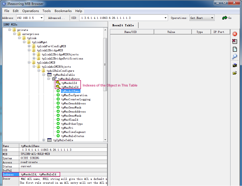
There are two methods to obtain the index information:
Tell the indexes from the objects that are labeled with the key icon  . The indexes are also sub-objects of the table. They are labeled with the key icon .
When an object is selected, you can directly view the index information from the left bottom of the window.
In the above figure, indexes for the object tpMacRuleEntry and its sub-objects are (tpMacAclId, tpMacRuleId). That is, when retrieving the ACL name, you need to specify the ACL ID and Rule ID.