Configuring SNMP & RMON
CHAPTERS
3. Notification Configurations
7. Appendix: Default Parameters
|
|
This guide applies to: T1500G-8T v2 or above, T1500G-10PS v2 or above, T1500G-10MPS v2 or above, T1500-28PCT v3 or above, T1600G-18TS v2 or above, T1600G-28TS v3 or above, T1600G-28PS v3 or above, T1600G-52TS v3 or above, T1600G-52PS v3 or above, T1700X-16TS v3 or above, T1700G-28TQ v3 or above, T2500G-10TS v2 or above, T2600G-18TS v2 or above, T2600G-28TS v3 or above, T2600G-28MPS v3 or above, T2600G-28SQ v1 or above, T2600G-52TS v3 or above. |

1.1Overview
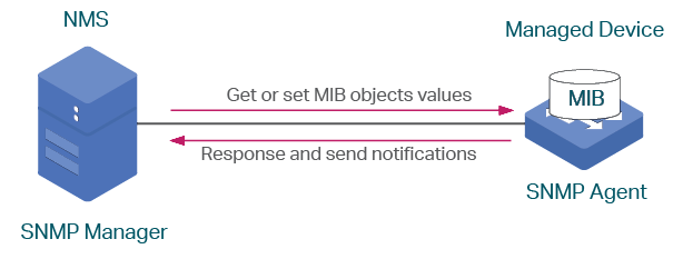
SNMP (Simple Network Management Protocol) is a standard network management protocol, widely used on TCP/IP networks. It facilitates device management using NMS (Network Management System) software. With SNMP, network managers can view or modify network device information, and troubleshoot according to notifications sent by those devices in a timely manner.
As the following figure shows, the SNMP system consists of an SNMP manager, an SNMP agent, and a MIB (Management Information Base). The SNMP manager can be part of an NMS such as tpNMS. The agent and MIB reside on the managed device such as the switch, router, host or printer. To configure SNMP on the switch, you define the relationship between the manager and the agent.
Figure 1-1 SNMP System
1.2Basic Concepts
The following basic concepts of SNMP will be introduced: SNMP manager, SNMP agent, MIB (Management Information Base), SNMP entity, SNMP engine, and SNMP version.
SNMP Manager
The SNMP manager uses SNMP to monitor and control SNMP agents, providing a friendly management interface for the administrator to manage network devices conveniently. It can get an MIB objects values from an agent or store a value of MIB object into the agent. Also, it receives notifications from the agents so as to learn the condition of the network.
SNMP Agent
An SNMP agent is a process running on the managed device. It contains MIB objects whose values can be requested or changed by the SNMP manager. An agent can send unsolicited trap messages to notify the SNMP manager that a significant event has occurred on the agent.
MIB
A MIB is a collection of managed objects that is organized hierarchically. The objects define the attributes of the managed device, including the names, status, access rights, and data types. Each object can be addressed through an object identifier (OID).
As the following figure shows, the MIB hierarchy can be depicted as a tree with a nameless root, the levels of which are assigned by different organizations. The top-level MIB object IDs belong to different standards organizations, while lower-level object IDs are allocated by associated organizations. Vendors can define private branches that include managed objects for their own products.
Figure 1-2 MIB Tree
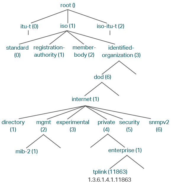
TP-Link switches provide private MIBs that can be identified by the OID 1.3.6.1.4.1.11863. The MIB file can be found on the provided CD or the download center of our official website:
https://www.tp-link.com/en/download-center.html.
Also, TP-Link switches support the following public MIBs:
LLDP.mib
LLDP-Ext-Dot1.mib
LLDP-Ext-MED.mib
RFC1213.mib
RFC1493-Bridge.mib
RFC1757-RMON.mib
RFC2618-RADIUS-Auth-Client.mib
RFC2620-RADIUS-Acc-Client.mib
RFC2674-pBridge.mib
RFC2674-qBridge.mib
RFC2863-pBridge.mib
RFC2925-Disman-Ping.mib
RFC2925-Disman-Traceroute.mib
For detail information about the supported public MIBs, see Supported Public MIBs for TP-Link Switches which can be found on the training center of our website:
https://www.tp-link.com/en/configuration-guides.html
SNMP Entity
An SNMP entity is a device running the SNMP protocol. Both the SNMP manager and SNMP agent are SNMP entities.
SNMP Engine
An SNMP engine is a part of the SNMP entity. Every SNMP entity has one and only one engine. An SNMP engine provides services for ending and receiving messages, authenticating and encrypting messages, and controlling access to managed objects.
An SNMP engine can be uniquely identified by an engine ID within an administrative domain. Since there is a one-to-one association between SNMP engines and SNMP entities, we can also use the engine ID to uniquely and unambiguously identify the SNMP entity within that administrative domain.
SNMP Version
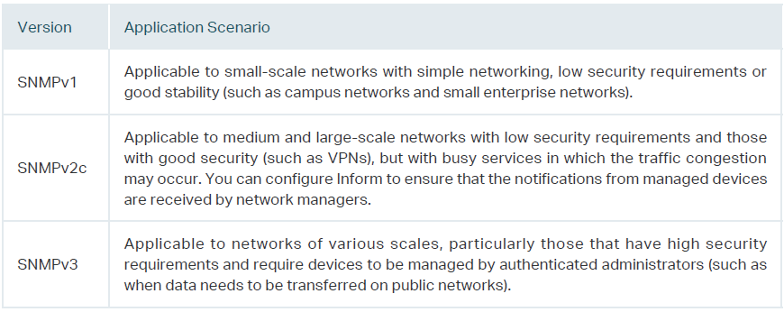
The device supports three SNMP versions: SNMPv1, SNMPv2c and SNMPv3. Table 1-1 lists features supported by different SNMP versions, and Table 1-2 shows corresponding application scenarios.
Table 1-1Features Supported by Different SNMP Versions
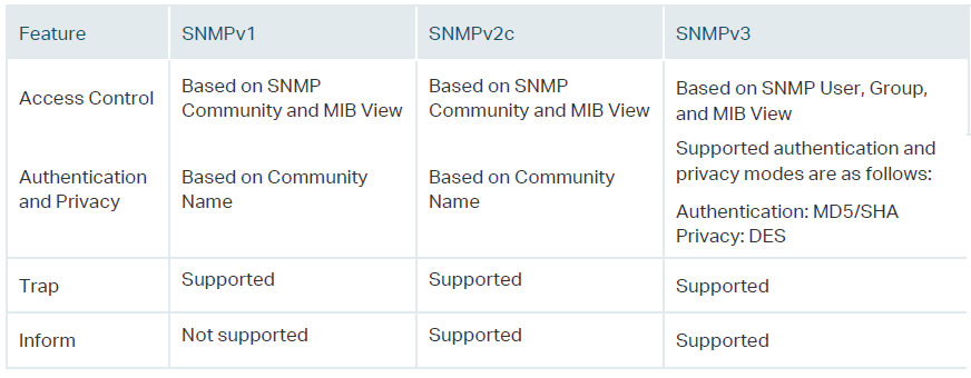
Table 1-2Application Scenarios of Different Versions
To complete the SNMP configuration, choose an SNMP version according to network requirements and supportability of the NMS software, and then follow these steps:
1)Enable SNMP.
2)Create an SNMP view for managed objects.
3)Create a community, specify the accessible view and the corresponding access rights.
Choose SNMPv3
1)Enable SNMP.
2)Create an SNMP view for managed objects.
3)Create an SNMP group, and specify the access rights.
4)Create SNMP users, and configure the authentication mode, privacy mode and corresponding passwords.
2.1Using the GUI
2.1.1Enabling SNMP
Choose the MAINTENANCE > SNMP > Global Config to load the following page.
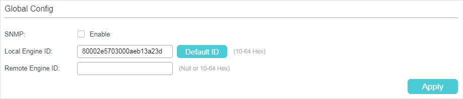
Figure 2-1 Global Config
Follow these steps to configure SNMP globally:
1)In the Global Config section, enable SNMP and configure the local and remote engine ID.
|
SNMP |
Enable or disable SNMP globally. |
|
Local Engine ID |
Set the engine ID of the local SNMP agent (the switch) with 10 to 64 hexadecimal digits. By default, the switch generates the engine ID using TP-Link’s enterprise number (80002e5703) and its own MAC address. The local engine ID is a unique alphanumeric string used to identify the SNMP engine. As an SNMP agent contains only one SNMP engine, the local engine ID can uniquely identify the SNMP agent. |
|
Remote Engine ID |
Set the ID of the remote SNMP manager with 10 to 64 hexadecimal digits. If no remote SNMP manager is needed, you can leave this field empty. The remote engine ID is a unique alphanumeric string. It is used to identify the SNMP engine on the remote device thats receives inform messages from Switch. |
2)Click Apply.
|
|
Note: •The engine ID must contain an even number of characters. •Changing the value of the SNMP engine ID has important side effects. In SNMPv3, a user’s password is converted to an MD5 or SHA security digest based on the password and the engine ID. If the value of local engine ID changes, the switch will automatically delete all SNMPv3 local users as their security digests become invalid. Similarly, all SNMPv3 remote users will be deleted if the value of remote engine ID changes. |

2.1.2Creating an SNMP View
Choose the menu MAINTENANCE > SNMP > Global Config to load the following page.
Figure 2-2 SNMP View Config
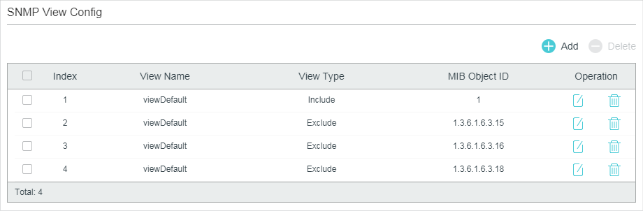
NMS manages MIB objects based on the SNMP view. An SNMP view is a subset of a MIB. The system provides a default view named viewDefault, and you can create other SNMP views according to your needs.
Follow these steps to create an SNMP view:
1)Click  to load the following page. Enter a view name, and specify the view type and a MIB object that is related to the view.
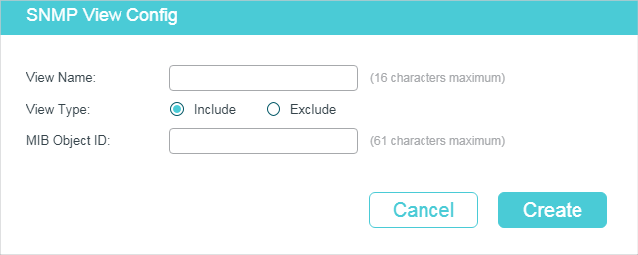
Figure 2-3 Creating an SNMP View
|
View Name |
Set the view name with 1 to 16 characters. A complete view consists of all MIB objects that have the same view name. |
|
View Type |
Set the view to include or exclude the related MIB object. By default, it is include. Include: The NMS can view or manage the function indicated by the object. Exclude: The NMS cannot view or manage the function indicated by the object. |
|
MIB Object ID |
Enter a MIB Object ID to specify a specific function of the device. When a MIB Object ID is specified, all its child Object IDs are specified. For specific ID rules, refer to the device related MIBs. |
2)Click Create.
2.1.3Creating SNMP Communities (For SNMP v1/v2c)
Choose the menu MAINTENANCE > SNMP > SNMP v1/v2c and click to load the following page.
Figure 2-4 Creating an SNMP Community
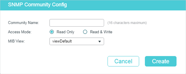
1)Set the community name, access rights and the related view.
|
Community Name |
Configure the community name. This community name is used like a password to give the NMS access to MIB objects in the switch’s SNMP agent. |
|
Access Mode |
Specify the access right to the related view. The default is read-only. Read Only: The NMS can view but not modify parameters of the specified view. Read & Write: The NMS can view and modify parameters of the specified view. |
|
MIB View |
Choose an SNMP view that allows the community to access. The default view is viewDefault. |
2)Click Create.
2.1.4Creating an SNMP Group (For SNMP v3)
Create an SNMP group and configure related parameters.
Choose the menu MAINTENANCE > SNMP > SNMP v3 > SNMP Group and click  to load the following page.
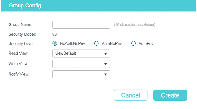
Figure 2-5 Creating an SNMP Group
Follow these steps to create an SNMP Group:
1)Assign a name to the group, then set the security level and the read view, write view and notify view.
|
Group Name |
Set the SNMP group name. You may enter 1 to 16 characters. The identifier of a group consists of a group name, security model and security level. Groups of the same identifier are recognized as being in the same group. |
|
Security Model |
Displays the security model. SNMPv3 uses v3, the most secure model. |
|
Security Level |
Set the security level which for the SNMPv3 group. The default is NoAuthNoPriv. NoAuthNoPriv: No authentication mode or privacy mode is applied to check or encrypt packets. AuthNoPriv: An authentication mode is applied to check packets, but no privacy mode is applied to encrypt them. AuthPriv: An authentication mode and a privacy mode are applied to check and encrypt packets. |
|
Read View |
Choose a view to allow parameters to be viewed but not modified by the NMS. The view is necessary for any group. By default, the view is viewDefault. To modify parameters of a view, you need to add it to Write View. |
|
Write View |
Choose a view to allow parameters to be modified but not viewed by the NMS. The default is none. The view in Write View should also be added to Read View. |
|
Notify View |
Choose a view to allow it to send notifications to the NMS. |
2)Click Create.
2.1.5Creating SNMP Users (For SNMP v3)
Choose the menu MAINTENANCE > SNMP > SNMP v3 > SNMP User and click  to load the following page.
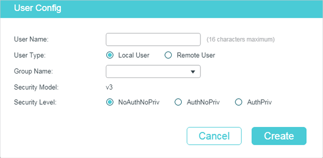
Figure 2-6 Creating an SNMP User
Follow these steps to create an SNMP user:
1)Specify the user name, user type and the group which the user belongs to. Then configure the security level.
|
User Name |
Set the SNMP user name. You may use 1 to 16 characters. For different entries, user names cannot be the same. |
|
User Type |
Choose a user type to indicate the location of the user. The default is Local User. Local User: The user resides on the local engine, which is the SNMP agent of the switch. Remote User: The user resides on the NMS. As the remote engine ID and user password are used to compute the authentication and privacy digests, before configuring a remote user, you need to set the remote engine ID first. |
|
Group Name |
Choose the group that the user belongs to. Users with the same Group Name, Security Model and Security Level will be in the same group. |
|
Security Model |
Displays the security model. SNMPv3 uses v3, the most secure model. |
|
Security Level |
Set the security level. The security level from highest to lowest is: NoAuthNoPriv, AuthNoPriv, AuthPriv, and the default is NoAuthNoPriv. The security level of the user should not be lower than the group it belongs to. NoAuthNoPriv: Uses a username match for authentication, and no encryption is implemented. AuthNoPriv: An authentication mode is applied to check packets, but no privacy mode is applied to encrypt them. AuthPriv: An authentication mode and a privacy mode are applied to check and encrypt packets. |
2)If you have chosen AuthNoPriv or AuthPriv as the security level, you need to set corresponding Authentication Mode or Privacy Mode. If not, skip the step.
|
Authentication Mode |
With AuthNoPriv or AuthPriv selected, configure the authentication mode and password. Two authentication modes are provided: MD5: Enable the HMAC-MD5 algorithm for authentication. SHA: Enable the SHA (Secure Hash Algorithm) algorithm for authentication. SHA algorithm is securer than MD5 algorithm. |
|
Authentication Password |
Set the password for authentication. |
|
Privacy Mode |
With AuthPriv selected, configure the privacy mode and password for encryption. The switch uses the DES (Data Encryption Standard) algorithm for encryption. |
|
Privacy Password |
Set the password for encryption. |
3)Click Create.
2.2Using the CLI
2.2.1Enabling SNMP
|
Step 1 |
configure Enter global configuration mode. |
|
Step 2 |
snmp-server Enabling SNMP. |
|
Step 3 |
snmp-server engineID {[ local local-engineID] [remote remote-engineID]} Configure the local engine ID and the remote engine ID. local-engineID: Enter the engine ID of the local SNMP agent (the switch) with 10 to 64 hexadecimal digits. By default, the switch generates the engine ID using TP-Link’s enterprise number (80002e5703) and its own MAC address. The local engine ID is a unique alphanumeric string used to identify the SNMP engine. As an SNMP agent contains only one SNMP engine, the local engine ID can uniquely identify the SNMP agent. remote-engineID: Enter the remote engine ID with 10 to 64 hexadecimal digits. The ID must contain an even number of characters. The remote engine ID is a unique alphanumeric string. It is used to identify the SNMP engine on the remote device that receives inform messages from switch. Note: Changing the value of the SNMP engine ID has important side effects. In SNMPv3, a user’s password is converted to an MD5 or SHA security digest based on the password and the engine ID. If the value of local engine ID changes, the switch will automatically delete all SNMPv3 local users as their security digests become invalid. Similarly, all SNMPv3 remote users will be deleted if the value of remote engine ID changes. |
|
Step 4 |
show snmp-server Displays the global settings of SNMP. |
|
Step 5 |
show smnp-server engineID Displays the engine ID of SNMP. |
|
Step 6 |
end Return to privileged EXEC mode. |
|
Step 7 |
copy running-config startup-config Save the settings in the configuration file. |
The following example shows how to enable SNMP and set 123456789a as the remote engine ID:
Switch#configure
Switch(config)#snmp-server
Switch(config)#snmp-server engineID remote 123456789a
Switch(config)#show snmp-server
SNMP agent is enabled.
0 SNMP packets input
0 Bad SNMP version errors
0 Unknown community name
0 Illegal operation for community name supplied
0 Encoding errors
0 Number of requested variables
0 Number of altered variables
0 Get-request PDUs
0 Get-next PDUs
0 Set-request PDUs
0 SNMP packets output
0 Too big errors (Maximum packet size 1500)
0 No such name errors
0 Bad value errors
0 General errors
0 Response PDUs
0 Trap PDUs
Switch(config)#show snmp-server engineID
Local engine ID: 80002e5703000aeb13a23d
Remote engine ID: 123456789a
Switch(config)#end
Switch#copy running-config startup-config
2.2.2Creating an SNMP View
Specify the OID (Object Identifier) of the view to determine objects to be managed.
|
Step 1 |
configure Enter global configuration mode. |
|
Step 2 |
snmp-server view name mib-oid {include | exclude} Configure the view. name: Enter a view name with 1 to 16 characters. You can create multiple entries with each associated to a MIB object. A complete view consists of all MIB objects that have the same view name. mib-oid: Enter the MIB object ID with 1 to 61 characters. include | exclude: Specify a view type. Include indicates that objects of the view can be managed by the NMS, while exclude indicates that objects of the view cannot be managed by the NMS. |
|
Step 3 |
show snmp-server view Displays the view table. |
|
Step 4 |
end Return to Privileged EXEC Mode. |
|
Step 5 |
copy running-config startup-config Save the settings in the configuration file. |
The following example shows how to set a view to allow the NMS to manage all function. Name the view as View:
Switch#configure
Switch(config)#snmp-server view View 1 include
Switch(config)#show snmp-server view
No. View Name Type MOID
--- ------------ ------- ----
1 viewDefault include 1
2 viewDefault exclude 1.3.6.1.6.3.15
3 viewDefault exclude 1.3.6.1.6.3.16
4 viewDefault exclude 1.3.6.1.6.3.18
5 View include 1
Switch(config)#end
Switch#copy running-config startup-config
2.2.3Creating SNMP Communities (For SNMP v1/v2c)
For SNMPv1 and SNMPv2c the Community Name is used for authentication, functioning as the password.
|
Step 1 |
configure Enter global configuration mode. |
|
Step 2 |
snmp-server community name { read-only | read-write } [mib-view] Configure the community. name: Enter a group name with 1 to 16 characters. read-only | read-write: Choose an access permissions for the community. Read-only indicates that the NMS can view but cannot modify parameters of the view, while read-write indicates that the NMS can both view and modify. mib-view: Enter a view to allow it to be accessed by the community. The name contains 1 to 61 characters. The default view is viewDefault. |
|
Step 3 |
show snmp-server community Displays community entries. |
|
Step 4 |
end Return to privileged EXEC mode. |
|
Step 5 |
copy running-config startup-config Save the settings in the configuration file. |
The following example shows how to set an SNMP community. Name the community as the nms-monitor, and allow the NMS to view and modify parameters of View:
Switch#configure
Switch(config)#snmp-server community nms-monitor read-write View
Switch(config)#show snmp-server community
Index Name Type MIB-View
----- ---------------- ------------ --------
1 nms-monitor read-write View
Switch(config)#end
Switch#copy running-config startup-config
2.2.4Creating an SNMP Group (For SNMPv3)
Create an SNMP group and set user access control with read, write and notify views. Meanwhile, set the authentication and privacy modes to secure the communication between the NMS and managed devices.
|
Step 1 |
configure Enter global configuration mode. |
|
Step 2 |
snmp-server group name [ smode v3 ] [ slev {noAuthNoPriv | authNoPriv | authPriv}] [ read read-view ] [ write write-view ] [ notify notify-view ] Create an SNMP group. name: Enter the group name with 1 to 16 characters. The identifier of a group consists of a group name, security model and security level. Groups of the same identifier are recognized as being in the same group. v3: Configure the security mode for the group. v3 indicates SNMPv3, the most secure model. noAuthNoPriv | authNoPriv | authPriv: Choose a security level among noAuthNoPriv (no authorization and no encryption), authNoPriv (authorization and no encryption), authPriv (authorization and encryption). The default is noAuthNoPriv. Please note that if you have chosen v1 or v2c as the security mode, the security level cannot be configured. read-view: Set the view to be the Read view. Then the NMS can view parameters of the specified view. write-view: Set the view to be the Write view. Then the NMS can modify parameters of the specified view. Please note that the view in the Write view should also be in the Read view. notify-view: Set the view to be the Notify view. Then the NMS can get notifications of the specified view from the agent. |
|
Step 3 |
show snmp-server group Displays SNMP group entries. |
|
Step 4 |
end Return to Privileged EXEC Mode. |
|
Step 5 |
copy running-config startup-config Save the settings in the configuration file. |
The following example shows how to create an SNMPv3 group with the group name as nms1, the security level as authPriv, and the Read and Notify view are both View1:
Switch#configure
Switch(config)#snmp-server group nms1 smode v3 slev authPriv read View1 notify View1
Switch(config)#show snmp-server group
No. Name Sec-Mode Sec-Lev Read-View Write-View Notify-View
--- -------- ------------- ---------- ------------- ------------- --------------
1 nms1 v3 authPriv View1 View1
Switch(config)#end
Switch#copy running-config startup-config
2.2.5Creating SNMP Users (For SNMPv3)
Configure users of the SNMP group. Users belong to the group, and use the same security level and access rights as the group.
|
Step 1 |
configure Enter global configuration mode. |
|
Step 2 |
snmp-server user name { local | remote } group-name [ smode v3 ] [ slev { noAuthNoPriv | authNoPriv | authPriv }] [ cmode { none | MD5 | SHA }] [ cpwd confirm-pwd ] [ emode { none | DES }] [ epwd encrypt-pwd ] Configure users of the SNMP group. name: Enter the user name with 1 to 16 characters. local | remote: Choose a user type. Local indicates that the user is connected to a local SNMP engine, while remote means that the user is connected to a remote SNMP engine. As the remote engine ID and user password are used to compute the authentication and privacy digests, before configuring a remote user, you need to set the remote engine ID first. group-name: Enter the name of the group which the user belongs to. The group is determined by the group name, security mode and security level. v3: Configure the security mode for the user. v3 indicates SNMPv3, the most secure model. noAuthNoPriv | authNoPriv | authPriv: Choose a security level from noAuthNoPriv (no authorization and no encryption), authNoPriv (authorization and no encryption), authPriv (authorization and encryption). The security level from highest to lowest is: noAuthNoPriv, authNoPriv, authPriv, and the default is noAuthNoPriv. The security level of the user should not be lower than the group it belongs to. none | MD5 | SHA: Choose an authentication algorithm. SHA authentication mode has a higher security than MD5 mode. By default, the Authentication Mode is none. confirm-pwd: Enter an authentication password with 1 to 16 characters excluding question mark and space. This password in the configuration file will be displayed in the symmetric encrypted form. none | DES: Choose a privacy mode. None indicates no privacy method is used, and DES indicates DES encryption method is used. By default, the Privacy Mode is none. encrypt-pwd: Enter a privacy password with 1 to 16 characters excluding question mark and space. This password in the configuration file will be displayed in the symmetric encrypted form. |
|
Step 3 |
show snmp-server user Displays the information of SNMP users. |
|
Step 4 |
end Return to privileged EXEC mode. |
|
Step 5 |
copy running-config startup-config Save the settings in the configuration file. |
The following example shows how to create an SNMP user and add it to group nms1. Name the user as admin, and set the user as a remote user, SNMPv3 as the security mode, authPriv as the security level, SHA as the authentication algorithm, 1234 as the authentication password, DES as the privacy algorithm and 1234 as the privacy password:
Switch#configure
Switch(config)#snmp-server user admin remote nms1 smode v3 slev authPriv cmode SHA cpwd 1234 emode DES epwd 1234
Switch(config)#show snmp-server user
No. U-Name U-Type G-Name S-Mode S-Lev A-Mode P-Mode
--- ------ ------ ------ ------ ----- ------ ------
1 admin remote nms1 v3 authPriv SHA DES
Switch(config)#end
Switch#copy running-config startup-config
With Notification enabled, the switch can send notifications to the NMS about important events relating to the device’s operation. This facilitates the monitoring and management of the NMS.
To configure SNMP notification, follow these steps:
1)Configure the information of NMS hosts.
2)Enable SNMP traps.
Configuration Guidelines
To guarantee the communication between the switch and the NMS, ensure the switch and the NMS are able to reach one another.
3.1Using the GUI
3.1.1Configuring the Information of NMS Hosts
Choose the menu MAINTENANCE > SNMP > Notification > Notification Config and click to load the following page.
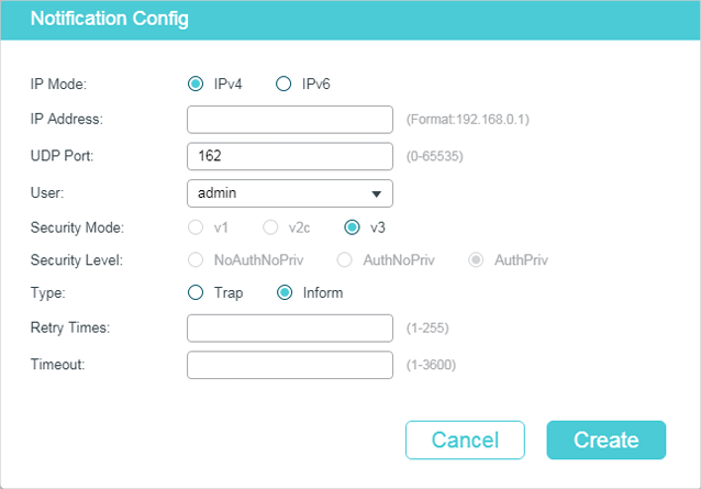
Figure 3-1 Adding an NMS Host
Follow these steps to add an NMS host:
1)Choose the IP mode according to the network environment, and specify the IP address of the NMS host and the UDP port that receives notifications.
|
IP Mode |
Choose an IP mode for the NMS host. |
|
IP Address |
If you set the IP Mode as IPv4, specify an IPv4 address for the NMS host. If you set the IP Mode as IPv6, specify an IPv6 address for the NMS host. |
|
UDP Port |
Specify a UDP port on the NMS host to receive notifications. The default is port 162. For communication security, we recommend that you change the port number under the condition that communications on other UDP ports are not affected. |
Specify the user name or community name used by the NMS host, and configure the security model and security level based on the settings of the user or community.
|
User Name |
Choose the user name or community name used by the NMS host. |
|
Security Mode |
If a community name (created for SNMPv1/v2c) is entered in User Name, specify the security mode as v1 or v2c. If a user name (created for SNMPv3) is entered in User Name, here displays the security mode as v3. The NMS host should use the corresponding SNMP version. |
|
Security Level |
If Security Level is v3, displays the security level of the user. |
2)Choose a notification type based on the SNMP version. If you choose the Inform type, you need to set retry times and timeout interval.
|
Type |
Choose a notification type for the NMS host. For SNMPv1, the supported type is trap. For SNMPv2c and SNMPv3, you can configure the type as trap or inform. Trap: The switch will send Trap messages to the NMS host when certain events occur. When the NMS host receives a Trap message, it will not send a response to the switch. Thus the switch cannot tell whether a message is received or not, and the messages that are not received will not be resent. Inform: The switch will send Inform messages to the NMS host when certain events occur. When the NMS host receives an Inform message, it sends a response to the switch. If the switch does not receive a response within the timeout interval, it will resend the Inform message. Therefore, Informs are more reliable than Traps. |
|
Retry |
Set the retry times for Informs. The switch will resend the Inform message if it does not receive response from the NMS host within the timeout interval. It will stop sending Inform messages when the retry time reaches the limit. |
|
Timeout |
Set the length of time that the switch waits for a response from the NMS host after sending an inform message. |
3)Click Create.
3.1.2Enabling SNMP Traps
Choose the menu MAINTENANCE > SNMP > Notification > Trap Config to load the following page.
Figure 3-2 Enabling SNMP Traps
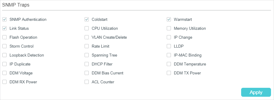
The supported traps are listed on the page. Follow these steps to enable any or all of these traps:
1)Select the traps to enable according to your needs.
|
SNMP Authentication |
Triggered when a received SNMP request fails the authentication. |
|
Coldstart |
Indicates an SNMP initialization caused by the reinitialization of the switch system. The trap can be triggered when you reboot the switch. |
|
Warmstart |
Indicates the SNMP feature on the switch is reinitialized with the physical configuration unchanged. The trap can be triggered if you disable and then enable SNMP after the SNMP is completely configured and enabled. |
|
Link Status |
Triggered when the switch detects a link status change. |
|
CPU Utilization |
Triggered when the utilization rate of the CPU has exceeded the limit that you have set. The limit of CPU utilization rate for the switch is 80% by default. |
|
Memory Utilization |
Triggered when the memory utilization exceeds 80%. |
|
Flash Operation |
Triggered when flash is modified during operations such as backup, reset, firmware upgrade, configuration import, and so on. |
|
VLAN Create/Delete |
Triggered when certain VLANs are created or deleted successfully. |
|
IP Change |
Monitors the IP address changes of each interface. The trap can be triggered when the IP address of any interface is changed. |
|
Storm Control |
Monitors whether the storm rate has reached the limit that you have set. The trap can be triggered when the feature is enabled and broadcast/multicast/unknown-unicast frames are sent to the port with a rate higher than what you have set. |
|
Rate Limit |
Monitors whether the bandwidth has reached the limit you have set. The trap can be triggered when the Rate Limit feature is enabled and packets are sent to the port with a rate higher than what you have set. |
|
LLDP |
Indicates LLDP topology changes. The trap can be triggered when a new remote device attached to a local port, or a remote device disconnected or moved from one port to another. |
|
Loopback Detection |
Triggered when the switch detects a loopback with loopback detection feature, or when a loopback is cleared. |
|
Spanning Tree |
Indicates spanning tree changes. The trap can be triggered in the following situations: a port changes from non-forwarding state to forwarding state or the other way round; a port receives a packet with TC flag or a TCN packet. |
|
PoE |
Only for products that support PoE feature. Allow all PoE-related traps, including: Over-max-pwr-budget: Triggered when the total power required by the connected PDs exceeds the maximum power the PoE switch can supply. Port-pwr-change: Triggered when a port starts to supply power or stops supplying power. Port-pwr-deny: Triggered when the switch powers off PDs on low-priority PoE ports. When the total power required by the connected PDs exceeds the system power limit, the switch will power off PDs on low-priority PoE ports to ensure stable running of the other PDs. Port-pwr-over-30w: Triggered when the power required by the connected PD exceeds 30 watts. Port-pwr-overload: Triggered when the power required by the connected PD exceeds the maximum power the port can supply. Port-short-circuit: Triggered when a short circuit is detected on a port. Thermal-shutdown: Triggered when the PSE chip overheats. The switch will stop supplying power in this case. |
|
IP-MAC Binding |
Triggered in the following two situations: the ARP Inspection feature is enabled and the switch receives an illegal ARP packet; or the IPv4 Source Guard feature is enabled and the switch receives an illegal IP packet. |
|
IP Duplicate |
Triggered when the switch detects an IP conflict event. |
|
DHCP Filter |
Triggered when the DHCPv4 Filter feature is enabled and the switch receives DHCP packets from an illegal DHCP server. |
|
DDM Temperature |
Only T2600G-28TS supports DDM traps. Monitors the temperature of SFP modules inserted into the SFP ports on the switch. The trap can be triggered when the temperature of any SFP module has reached the warning or alarm threshold. |
|
DDM Voltage |
Only T2600G-28TS supports DDM traps. Monitors the voltage of SFP modules inserted into the SFP ports on the switch. The trap can be triggered when the voltage of any SFP module has reached the warning or alarm threshold. |
|
DDM Bias Current |
Only T2600G-28TS supports DDM traps. Monitors the bias current of SFP modules inserted into the SFP ports on the switch. The trap can be triggered when the bias current of any SFP module has reached the warning or alarm threshold. |
|
DDM TX Power |
Only T2600G-28TS supports DDM traps. Monitors the TX Power of SFP modules inserted into the SFP ports on the switch. The trap can be triggered when the TX Power of any SFP module has reached the warning or alarm threshold. |
|
DDM RX Power |
Only T2600G-28TS supports DDM traps. Monitors the RX Power of SFP modules inserted into the SFP ports on the switch. The trap can be triggered when the RX Power of any SFP module has reached the warning or alarm threshold. |
|
ACL Counter |
Monitors matched ACL information, including the matched ACL ID, rule ID and the number of the matched packets. With both this trap and the Logging feature in ACL rule settings enabled, the switch will check the matched ACL information every five minutes and send SNMP traps if there is any updated information. |
2)Click Apply.
3.2Using the CLI
3.2.1Configuring the NMS Host
Configure parameters of the NMS host and packet handling mechanism.
|
Step 1 |
configure Enter global configuration mode. |
|
Step 2 |
snmp-server host ip udp-port user-name [smode { v1 | v2c | v3 }] [slev {noAuthNoPriv | authNoPriv | authPriv }] [type { trap | inform}] [retries retries] [timeout timeout] Configure parameters of the NMS host and packet handling mechanism. ip: Specify the IP address of the NMS host in IPv4 or IPv6. Please make sure the IP addresses of the NMS host and the switch are able to reach to each other. udp-port: Specify a UDP port on the NMS host to receive notifications. The default is port 162. For communication security, we recommend that you change the port number under the condition that communications on other UDP ports are not affected. user-name: Enter the name used by the NMS host. When the NMS host uses SNMPv1 or SNMPv2c, enter the Community Name; when the NMS host uses SNMPv3, enter the User Name of the SNMP Group. v1 | v2c | v3: Choose the security mode used by the user from the following: SNMPv1, SNMPv2c, SNMPv3. The NMS host should use the corresponding SNMP version. noAuthNoPriv | authNoPriv | authPriv: For SNMPv3 groups, choose a security level from noAuthNoPriv (no authorization and no encryption), authNoPriv (authorization and no encryption), authPriv (authorization and encryption). The defaut is noAuthNoPriv. Please note that if you have chosen v1 or v2c as the security mode, security level cannot be configured. trap | inform: Choose a notification type for the NMS host. For SNMPv1, the supported type is trap. For SNMPv2c and SNMPv3, you can configure the type as trap or inform. When the NMS host receives a trap message, it will not send a response to the switch. Thus the switch cannot tell whether a message is received or not, and the messages that are not received will not be resent. When the NMS host receives an Inform message, it sends a response to the switch. If the switch does not receive a response within the Timeout interval, it will resend the Inform message. Therefore, Informs are more reliable than Traps. retries: Set the retry times for Inform messages. The range is 1 to 255 and the default is 3. The switch will resend the Inform message if it does not receive response from the NMS host within the timeout interval. And it will stop sending Inform message when the retry times reaches the limit. timeout: Set the length of time that the switch waits for a response. The range is 1 to 3600 seconds; the default is 100 seconds. The switch will resend the Inform message if it does not receive a response from the NMS host within the timeout interval. |
|
Step 3 |
show snmp-server host Displays the information of the host. |
|
Step 4 |
end Return to privileged EXEC mode. |
|
Step 5 |
copy running-config startup-config Save the settings in the configuration file. |
The following example shows how to set the NMS host IP address as 192.30.1.222, UDP port as port 162, name used by the NMS host as admin, security model as SNMPv3, security level as authPriv, notification type as Inform, retry times as 3, and the timeout interval as 100 seconds:
Switch#configure
Switch(config)#snmp-server host 192.30.1.222 162 admin smode v3 slev authPriv type inform retries 3 timeout 100
Switch(config)#show snmp-server host
No. Des-IP UDP Name SecMode SecLev Type Retry Timeout
--- ------ ----- ---- ------- ------ ---- ----- -------
1 192.30.1.222 162 admin v3 authPriv inform 3 100
Switch(config)#end
Switch#copy running-config startup-config
3.2.2Enabling SNMP Traps
The switch supports multiple SNMP traps like SNMP standard traps, ACL traps, and VLAN traps. You can enable any or all of the traps according to your needs.
Enabling the SNMP Standard Traps Globally
|
Step 1 |
configure Enter global configuration mode. |
|
Step 2 |
snmp-server traps snmp [ linkup | linkdown | warmstart | coldstart | auth-failure ] Enable the corresponding SNMP standard traps. The command without parameter enables all SNMP standard traps. All SNMP standard traps are enabled by default. linkup: Indicates a port status changes from linkdown to linkup, and can be triggered when you connect a device to a port. linkdown: Indicates a port status changes from linkup to linkdown, and can be triggered when you disconnect a device to a port. warmstart: Indicates the SNMP feature on the switch is reinitialized with the physical configuration unchanged. The trap can be triggered if you disable and then enable SNMP after the SNMP is completely configured and enabled. coldstart: Indicates an SNMP initialization caused by the reinitialization of the switch system. The trap can be triggered when you reboot the switch. auth-failure: Triggered when a received SNMP request fails the authentication. |
|
Step 3 |
end Return to privileged EXEC mode. |
|
Step 4 |
copy running-config startup-config Save the settings in the configuration file. |
The following example shows how to configure the switch to send linkup traps:
Switch#configure
Switch(config)#snmp-server traps snmp linkup
Switch(config)#end
Switch#copy running-config startup-config
Enabling the SNMP Extended Traps Globally
|
Step 1 |
configure Enter global configuration mode. |
|
Step 2 |
snmp-server traps { rate-limit | cpu | flash | lldp remtableschange | lldp topologychange | loopback-detection | storm-control | spanning-tree | memory } Enable the corresponding SNMP extended traps. All SNMP extended traps are disabled by default. rate-limit: Monitors whether the bandwidth has reached the limit you have set. The trap can be triggered when the Rate Limit feature is enabled and packets are sent to the port with a rate higher than what you have set. cpu: Monitors the load status of the switch CPU. The trap can be triggered when the utilization rate of the CPU has exceeded the limit that you have set. The limit of CPU utilization rate for the switch is 80% by default. flash: Triggered when flash is modified during operations such as backup, reset, firmware upgrade, configuration import, and so on. lldp remtableschange: A lldp RemTablesChange notification is sent when the value of lldp StatsRemTableLastChangeTime changes. It can be utilized by an NMS host to trigger LLDP remote systems table maintenance polls. lldp topologychange: A notification generated by the local device to sense the change in the topology that indicates a new remote device attached to a local port, or a remote device disconnected or moved from one port to another. loopback-detection: The feature is used to detect loopbacks. And the trap is disabled by default. The system will generate the trap when a loopback is detected or cleared. storm-control: The feature is used to monitor network storms. And the trap is disabled by default. The system will generate the trap when the rate of broadcast or multicast reaches the limit of storm control. spanning-tree: The feature is used to monitor the spanning tree status. And the trap is disabled by default. The system will generate the trap in the following situations: a port changes from non-forwarding state to forwarding state or the other way round; a port receives a packet with TC flag or a TCN packet. memory: The feature is used to monitor the memory. And the trap is disabled by default. The system will generate the trap when the memory utilization exceeds 80%. |
|
Step 3 |
end Return to privileged EXEC mode. |
|
Step 4 |
copy running-config startup-config Save the settings in the configuration file. |
The following example shows how to configure the switch to enable bandwidth-control traps:
Switch#configure
Switch(config)#snmp-server traps bandwidth-control
Switch(config)#end
Switch#copy running-config startup-config
Enabling the DDM Traps Globally
|
|
Note: Only T2600G-28TS supports DDM traps. |
|
Step 1 |
configure Enter global configuration mode. |
|
Step 2 |
snmp-server traps ddm [ temperature | voltage | bias_current | tx_power | rx_power ] Enable the corresponding DDM traps. DDM function is used to monitor the status of the SFP modules inserted into the SFP ports on the switch. The command without parameter enables all SNMP DDM traps. All DDM traps are disabled by default. temperature: Monitors the temperature of SFP modules inserted into the SFP ports on the switch. The trap can be triggered when the temperature of any SFP module has reached the warning or alarm threshold. voltage: Monitors the voltage of SFP modules inserted into the SFP ports on the switch. The trap can be triggered when the voltage of any SFP module has reached the warning or alarm threshold. bias_current: Monitors the bias current of SFP modules inserted into the SFP ports on the switch. The trap can be triggered when the bias current of any SFP module has reached the warning or alarm threshold. tx_power: Monitors the TX Power of SFP modules inserted into the SFP ports on the switch. The trap can be triggered when the TX Power of any SFP module has reached the warning or alarm threshold. rx_power: Monitors the RX Power of SFP modules inserted into the SFP ports on the switch. The trap can be triggered when the RX Power of any SFP module has reached the warning or alarm threshold. |
|
Step 3 |
end Return to privileged EXEC mode. |
|
Step 4 |
copy running-config startup-config Save the settings in the configuration file. |
The following example shows how to configure the switch to enable DDM temperature trap:
Switch#configure
Switch(config)#snmp-server traps DDM temperature
Switch(config)#end
Switch#copy running-config startup-config
Enabling the VLAN Traps Globally
|
Step 1 |
configure Enter global configuration mode. |
|
Step 2 |
snmp-server traps vlan [ create | delete ] Enable the corresponding VLAN traps. The command without parameter enables all SNMP VLAN traps. All VLAN traps are disabled by default. create: Triggered when certain VLANs are created successfully. delete: Triggered when certain VLANs are deleted successfully. |
|
Step 3 |
end Return to privileged EXEC mode. |
|
Step 4 |
copy running-config startup-config Save the settings in the configuration file. |
The following example shows how to configure the switch to enable all the SNMP VLAN traps:
Switch#configure
Switch(config)#snmp-server traps vlan
Switch(config)#end
Switch#copy running-config startup-config
Enabling the SNMP Security Traps Globally
|
Step 1 |
configure Enter global configuration mode. |
|
Step 2 |
snmp-server traps security { dhcp-filter | ip-mac-binding } Enable the corresponding security traps. All security traps are disabled by default. dhcp-filter: Triggered when the DHCPv4 Filter feature is enabled and the switch receives DHCP packets from an illegal DHCP server. ip-mac-binding: Triggered when the ARP Inspection feature is enabled and the switch receives an illegal ARP packet, or the IPv4 Source Guard feature is enabled and the switch receives an illegal IP packet. |
|
Step 3 |
end Return to privileged EXEC mode. |
|
Step 4 |
copy running-config startup-config Save the settings in the configuration file. |
The following example shows how to configure the switch to enable DHCP filter trap:
Switch#configure
Switch(config)#snmp-server traps security dhcp-filter
Switch(config)#end
Switch#copy running-config startup-config
Enabling the ACL Trap Globally
|
Step 1 |
configure Enter global configuration mode. |
|
Step 2 |
snmp-server traps security acl Enable the ACL trap. It is disabled by default. The trap monitors matched ACL information, including the matched ACL ID, rule ID and the number of the matched packets. With both this trap and the Logging feature in ACL rule settings enabled, the switch will check the matched ACL information every five minutes and send SNMP traps if there is any updated information. |
|
Step 3 |
end Return to privileged EXEC mode. |
|
Step 4 |
copy running-config startup-config Save the settings in the configuration file. |
The following example shows how to configure the switch to enable ACL trap:
Switch#configure
Switch(config)#snmp-server traps acl
Switch(config)#end
Switch#copy running-config startup-config
Enabling the IP Traps Globally
|
Step 1 |
configure Enter global configuration mode. |
|
Step 2 |
snmp-server traps ip { change | duplicate } Enable the IP traps. All IP traps are disabled by default. change: Enable SNMP IP change traps. The trap monitors the IP changed of each interface. The trap can be triggered when the IP address of any interface is changed. duplicate: Enable SNMP IP duplicate traps. The trap can be triggered when the switch detects an IP conflict event. |
|
Step 3 |
end Return to privileged EXEC mode. |
|
Step 4 |
copy running-config startup-config Save the settings in the configuration file. |
The following example shows how to configure the switch to enable IP-Change trap:
Switch#configure
Switch(config)#snmp-server traps ip change
Switch(config)#end
Switch#copy running-config startup-config
Enabling the SNMP PoE Traps Globally
|
|
Note: Only T2600G-28MPS supports PoE traps. |
|
Step 1 |
configure Enter global configuration mode. |
|
Step 2 |
snmp-server traps power [over-max-pwr-budget | port-pwr-change | port-pwr-deny | port-pwr-over-30w | port-pwr-overload | port-short-circuit | thermal-shutdown ] Enable the PoE traps. The command without parameter enables all PoE traps. All PoE traps are disabled by default. over-max-pwr-budget: Triggered when the total power required by the connected PDs exceeds the maximum power the PoE switch can supply. port-pwr-change: Triggered when the total power required by the connected PDs exceeds the maximum power the PoE switch can supply. port-pwr-deny: Triggered when the switch powers off PDs on low-priority PoE ports. When the total power required by the connected PDs exceeds the system power limit, the switch will power off PDs on low-priority PoE ports to ensure stable running of the other PDs. port-pwr-over-30w: Triggered when the power required by the connected PD exceeds 30 watts. port-pwr-overload: Triggered when the power required by the connected PD exceeds the maximum power the port can supply. port-short-circuit: Triggered when a short circuit is detected on a port. thermal-shutdown: Triggered when the PSE chip overheats. The switch will stop supplying power in this case. |
|
Step 3 |
end Return to privileged EXEC mode. |
|
Step 4 |
copy running-config startup-config Save the settings in the configuration file. |
The following example shows how to configure the switch to enable all PoE traps:
Switch#configure
Switch(config)#snmp-server traps power
Switch(config)#end
Switch#copy running-config startup-config
Enabling the Link-status Trap for Ports
|
Step 1 |
configure Enter global configuration mode. |
|
Step 2 |
interface {fastEthernet port | range fastEthernet port-list | gigabitEthernet port | range gigabitEthernet port-list | ten-gigabitEthernet port | range ten-gigabitEthernet port-list ] Configure notification traps on the specified ports. port/port-list: The number or the list of the Ethernet ports that you desire to configure notification traps. |
|
Step 3 |
snmp-server traps link-status Enable the link-status trap. It is triggered when the switch detects a link status change. By default, it is disabled. |
|
Step 4 |
end Return to privileged EXEC mode. |
|
Step 5 |
copy running-config startup-config Save the settings in the configuration file. |
The following example shows how to configure the switch to enable link-status trap:
Switch#configure
Switch(config)#interface gigabitEthernet 1/0/1
Switch(config-if)#snmp-server traps link-status
Switch(config-if)#end
Switch#copy running-config startup-config
RMON (Remote Network Monitoring) together with the SNMP system allows the network manager to monitor remote network devices efficiently. RMON reduces traffic flow between the NMS and managed devices, which is convenient for management in large networks.
RMON includes two parts: the NMS and the Agents running on every network device. The NMS is usually a host that runs the management software to manage Agents of network devices. And the Agent is usually a switch or router that collects traffic statistics (such as total packets on a network segment during a certain time period, or total correct packets that are sent to a host). Based on SNMP protocol, the NMS collects network data through communication with Agents. However, the NMS cannot obtain every datum of RMON MIB because of the limited device resources. Generally, the NMS can only get information of the following four groups: Statistics, History, Event and Alarm.
Statistics: Collects Ethernet statistics (like the total received bytes, the total broadcast packets, and the total packets of the specified size) on an interface.
History: Collects a history group of statistics on Ethernet ports for a specified polling interval.
Event: Specifies the action to take when an event is triggered by an alarm. The action can be to generate a log entry or an SNMP trap.
Alarm: Monitors a specific MIB object for a specified interval, triggers an event at a specified value (rising threshold or falling threshold).
With RMON configurations, you can:
Configuring the Statistics group.
Configuring the History group.
Configuring the Event group.
Configuring the Alarm group.
Configuration Guidelines
To ensure that the NMS receives notifications normally, please complete configurations of SNMP and SNMP Notification before RMON configurations.
5.1Using the GUI
5.1.1Configuring Statistics Group
Choose the menu MAINTENANCE > SNMP > RMON > Statistics and click  to load the following page.
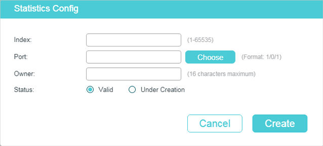
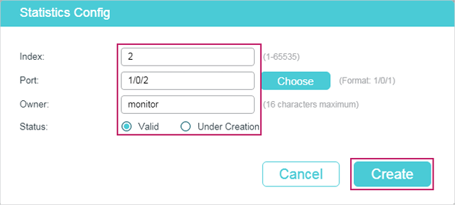
Figure 5-1 Creating a Statistics Entry
Follow these steps to configure the Statistics group:
1)Specify the entry index, the port to be monitored, and the owner name of the entry. Set the entry as Valid or Under Creation.
|
Index |
Enter the index of the entry. |
|
Port |
Click Choose to specify an Ethernet port to be monitored in the entry, or enter the port number in the format of 1/0/1. |
|
Owner |
Enter the owner name of the entry with1 to 16 characters. |
|
Status |
Set the entry as Valid or Under Creation. By default, it is Valid. The switch start to collect Ethernet statistics for a Statistics entry since the entry status is configured as valid. Valid: The entry is created and valid. Under Creation: The entry is created but invalid. |
2)Click Create.
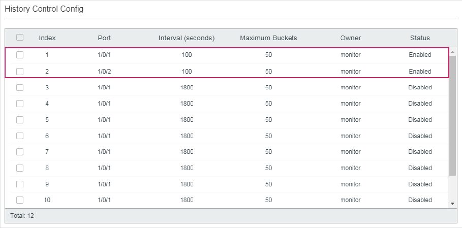
5.1.2Configuring History Group
Choose the menu MAINTENANCE > SNMP > RMON > History to load the following page.
Figure 5-2 Configuring the History Entry
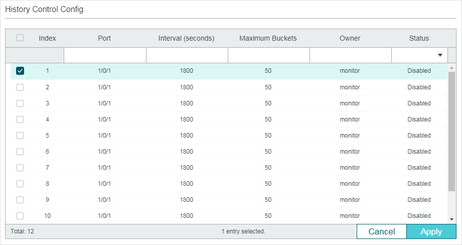
Follow these steps to configure the History group:
1)Select a History entry, and specify a port to be monitored.
|
Index |
Displays the index of History entries. The switch supports up to 12 History entries. |
|
Port |
Specify a port in 1/0/1 format to be monitored. |
2)Set the sample interval and the maximum buckets of History entries.
|
Interval (seconds) |
Specify the number of seconds in each polling cycle. Valid values are from 10 to 3600 seconds and the default is 1800 seconds. Every history entry has its own timer. For the monitored port, the switch samples packet information and generates a record in every interval. |
|
Maximum Buckets |
Set the maximum number of records for the History entry. When the number of records exceeds the limit, the earliest record will be overwritten. Valid values are from 10 to 130 and the default is 50. |
3)Enter the owner name, and set the status of the entry. Click Apply.
|
Owner |
Enter the owner name of the entry with 1 to 16 characters. By default, it is monitor. |
|
Status |
Enable or disable the entry. By default, it is disabled. Enable: The entry is enabled. Disable: The entry is disabled. |
|
|
Note: To change the parameters of a History entry, please enable the entry at the same time, otherwise the change cannot take effect. |
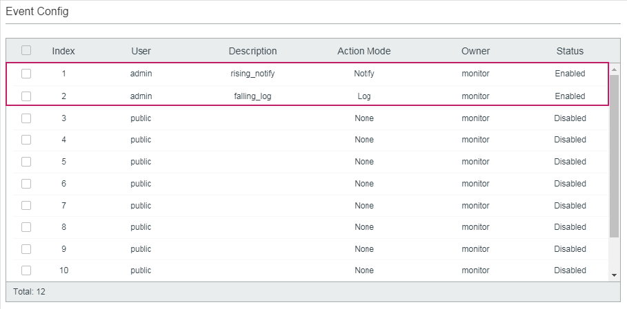
5.1.3Configuring Event Group
Choose the menu MAINTENANCE > SNMP > RMON > Event to load the following page.
Figure 5-3 Configuring the Event Entry
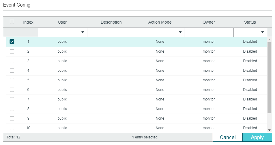
Follow these steps to configure the Event group:
1)Choose an Event entry, and set the SNMP User of the entry.
|
Index |
Displays the index of Event entries. The switch supports up to 12 Event entries. |
|
User |
Choose an SNMP user name or community name for the entry. The name should be the same as what you have set in SNMP previously. |
2)Set the description and action to be taken when the event is triggered.
|
Description |
Enter an brief description of this event to make identifying it easier. |
|
Action Mode |
Specify the action for the switch to take when the event is triggered. None: No action. It is the default setting. Log: The switch records the event in the log, and the NMS should initiate requests to get notifications. Notify: The switch initiates notifications to the NMS. Log & Notify: The switch records the event in the log and sends notifications to the NMS. |
3)Enter the owner name, and set the status of the entry. Click Apply.
|
Owner |
Enter the owner name of the entry with 1 to 16 characters. By default, it is monitor. |
|
Status |
Enable or disable the entry. By default, it is disabled. Enable: The entry is enabled. Disable: The entry is disabled. |
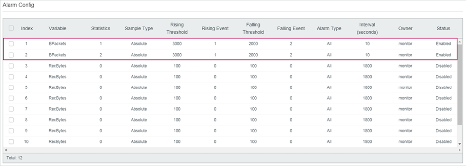
5.1.4Configuring Alarm Group
Before you begin, please complete configurations of Statistics entries and Event entries, because the Alarm entries must be associated with Statistics and Event entries.
Choose the menu MAINTENANCE > SNMP > RMON > Alarm to load the following page.
Figure 5-4 Configuring the Alarm Entry
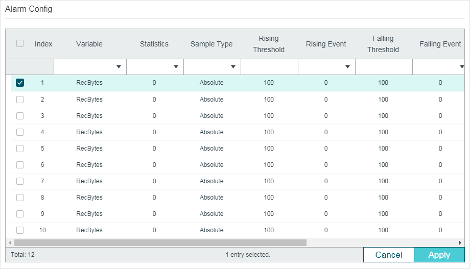
Follow these steps to configure the Alarm group:
1)Select an alarm entry, choose a variable to be monitored, and associate the entry with a statistics entry.
|
Index |
Displays the index of Alarm entries. The switch supports up to 12 Alarm entries. |
|
Variable |
Set the alarm variable to be monitored. The switch will monitor the specified variable in sample intervals and act in the set way when the alarm is triggered. The default variable is RecBytes. RecBytes: Total received bytes. RecPackets: Total received packets. BPackets: Total broadcast packets. MPackets: Total multicast packets. CRC&Align ERR: Packets that range from 64 to 1518 bytes and contain FCS Error or Alignment Error. Undersize: Packets that are smaller than 64 bytes. Oversize: Packets that are larger than 1518 bytes. Jabbers: Packets that are sent when port collisions occur. Collisions: Collision times in the network segment. 64, 65-127, 128-255, 256-511, 512-1023, 1024-10240: Total packets of the specified size. |
|
Statistics |
Associate the Alarm entry with a Statistics entry. Then the switch monitors the specified variable of the Statistics entry. |
2)Set the sample type, the rising and falling threshold, the corresponding event action mode, and the alarm type of the entry.
|
Sample Type |
Set the sampling method of the specified variable; the default is absolute. Absolute: Compare the sampling value against the preset threshold. Delta: The switch obtains the difference between the sampling values of the current interval and the previous interval, and then compares the difference against the preset threshold. |
|
Rising Threshold |
Set the rising threshold of the variable. When the sampled value exceeds the threshold, the system will trigger the corresponding Rising Event. Valid values are from 1 to 2147483647 and the default is 100. |
|
Rising Event |
Specify the index of the Event entry that will be triggered when the sampled value exceeds the preset threshold. The Event entry specified here should be enabled first. |
|
Falling Threshold |
Set the falling threshold of the variable. When the sampled value is below the threshold, the system will trigger the corresponding Falling Event. Valid values are from 1 to 2147483647 and the default is 100. |
|
Falling Event |
Specify the index of the Event entry that will be triggered when the sampled value is below the preset threshold. The Event entry specified here should be enabled first. |
|
Alarm Type |
Specify the alarm type for the entry. By default, the alarm type is all. Rising: The alarm is triggered only when the sampled value exceeds the rising threshold. Falling: The alarm is triggered only when the sampled value is below the falling threshold. All: The alarm is triggered when the sampled value exceeds the rising threshold or is below the falling threshold. |
3)Enter the owner name, and set the status of the entry. Click Apply.
|
Interval (seconds) |
Set the sampling interval. Valid values are from 10 to 3600 seconds and the default is 1800 seconds. |
|
Owner |
Enter the owner name of the entry with 1 to 16 characters. By default, it is monitor. |
|
Status |
Enable or disable the entry. By default, it is disabled. Enable: The entry is enabled. Disable: The entry is disabled. |
5.2Using the CLI
5.2.1Configuring Statistics
|
Step 1 |
configure Enter global configuration mode. |
|
Step 2 |
rmon statistics index interface interface { fastEthernet port | gigabitEthernet port | ten-gigabitEthernet port } [ owner owner-name] [ status { underCreation | valid }] Configure RMON Statistic entries. index: Enter the ID of the statistics entry from 1 to 65535 in the format of 1-3 or 5. port: Enter the port number in 1/0/1 format to bind it to the entry. owner-name: Enter the owner name of the entry with 1 to 16 characters. The default name is monitor. underCreation | valid: Enter the status of the entry. UnderCreation indicates that the entry is created but invalid, while valid indicates the entry is created and valid. By default, it is valid. The switch start to collect Ethernet statistics for a Statistics entry since the entry status is configured as valid. |
|
Step 3 |
show rmon statistics [ index ] Displays the statistics entries and their configurations. index: Enter the index of statistics entries that you want to view. The ranges are from 1 to 65535. |
|
Step 4 |
end Return to privileged EXEC mode. |
|
Step 5 |
copy running-config startup-config Save the settings in the configuration file. |
The following example shows how to create two Statistics entries on the switch to monitor port 1/0/1 and 1/0/2 respectively. The owner of the entries are both monitor and the status are both valid:
Switch#configure
Switch(config)#rmon statistics 1 interface gigabitEthernet 1/0/1 owner monitor status valid
Switch(config)#rmon statistics 2 interface gigabitEthernet 1/0/2 owner monitor status valid
Switch(config)#show rmon statistics
Index Port Owner State
----- ---- ----- -----
1 Gi1/0/1 monitor valid
2 Gi1/0/2 monitor valid
Switch(config)#end
Switch#copy running-config startup-config
5.2.2Configuring History
|
Step 1 |
configure Enter global configuration mode. |
|
Step 2 |
rmon history index interface { fastEthernet port | gigabitEthernet port | ten-gigabitEthernet port } [ interval seconds ] [ owner owner-name ] [ buckets number ] Configuring RMON History entries. index: Enter the index of the History entry from 1 to 12 in the format of 1-3 or 5. port: Enter the port number in 1/0/1 format to bind it to the entry. seconds: Set the sample interval. The values are from 10 to 3600 seconds; the default is 1800 seconds. owner-name: Enter the owner name of the entry with 1 to 16 characters. The default name is monitor. number: Set the maximum number of records for the history entry. When the number of records exceeds the limit, the earliest record will be overwritten. The values are from 10 to 130; the default is 50. |
|
Step 3 |
show rmon history [ index ] Displays the specified History entry and related configurations. index: Enter the index of history entries that you want to view. The range is 1 to 12, and the format is 1-3 or 5. |
|
Step 4 |
end Return to privileged EXEC mode. |
|
Step 5 |
copy running-config startup-config Save the settings in the configuration file. |
The following example shows how to create a History entry on the switch to monitor port 1/0/1. Set the sample interval as 100 seconds, maximum buckets as 50, and the owner as monitor:
Switch#configure
Switch(config)#rmon history 1 interface gigabitEthernet 1/0/1 interval 100 owner monitor buckets 50
Switch(config)#show rmon history
Index Port Interval Buckets Owner State
----- --------- ----------- ----------- --------- -----
1 Gi1/0/1 100 50 monitor Enable
Switch(config)#end
Switch#copy running-config startup-config
5.2.3Configuring Event
|
Step 1 |
configure Enter global configuration mode. |
|
Step 2 |
rmon event index [ user user-name ] [ description description ] [ type { none | log | notify | log-notify }] [ owner owner-name ] Configuring RMON Event entries. index: Enter the index of the Event entry from 1 to12 in the format of 1-3 or 5. user-name: Enter the SNMP user name or community name of the entry. The name should be what you have set in SNMP previously. The default name is public. description: Give a description to the entry with 1 to 16 characters. By default, the description is empty. none | log | notify | log-notify: Specify the action type of the event; then the switch will take the specified action to deal with the event. By default, the type is none. None indicates the switch takes no action, log indicates the switch records the event, notify indicates the switch sends notifications to the NMS, and log-notify indicates the switch records the event and sends notifications to the NMS. owner-name: Enter the owner name of the entry with 1 to 16 characters. The default name is monitor. |
|
Step 3 |
show rmon event [ index ] Displays the specified Event entry and related configurations. index: Enter the index of Event entries that you want to view. The range is 1 to 12, and the format is 1-3 or 5. |
|
Step 4 |
end Return to privileged EXEC mode. |
|
Step 5 |
copy running-config startup-config Save the settings in the configuration file. |
The following example shows how to create an Event entry on the switch. Set the user name as admin, the event type as Notify (set the switch to initiate notifications to the NMS), and the owner as monitor:
Switch#configure
Switch(config)#rmon event 1 user admin description rising-notify type notify owner monitor
Switch(config)#show rmon event
Index User Description Type Owner State
----- ---- ----------- ---- ----- -----
1 admin rising-notify Notify monitor Enable
Switch(config)#end
Switch#copy running-config startup-config
5.2.4Configuring Alarm
|
Step 1 |
configure Enter global configuration mode. |
|
Step 2 |
rmon alarm index stats-index sindex [ alarm-variable { revbyte | revpkt | bpkt | mpkt | crc-align | undersize | oversize | jabber | collision | 64 | 65-127 | 128-255 | 256-511 | 512-1023 | 1024-10240}] [ s-type {absolute | delta}] [ rising-threshold r-hold ] [ rising-event-index r-event ] [ falling-threshold f-hold ] [ falling-event-index f-event ] [ a-type {rise | fall | all} ] [ owner owner-name ] [ interval interval ] Configuring RMON alarm entries. index: Enter the index of the alarm entry from 1 to12 in the format of 1-3 or 5. sindex: Set the index of the related statistics entry from 1 to 65535. revbyte | revpkt | bpkt | mpkt | crc-align | undersize | oversize | jabber | collision | 64 | 65- 127 | 128-255 | 256-511 | 512-1023 | 1024-10240: Choose an alarm variable to monitor. The switch will monitor the specified variable in sample intervals and act in the set way when the alarm is triggered. The default variable is revbyte. revbyte means total received bytes; revpkt means total received packets; bpkt means total broadcast packets. mpkt means total multicast packets; crc-align means packets that range from 64 to 1518 bytes and contain FCS Error or Alignment Error; undersize means packets that are smaller than 64 bytes; oversize means packets that are larger than 1518 bytes; jabber means packets that are sent when port collisions occur; collision means the collision times in the network segment; 64 | 65-127 | 128-255 | 256-511 | 512-1023 | 1024-10240 means total packets of the specified size. absolute | delta: Choose the sampling method of the specified variable. The default is absolute. In the absolute mode, the switch compares the sampling value against the preset threshold; in the delta mode, the switch obtains the difference between the sampling values of the current interval and the previous interval, and then compares the difference against the preset threshold. r-hold: Enter the rising threshold from 1 to 2147483647; the default is 100. r-event: Enter the Event entry index from 1 to 12 to bind it to the rising threshold. The event entry will be triggered when the sampling value exceeds the preset threshold. The Event entry specified here should be enabled first. f-hold: Enter a falling threshold from 1 to 2147483647; the default is 100. |
|
f-event: Enter the Event entry index from 1 to 12 to bind it to the falling threshold. The Event entry will be triggered when the sampling value goes below the preset threshold. The Event entry specified here should be enabled first. rise | fall | all: Choose an alarm type; the default is all. Rise indicates that the alarm is triggered only when the sampled value exceeds the rising threshold. Fall indicates that the alarm is triggered only when the sampled value is below the falling threshold. All indicates that the alarm is triggered when the sampled value exceeds the rising threshold or is below the falling threshold. owner-name: Enter the owner name of the entry using 1 to 16 characters. The default name is monitor. interval: Set the sampling interval. The value ranges from 10 to 3600 seconds; the default is 1800 seconds. |
|
|
Step 3 |
show rmon alarm [ index ] Displays the specified alarm entry and related configurations. index: Enter the index of alarm entries that you want to view. The range is 1 to 12, and the format is 1-3 or 5. |
|
Step 4 |
end Return to privileged EXEC mode. |
|
Step 5 |
copy running-config startup-config Save the settings in the configuration file. |
The following example shows how to set an alarm entry to monitor BPackets on the switch. Set the related Statistics entry ID as 1, the sample type as Absolute, the rising threshold as 3000, the related rising event entry index as 1, the falling threshold as 2000, the related falling event index as 2, the alarm type as all, the notification interval as 10 seconds, and the owner of the entry as monitor:
Switch#configure
Switch(config)#rmon alarm 1 stats-index 1 alarm-variable bpkt s-type absolute rising-threshold 3000 rising-event-index 1 falling-threshold 2000 falling-event-index 2 a-type all interval 10 owner monitor
Switch(config)#show rmon alarm
Index-State: 1-Enabled
Statistics index: 1
Alarm variable: BPkt
Sample Type: Absolute
RHold-REvent: 3000-1
FHold-FEvent: 2000-2
Alarm startup: All
Interval: 10
Owner: monitor
Switch(config)#end
Switch#copy running-config startup-config
6.1Network Requirements
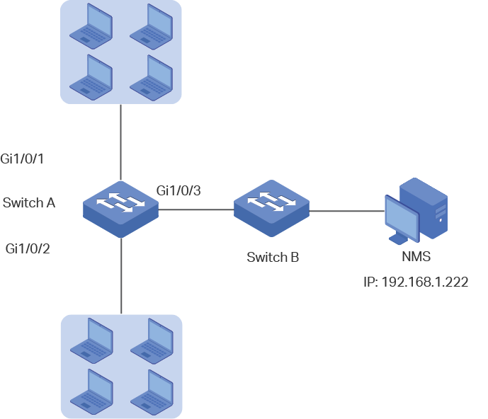
The following figure shows the network topology of a company. The company has requirements as follows:
1)Monitor traffic flow of ports 1/0/1 and 1/0/2 on Switch A, and send notifications to the NMS when the actual rate of transmitting and receiving packets exceeds the preset threshold.
2)Monitor the sending status of ports 1/0/1 and 1/0/2 on Switch A, and regularly collect and save data for follow-up checks. Specifically, during the sample interval, switch A should notify the NMS when the number of packets transmitted and received on the port exceeds the preset threshold; Switch A should record but not notify the NMS when the number of packets transmitted and received is below the threshold.
The NMS host with IP address 192.168.1.222 is connected to the core switch, Switch B. Switch A is connected to Switch B via port 1/0/3. And port 1/0/3 and the NMS are able to reach one another.
Figure 6-1 Network Topology
6.2Configuration Scheme
1)Set a limit on the rate of the specified ports, and then enable SNMP on Switch A. Configure SNMP and Notification, and enable Trap notifications on the ports. Switch A can then send notifications to the NMS when the actual rate exceeds the preset threshold.
2)After SNMP and Notification configurations, you need to create Statistic entries on the ports to monitor the real-time transmitting and receiving of packets and create History entries to regularly collect and save related data. Create two Event entries: one is the notify type used to notify the NMS, the other is the log type used to record related events. In addition, create an Alarm entry to monitor BPackets (Broadcast Packets), set the rising threshold and falling threshold, and bind the rising event to the notify event entry, and the falling event to the log event entry.
Demonstrated with T2600G-28TS, this chapter provides configuration procedures in two ways: using the GUI and using the CLI.
6.3Using the GUI
Configuring Rate Limit on ports
Configure the rate limit on required ports. For detailed configuration, please refer to Configuring QoS_T2600G&T1600G-52TS v3&T1600G-52PS v3 or Configuring QoS_T1500&T1500G&T1600G.
Configuring SNMP
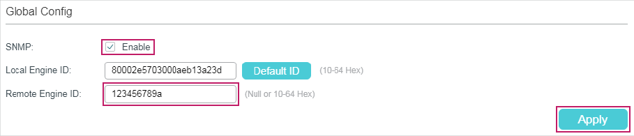
1)Choose MAINTENANCE > SNMP > Global Config to load the following page. In the Global Config section, enable SNMP, and set the Remote Engine ID as 123456789a. Click Apply.
Figure 6-2 Enabling SNMP
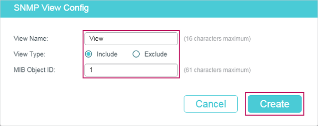
2)In the SNMP View Config section, click to load the following page. Name the SNMP view as View, set the view type as Include, and set MIB Object ID as 1 (which means all functions). Click Create.
Figure 6-3 Creating an SNMP View
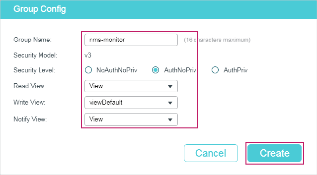
3)Choose MAINTENANCE > SNMP > SNMP v3 > SNMP Group and click to load the following page. Create a group with the name of nms-monitor, enable authentication and privacy, and add View to Read View and Notify View. Click Create.
Figure 6-4 Configuring an SNMP Group
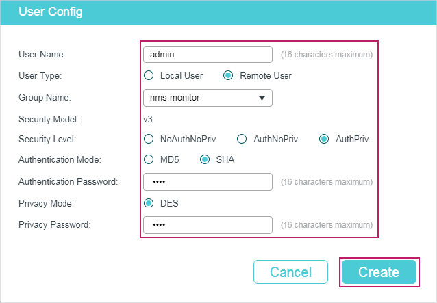
4)Choose MAINTENANCE > SNMP > SNMP v3 > SNMP User and click to load the following page. Create a user named admin for the NMS, set the user type as Remote User and specify the group name. Set the Security Level in accordance with that of the group nms-monitor. Choose SHA authentication algorithm and DES privacy algorithm, and set corresponding passwords. Click Create.
Figure 6-5 Creating an SNMP User
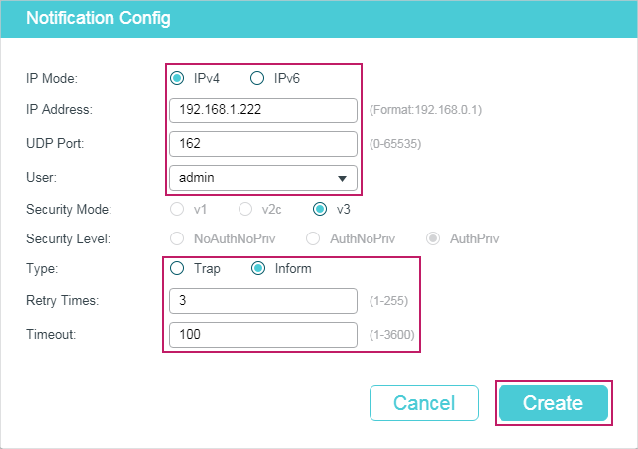
5)Choose MAINTENANCE > SNMP > Notification > Notification Config and click to load the following page. Choose the IP Mode as IPv4, and specify the IP address of the NMS host and the port of the host for transmitting notifications. Specify the User as admin and choose the type as Inform. Set the retry times as 3, with the timeout period as 100 seconds. Click Create.
Figure 6-6 Creating an SNMP Notification Entry
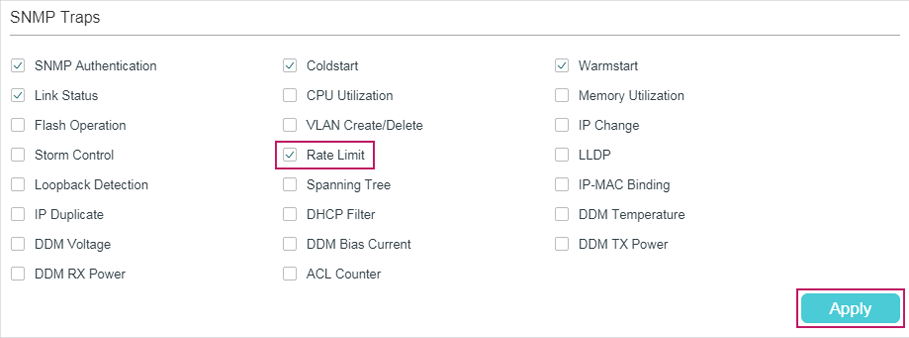
6)Choose MAINTENANCE > SNMP > Notification > Trap Config to load the following page. Enable Rate Limit trap and click Apply.
Figure 6-7 Enabling Rate Limit Trap
7)Click  to save the settings.
Configuring RMON
1)Choose MAINTENANCE > SNMP > RMON > Statistics and click to load the following page. Create two entries and bind them to ports 1/0/1 and 1/0/2 respectively. Set the owner of the entries as monitor and the status as valid.
Figure 6-8 Configuring Statistics Entry 1
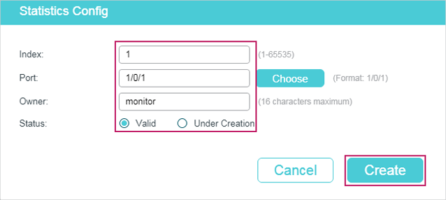
Figure 6-9 Configuring Statistics Entry 2
2)Choose the menu MAINTENANCE > SNMP > RMON > History to load the following page. Configure entries 1 and 2. Bind entries 1 and 2 to ports 1/0/1 and 1/0/2 respectively, and set the Interval as 100 seconds, Maximum Buckets as 50, the owner of the entries as monitor, and the status as Enable.
Figure 6-10 Configuring the History Entries
3)Choose the menu MAINTENANCE > SNMP > RMON > Event to load the following page. Configure entries 1 and 2. For entry 1, set the SNMP user name as admin, type as Notify, description as “rising_notify”, owner as monitor, and status as enable. For entry 2, set the SNMP user name as admin, type as Log, description as “falling_log”, owner as monitor, and status as enable.
Figure 6-11 Configuring the Event Entries
4)Choose MAINTENANCE > SNMP > RMON > Alarm to load the following page. Configure entries 1 and 2. For entry 1, set the alarm variable as BPackets, related statistics entry ID as 1 (bound to port 1/0/1), the sample type as Absolute, the rising threshold as 3000, associated rising event entry ID as 1 (which is the notify type), the falling threshold as 2000, the associated falling event entry ID as 2 (which is the log type), the alarm type as All, the interval as 10 seconds, the owner name as monitor. For entry 2, set the associated statistics entry ID as 2 (bound to port 1/0/2). Other configurations are the same as those of entry 1.
Figure 6-12 Configuring the Alarm Entries
5)Click to save settings.
6.4Using the CLI
Configuring Rate Limit on ports
Configure the rate limit on required ports of Switch A. For detailed configuration, please refer to Configuring QoS_T2600G&T1600G-52TS v3&T1600G-52PS v3 or Configuring QoS_T1500&T1500G&T1600G.
Configuring SNMP
1)Enable SNMP and specify the remote engine ID.
Switch_A#configure
Switch_A(config)#snmp-server
Switch_A(config)#snmp-server engineID remote 123456789a
2)Create a view with the name View; set the MIB Object ID as 1 (which represents all functions), and the view type as Include.
Switch_A(config)#snmp-server view View 1 include
3)Create a group of SNMPv3 with the name of nms-monitor. Enable Auth Mode and Privacy Mode, and set the view as read View and notify view.
Switch_A(config)#snmp-server group nms-monitor smode v3 slev authPriv read View notify View
4)Create an SNMP user with the name admin. Set the user as a remote user and configure the security mode and security level based on the group. Set the Auth Mode as SHA algorithm, password as 1234, the Privacy Mode as DES, and password as 1234.
Switch_A(config)#snmp-server user admin remote nms-monitor smode v3 slev authPriv cmode SHA cpwd 1234 emode DES epwd 1234
5)To configure Notification, specify the IP address of the NMS host and UDP port. Set the User, Security Model and Security Level according to configurations of the SNMP User. Choose the type as Inform, and set the retry times as 3, and the timeout period as 100 seconds.
Switch_A(config)#snmp-server host 192.168.1.222 162 admin smode v3 slev authPriv type inform retries 3 timeout 100
Enable Bandwith-control Trap
Switch_A(config)#snmp-server traps bandwidth-control
Configuring RMON
1)Create two Statistics entries to monitor ports 1/0/1 and 1/0/2 respectively. The owner of the entries is set as monitor, and the status is set as valid.
Switch_A(config)#rmon statistics 1 interface gigabitEthernet 1/0/1 owner monitor status valid
Switch_A(config)#rmon statistics 2 interface gigabitEthernet 1/0/2 owner monitor status valid
2)Create two History entries and bind them to ports 1/0/1 and 1/0/2 respectively. Set the sample interval as 100 seconds, max buckets as 50, and the owner as monitor.
Switch_A(config)#rmon history 1 interface gigabitEthernet 1/0/1 interval 100 owner monitor buckets 50
Switch_A(config)#rmon history 2 interface gigabitEthernet 1/0/2 interval 100 owner monitor buckets 50
3)Create two Event entries named admin, which is the SNMP user name. Set entry 1 as the Notify type and its description as “rising_notify”. Set entry 2 as the Log type and its description as “falling_log”. Set the owner of them as monitor.
Switch_A(config)#rmon event 1 user admin description rising_notify type notify owner monitor
Switch_A(config)#rmon event 2 user admin description falling_log type log owner monitor
4)Create two Alarm entries. For entry 1, set the alarm variable as BPackets, associated Statistics entry ID as 1 (bound to port 1/0/1), the sample type as Absolute, the rising threshold as 3000, the associated rising event entry ID as 1 (Notify type), the falling threshold as 2000, the associated falling event entry ID as 2 (the log type), the alarm type as all, the interval as 10 seconds, and the owner name as monitor. For entry 2, set the associated statistics entry ID as 2 (bound to port 1/0/2), while all other configurations are the same as those of entry 1.
Switch_A(config)#rmon alarm 1 stats-index 1 alarm-variable bpkt s-type absolute rising-threshold 3000 rising-event-index 1 falling-threshold 2000 falling-event-index 2 a-type all interval 10 owner monitor
Switch_A(config)#rmon alarm 2 stats-index 2 alarm-variable bpkt s-type absolute rising-threshold 3000 rising-event-index 1 falling-threshold 2000 falling-event-index 2 a-type all interval 10 owner monitor
Verify the Configurations
Verify global SNMP configurations:
Switch_A(config)#show snmp-server
SNMP agent is enabled.
0 SNMP packets input
0 Bad SNMP version errors
0 Unknown community name
0 Illegal operation for community name supplied
0 Encoding errors
0 Number of requested variables
0 Number of altered variables
0 Get-request PDUs
0 Get-next PDUs
0 Set-request PDUs
0 SNMP packets output
0 Too big errors(Maximum packet size 1500)
0 No such name errors
0 Bad value errors
0 General errors
0 Response PDUs
0 Trap PDUs
Verify SNMP engine ID:
Switch_A(config)#show snmp-server engineID
Local engine ID: 80002e5703000aeb13a23d
Remote engine ID: 123456789a
Verify SNMP view configurations:
Switch_A(config)#show snmp-server view
No. View Name Type MOID
--- -------------- ------- -------------------
1 viewDefault include 1
2 viewDefault exclude 1.3.6.1.6.3.15
3 viewDefault exclude 1.3.6.1.6.3.16
4 viewDefault exclude 1.3.6.1.6.3.18
5 View include 1
Verify SNMP group configurations:
Switch_A(config)#show snmp-server group
No. Name Sec-Mode Sec-Lev Read-View Write-View Notify-View
--- ------------- ----------- ---------- --------------- ------------ ----------
1 nms-monitor v3 authPriv View View
Verify SNMP user configurations:
Switch_A(config)#show snmp-server user
No. U-Name U-Type G-Name S-Mode S-Lev A-Mode P-Mode
--- ----------- ------ ------ ------ ----- ------ ------
1 admin remote nms-monitor v3 authPriv SHA DES
Verify SNMP host configurations:
Switch_A(config)#show snmp-server host
No. Des-IP UDP Name SecMode SecLev Type Retry Timeout
--- ---------------- ----- -------- --------- ---------- ------- ----- --------
1 172.168.1.222 162 admin v3 authPriv inform 3 100
Verify RMON statistics configurations:
Switch_A(config)#show rmon statistics
Index Port Owner State
----- ---------- --------- -------
1 Gi1/0/1 monitor valid
2 Gi1/0/2 monitor valid
Verify RMON history configurations:
Switch_A(config)#show rmon history
Index Port Interval Buckets Owner State
----- --------- -------- --------- ---------- ---------
1 Gi1/0/1 100 50 monitor Enable
2 Gi1/0/2 100 50 monitor Enable
Verify RMON event configurations:
Switch_A(config)#show rmon event
Index User Description Type Owner State
----- ------ ----------- -------- ---------- ----------
1 admin rising-notify Notify monitor Enable
2 admin falling-log Log monitor Enable
Verify RMON alarm configurations:
Switch_A(config)#show rmon alarm
Index-State: 1-Enabled
Statistics index: 1
Alarm variable: BPkt
Sample Type: Absolute
RHold-REvent: 3000-1
FHold-FEvent: 2000-2
Alarm startup: All
Interval: 10
Owner: monitor
Index-State: 2-Enabled
Statistics index: 2
Alarm variable: BPkt
Sample Type: Absolute
RHold-REvent: 3000-1
FHold-FEvent: 2000-2
Alarm startup: All
Interval: 10
Owner: monitor
Default settings of SNMP are listed in the following tables.
Table 7-1Default Global Config Settings
|
Parameter |
Default Setting |
|
SNMP |
Disable |
|
Local Engine ID |
Automatically |
|
Remote Engine ID |
None |
Table 7-2Default SNMP View Table Settings
|
View Name |
View Type |
MIB Object ID |
|
viewDefault |
Include |
1 |
|
viewDefault |
Exclude |
1.3.6.1.6.3.15 |
|
viewDefault |
Exclude |
1.3.6.1.6.3.16 |
|
viewDefault |
Exclude |
1.3.6.1.6.3.18 |
Table 7-3Default SNMP v1/v2c Settings
|
Parameter |
Default Setting |
|
Community Entry |
No entries |
|
Community Name |
None |
|
Access |
Read-only |
|
MIB View |
viewDefault |
Table 7-4Default SNMP v3 Settings
|
Parameter |
Default Setting |
|
SNMP Group |
|
|
Group Entry |
No entries |
|
Group Name |
None |
|
Security Model |
v1 |
|
Security Level |
NoAuthNoPriv |
|
Read View |
viewDefault |
|
Write View |
None |
|
Notify View |
None |
|
SNMP User |
|
|
User Entry |
No entries |
|
User Name |
None |
|
User Type |
Local User |
|
Group Name |
None |
|
Security Model |
v1 |
|
Security Level |
noAuthNoPriv |
|
Authentication Mode |
MD5 (when Security Level is configured as AuthNoPriv or AuthPriv) |
|
Authentication Password |
None |
|
Privacy Mode |
DES (when Security Level is configured as AuthPriv) |
|
Privacy Password |
None |
Default settings of Notification are listed in the following table.
Table 7-5Default Notification Settings
|
Parameter |
Default Setting |
|
Notification Config |
|
|
Notification Entry |
No entries |
|
IP Mode |
IPv4 |
|
IP Address |
None |
|
UDP Port |
162 |
|
User |
None |
|
Security Model |
v1 |
|
Security Level |
noAuthNoPriv |
|
Type |
Trap |
|
Retry |
None in trap mode; 3 times in Inform mode. |
|
Timeout |
None in trap mode; 100 seconds in Inform mode. |
|
Trap Config |
|
|
Enabled SNMP Traps |
SNMP Authentication, Coldstart, Warmstart, Link Status |
Default settings of RMON are listed in the following tables.
Table 7-6Default Statistics Config Settings
|
Parameter |
Default Setting |
|
Statistics Entry |
No entries |
|
ID |
None |
|
Port |
None |
|
Owner |
None |
|
IP Mode |
Valid |
Table 7-7Default Settings for History Entries
|
Parameter |
Default Setting |
|
Port |
1/0/1 |
|
Interval |
1800 seconds |
|
Max Buckets |
50 |
|
Owner |
monitor |
|
Status |
Disable |
Table 7-8Default Settings for Event Entries
|
Parameter |
Default Setting |
|
User |
public |
|
Description |
None |
|
Type |
None |
|
Owner |
monitor |
|
Status |
Disable |
Table 7-9Default Settings for Alarm Entries
|
Parameter |
Default Setting |
|
Variable |
RecBytes |
|
Statistics |
0, means no Statistics entries is selected. |
|
Sample Type |
Absolute |
|
Rising Threshold |
100 |
|
Rising Event |
None |
|
Falling Threshold |
100 |
|
Falling Event |
None |
|
Alarm Type |
All |
|
Interval |
1800 seconds |
|
Owner |
monitor |
|
Status |
Disable |