Configuring QoS
CHAPTERS
2. Class of Service Configuration
3. Bandwidth Control Configuration
|
|
This guide applies to: T1500G-8T v2 or above, T1500G-10PS v2 or above, T1500G-10MPS v2 or above, T1500-28PCT v3 or above, T1600G-18TS v2 or above, T1600G-28TS v3 or above, T1600G-28PS v3 or above, T1600G-52TS v4 or above, T1600G-52PS v4 or above, T2500G-10TS v2 or above, T2600G-18TS v2 or above. To configure T1600G-52TS v3, T1600G-52PS v3, T1700X-16TS v3 or above, T1700G-28TQ v3 or above, T2600G-28TS v3 or above, T2600G-52TS v3 or above, T2600G-28MPS v3 or above, T2600G-28SQ v1 or above, refer to Configuring QoS_T2600G&T1600G-52TS v3&T1600G-52PS v3. |

1.1Overview
With network scale expanding and applications developing, internet traffic is dramatically increased, thus resulting in network congestion, packet drops and long transmission delay. Typically, networks treat all traffic equally on FIFO (First In First Out) delivery basis, but nowadays many special applications like VoD, video conferences, VoIP, etc, require more bandwidth or shorter transmission delay to guarantee the performance.
With QoS (Quality of Service) technology, you can classify and prioritize network traffic to provide differentiated services to certain types of traffic.
1.2Supported Features
You can configure the class of service, bandwidth control, Voice VLAN and Auto VoIP features on the switch to maximize the network performance and bandwidth utilization.
Class of Service
The switch classifies the ingress packets, maps the packets to different priority queues and then forwards the packets according to specified scheduler settings to implement QoS function.
Priority Mode: Three modes are supported, Port Priority, 802.1p Priority and DSCP Priority.
Scheduler Mode: Two scheduler types are supported, Strict and Weighted.
Bandwidth Control
Bandwidth Control functions to control the traffic rate and traffic threshold on each port to ensure network performance.
Rate limit functions to limit the ingress/egress traffic rate on each port. In this way, the network bandwidth can be reasonably distributed and utilized.
Storm Control function allows the switch to monitor broadcast packets, multicast packets and UL-frames (Unknown unicast frames) in the network. If the transmission rate of the packets exceeds the set rate, the packets will be automatically discarded to avoid network broadcast storm.
Voice VLAN and Auto VoIP
The voice VLAN and Auto VoIP features are used to prioritize the transmission of voice traffic. Voice traffic is typically more time-sensitive than data traffic, and the voice quality can deteriorate a lot because of packet loss and delay. To ensure the high voice quality, you can configure Voice VLAN or Auto VoIP.
These two features can be enabled on the ports that transmit voice traffic only or transmit both voice traffic and data traffic. Voice VLAN can change the voice packets’ 802.1p priority and transmit the packets in desired VLAN. Auto VoIP can inform the voice devices of send the packets with specific configuration by working with the LLDP-MED feature.
2Class of Service Configuration
With class of service configurations, you can:
Configure port priority
Configure 802.1p priority
Configure DSCP priority
Specify the scheduler settings
Configuration Guidelines
Select the priority mode that the ports trust according to your network requirements.
A port can use only one priority to classify the ingress packets. Three priority modes are supported on the switch: Port Priority, 802.1P Priority and DSCP Priority.
»Port Priority
In this mode, the switch prioritizes packets according to their ingress ports, regardless of the packet field or type.
»802.1P Priority
802.1P defines the first three bits in 802.1Q Tag as PRI field. The PRI values are from 0 to 7. 802.1P priority determines the priority of packets based on the PRI value.
In this mode, the switch only prioritizes packets with VLAN tag, regardless of the IP header of the packets.
»DSCP Priority
DSCP priority determines the priority of packets based on the ToS (Type of Service) field in their IP header. RFC2474 re-defines the ToS field in the IP packet header as DS field. The first six bits (bit 0-bit 5) of the DS field is used to represent DSCP priority. The DSCP values are from 0 to 63.
In this mode, the switch only prioritizes IP packets.
Specify the 802.1p to queue mapping according to your needs.
For 802.1p Priority, the packets will be forwarded according to the 802.1p to queue mapping directly.
For Port Priority and DSCP Priority, the port priority and DSCP priority will first be mapped to the 802.1p priority, and then mapped to the queue according to the 802.1p to queue mapping.
2.1Using the GUI
2.1.1Configuring Port Priority
Configuring the Trust Mode and Port to 802.1p Mapping
Choose the menu QoS > Class of Service > Port Priority to load the following page.
Figure 2-1 Configuring the Trust Mode and Port to 802.1p Mapping
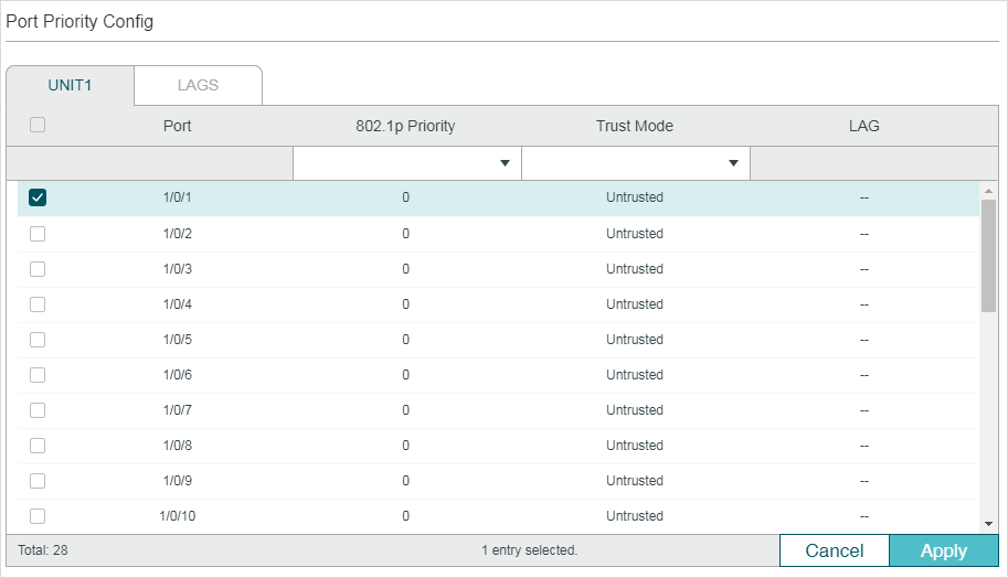
Follow these steps to configure the parameters of the port priority:
1)Select the desired ports, specify the 802.1p priority and set the trust mode as Untrusted.
|
802.1p Priority |
Specify the port to 802.1p mapping for the desired port. The ingress packets from one port are first mapped to 802.1p priority based on the port to 802.1p mapping, then to TC queues based on the 802.1p to queue mapping. The untagged packets from one port will be added an 802.1p priority value according to the port to 802.1p priority mapping. |
|
Trust Mode |
Select the Trust mode as Untrusted. In this mode, the packets will be processed according to the port priority configuration. |
2)Click Apply.
Configuring the 802.1p to Queue Mapping
Choose the menu QoS > Class of Service > 802.1p Priority to load the following page.
Figure 2-2 Configuring the 802.1p to Queue Mapping
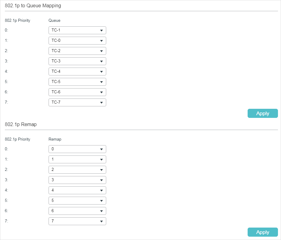
In the 802.1p to Queue Mapping section, configure the mappings and click Apply.
|
802.1p Priority |
Displays the number of 802.1p priority. In QoS, 802.1p priority is used to represent class of service. |
|
Queue |
Select the TC queue for the desired 802.1p priority. The packets with the desired 802.1p priority will be put in the corresponding queue. |
2.1.2Configuring 802.1p Priority
Configuring the Trust Mode
Choose the menu QoS > Class of Service > Port Priority to load the following page.
Figure 2-3 Configuring the Trust Mode
Follow these steps to configure the trust mode:
1)Select the desired ports and set the trust mode as Trust 802.1p.
|
Trust Mode |
Select the Trust mode as Trust 802.1p. In this mode, the tagged packets will be processed according to the 802.1p priority configuration and the untagged packets will be processed according to the port priority configuration. |
2)Click Apply.
Configuring the 802.1p to Queue Mapping and 802.1p Remap
Choose the menu QoS > Class of Service > 802.1p Priority to load the following page.
Figure 2-4 Configuring the 802.1p to Queue Mapping and 802.1p Remap
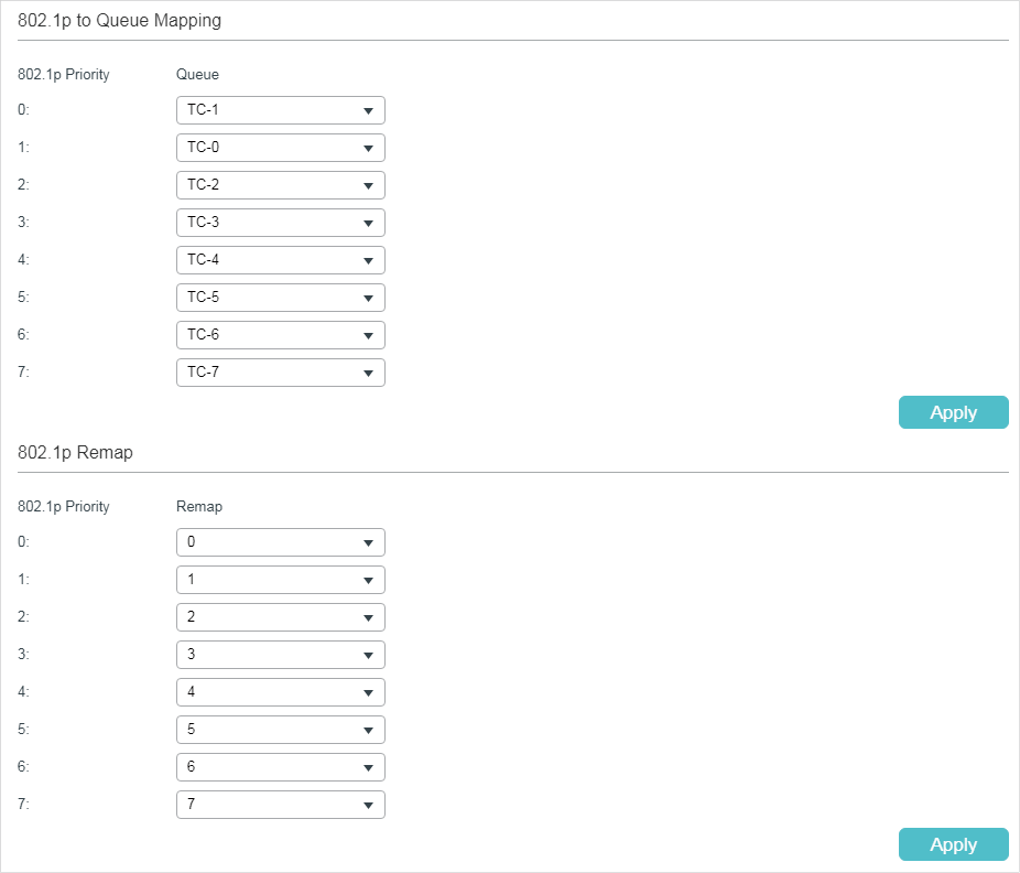
Follow these steps to configure the parameters of the 802.1p priority:
1)In the 802.1p to Queue Mapping section, configure the mappings and click Apply.
|
802.1p Priority |
Displays the number of 802.1p priority. In QoS, 802.1p priority is used to represent class of service. IEEE 802.1p standard defines three bits in 802.1Q tag as PRI filed. The PRI values are called 802.1p priority and used to represent the priority of the layer 2 packets. This function requires packets with VLAN tags. |
|
Queue |
Select the TC queue for the desired 802.1p priority. The packets with the desired 802.1p priority will be put in the corresponding queue. |
2)(Optional) In the 802.1p Remap section, configure the 802.1p to 802.1p mappings and click Apply.
|
802.1p Priority |
Displays the number of 802.1p priority. In QoS, 802.1p priority is used to represent class of service. IEEE 802.1p standard defines three bits in 802.1Q tag as PRI filed. The PRI values are called 802.1p priority and used to represent the priority of the layer 2 packets. This function requires packets with VLAN tags. |
|
Remap |
Select the number of 802.1p priority to which the original 802.1p priority will be remapped. 802.1p Remap is used to modify the 802.1p priority of the ingress packets. When the switch detects the packets with desired 802.1p priority, it will modify the value of 802.1p priority according to the map. |
|
|
Note: In Trust 802.1p mode, the untagged packets will be added an 802.1p priority based on the port to 802.1p mapping and will be forwarded according to the 802.1p to queue mapping. |

2.1.3Configuring DSCP Priority
Configuring the Trust Mode
Choose the menu QoS > Class of Service > Port Priority to load the following page.
Figure 2-5 Configuring the Trust Mode
Follow these steps to configure the trust mode:
1)Select the desired ports and set the trust mode as Trust DSCP.
|
Trust Mode |
Select the Trust mode as Trust DSCP. In this mode, the IP packets will be processed according to the DSCP priority configuration and the non-IP packets will be processed according to the port priority configuration. |
2)Click Apply.
Configuring the 802.1p to Queue Mapping
Choose the menu QoS > Class of Service > 802.1p Priority to load the following page.
Figure 2-6 Configuring the 802.1p to Queue Mapping
In the 802.1p to Queue Mapping section, configure the mappings and click Apply.
|
802.1p Priority |
Displays the number of 802.1p priority. In QoS, 802.1p priority is used to represent class of service. |
|
Queue |
Select the TC queue for the desired 802.1p priority. The packets with the desired 802.1p priority will be put in the corresponding queue. |
Configuring the DSCP to 802.1p Mapping and the DSCP Remap
Choose the menu QoS > Class of Service >DSCP Priority to load the following page.
Figure 2-7 Configuring the DSCP to 802.1p Mapping and the DSCP Remap
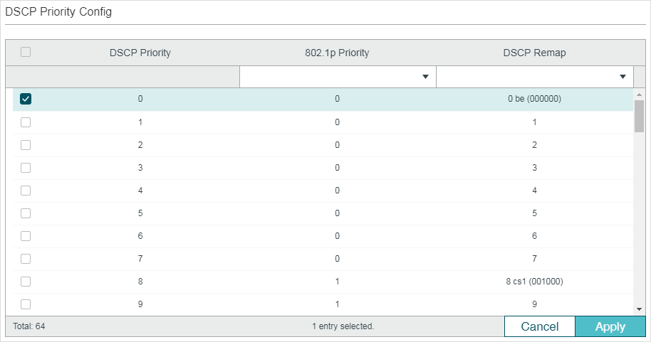
Follow these steps to configure the DSCP Priority:
1)In the DSCP Priority Config section, configure the DSCP to 802.1p mapping and the DSCP remap.
|
DSCP Priority |
Displays the number of DSCP priority. DSCP Priority is used to classify the packets based on the value of DSCP, and map them to different queues. ToS (Type of Service) is a part of IP header, and DSCP uses the first six bits of ToS to represent the priority of IP packets. The DSCP values range from 0 to 63. |
|
802.1p Priority |
Specify the DSCP to 802.1p mapping. The ingress packets are first mapped to 802.1p priority based on the DSCP to 802.1p mappings, then to TC queues according to the 802.1p to queue mappings. The untagged IP packets with the desired DSCP value will be added an 802.1p priority value according to the DSCP to 802.1p mapping. |
|
DSCP Remap |
(Optional) Select the DSCP priority to which the original DSCP priority will be remapped. When the switch detects the packets with desired DSCP value, it will modify the packets’ DSCP value according to the map. |
2)Click Apply.
|
|
Note: In Trust DSCP mode, non-IP packets will be added an 802.1p priority based on the port to 802.1p mapping and will be forwarded according to the 802.1p to queue mapping. |
2.1.4Specifying the Scheduler Settings
Specify the scheduler settings to control the forwarding sequence of different TC queues when congestion occurs.
Choose the menu QoS > Class of Service > Scheduler Settings to load the following page.
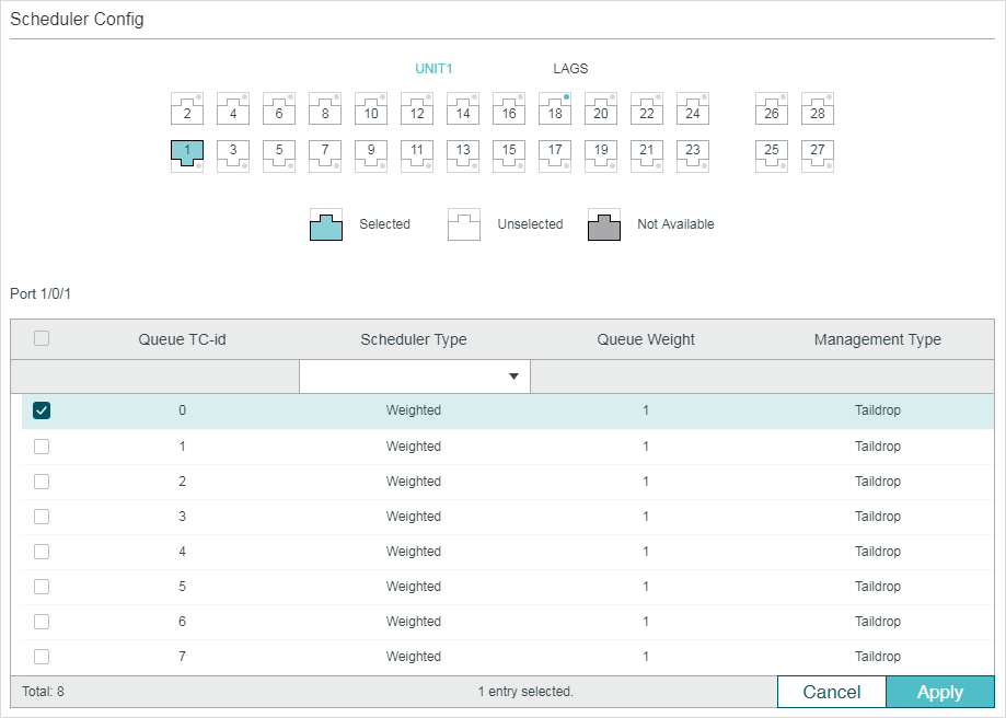
Figure 2-8 Specifying the Scheduler Settings
Follow these steps to configure the schedule mode:
1)In the Scheduler Config section, select the desired port.
2)Select the desired queue and configure the parameters.
|
Queue TC-id |
Displays the ID number of priority Queue. |
|
Scheduler Type |
Select the type of scheduling used for corresponding queue. When the network congestion occurs, the egress queue will determine the forwarding sequence of the packets according to the type. Strict: In this mode, the egress queue will use SP (Strict Priority) to process the traffic in different queues. When congestion occurs, the traffic will be transmitted according to its queue priority strictly. The queue with higher priority occupies the whole bandwidth. Packets in the queue with lower priority are sent only when the queue with higher priority is empty. Weighted: In this mode, the egress queue will use WRR (Weighted Round Robin) to process the traffic in different queues. When congestion occurs, all the traffic will be transmitted, but the bandwidth that each traffic queue occupies will be allocated based on the queue weight. |
|
Queue Weight |
Specify the queue weight for the desired queue. This value can be set only in the Weighted mode. The valid values are from 1 to 127. |
|
Management Type |
Displays the Management Type for the queues. The switch supports Taildrop mode. When the traffic exceeds the limit, the additional traffic will be dropped. |
3)Click Apply.
|
|
Note: With ACL Redirect feature, the switch maps all the packets that meet the configured ACL rules to the new TC queue, regardless of the mapping relations configured in this section. |

2.2.1Configuring Port Priority
Configuring the Trust Mode and the port to 802.1p Mapping
Follow these steps to configure the trust mode and the port to 802.1p mapping:
|
Step 1 |
configure Enter global configuration mode |
|
Step 2 |
interface {fastEthernet port | range fastEthernet port-list | gigabitEthernet port | range gigabitEthernet port-list | ten-gigabitEthernet port | range ten-gigabitEthernet port-list | port-channel port-channel-id | range port-channel port-channel-list} Enter interface configuration mode. |
|
Step 3 |
qos trust mode {untrust | dot1p | dscp} Select the trust mode for the port. By default, it is untrust. Here we set the trust mode as untrust. untrust: Specify the ports’ trust mode as untrust. In this mode, the packets will be processed according to the port priority configuration. |
|
Step 4 |
qos port-priority {dot1p-priority} Specify the port to 802.1p priority mapping for the desired port. The ingress packets from one port are first mapped to 802.1p priority based on the port to 802.1p mapping, then to TC queues based on the 802.1p to queue mapping. The untagged packets from one port will be added an 802.1p priority value according to the port to 802.1p mapping. dot1p-priority: Specify the 802.1p priority ranging from 0 to 7. The default value is 0. |
|
Step 5 |
show qos trust interface [fastEthernet port | gigabitEthernet port | ten-gigabitEthernet port | port-channel port-channel-id] Verify the trust mode of the ports. |
|
Step 6 |
show qos port-priority interface [fastEthernet port | gigabitEthernet port | ten-gigabitEthernet port | port-channel port-channel-id] Verify the port to 802.1p mappings. |
|
Step 7 |
end Return to privileged EXEC mode. |
|
Step 8 |
copy running-config startup-config Save the settings in the configuration file. |
Configuring the 802.1p to Queue Mapping
Follow these steps to configure the 802.1p to queue mapping:
|
Step 1 |
configure Enter global configuration mode |
|
Step 2 |
qos cos-map {dot1p-priority} {tc-queue} Specify the 802.1p to queue mapping. The packets with the desired 802.1p priority will be put in the corresponding queues. By default, the 802.1p priority 0 to 7 is respectively mapped to TC-1, TC-0, TC-2, TC-3, TC-4, TC-5, TC-6, TC-7. dot1p-priority: Specify the 802.1p priority. The valid values are from 0 to 7. tc-queue: Specify the ID number of the TC queue. The valid values are from 0 to 7. |
|
Step 3 |
show qos cos-map Verify the 802.1p to queue mappings. |
|
Step 4 |
end Return to privileged EXEC mode. |
|
Step 5 |
copy running-config startup-config Save the settings in the configuration file. |
The following example shows how to configure the trust mode of port 1/0/1 as untrust, map the port 1/0/1 to 802.1p priority 1 and map 802.1p priority 1 to TC3:
Switch#configure
Switch(config)#interface gigabitEthernet 1/0/1
Switch(config-if)#qos trust mode untrust
Switch(config-if)#qos port-priority 1
Switch(config-if)#exit
Switch(config)#qos cos-map 1 3
Switch(config)#show qos trust interface gigabitEthernet 1/0/1
Port Trust Mode LAG
-------- --------- --------
Gi1/0/1 untrust N/A
Switch(config)#show qos port-priority interface gigabitEthernet 1/0/1
Port CoS Value LAG
-------- --------- --------
Gi1/0/1 CoS 1 N/A
Switch(config)#show qos cos-map
---------------+-----+-----+-----+-----+-----+-----+----+----
Dot1p Value |0 |1 |2 |3 |4 |5 |6 |7
---------------+-----+-----+-----+-----+-----+-----+----+----
TC |TC0 |TC3 |TC2 |TC3 |TC4 |TC5 |TC6 |TC7
---------------+-----+-----+-----+-----+-----+-----+----+----
Switch(config)#end
Switch#copy running-config startup-config
2.2.2Configuring 802.1p Priority
Configuring the Trust Mode
Follow these steps to configure the trust mode:
|
Step 1 |
configure Enter global configuration mode |
|
Step 2 |
interface {fastEthernet port | range fastEthernet port-list | gigabitEthernet port | range gigabitEthernet port-list | ten-gigabitEthernet port | range ten-gigabitEthernet port-list | port-channel port-channel-id | range port-channel port-channel-list} Enter interface configuration mode. |
|
Step 3 |
qos trust mode {untrust | dot1p | dscp} Select the trust mode for the port. By default, it is untrust. Here we set the trust mode as dot1p. dot1p: Specify the ports’ trust mode as dot1p. In this mode, the tagged packets will be processed according to the 802.1p priority configuration and the untagged packets will be processed according to the port priority configuration. |
|
Step 4 |
show qos trust interface [fastEthernet port | gigabitEthernet port | ten-gigabitEthernet port | port-channel port-channel-id] Verify the trust mode of the ports. |
|
Step 5 |
end Return to privileged EXEC mode. |
|
Step 6 |
copy running-config startup-config Save the settings in the configuration file. |
Configuring the 802.1p to Queue Mapping and 802.1p Remap
Follow these steps to configure the 802.1p to queue mapping and 802.1p remap:
|
Step 1 |
configure Enter global configuration mode |
|
Step 2 |
qos cos-map {dot1p-priority} {tc-queue} Specify the 802.1p to queue mapping. The packets with the desired 802.1p priority will be put in the corresponding queues. By default, the 802.1p priority 0 to 7 is respectively mapped to TC-1, TC-0, TC-2, TC-3, TC-4, TC-5, TC-6, TC-7. dot1p-priority: Specify the 802.1p priority. The valid values are from 0 to 7. tc-queue: Specify the ID number of the TC queue. The valid values are from 0 to 7. |
|
Step 3 |
qos dot1p-remap {dot1p-priority} {new-dot1p-priority} (Optional) Specify the 802.1p to 802.1p mappings. 802.1p Remap is used to modify the 802.1p priority of the ingress packets. When the switch detects the packets with desired 802.1p priority, it will modify the value of 802.1p priority according to the map. By default, the original 802.1p priority 0 is mapped to the 802.1p priority 0, the original 802.1p priority 1 is mapped to the 802.1p priority 1 and so on. dot1p-priority: Specify the original 802.1p priority. The valid values are from 0 to 7. new-dot1p-priority: Specify the new 802.1p priority. The valid values are from 0 to 7. |
|
Step 4 |
show qos cos-map Verify the 802.1p to queue mappings. |
|
Step 5 |
show qos dot1p-remap Verify the 802.1p to 802.1p mappings. |
|
Step 6 |
end Return to privileged EXEC mode. |
|
Step 7 |
copy running-config startup-config Save the settings in the configuration file. |
|
|
Note: In Trust 802.1p mode, the untagged packets will be added an 802.1p priority based on the port to 802.1p mapping and will be forwarded according to the 802.1p to queue mapping. |
The following example shows how to configure the trust mode of port 1/0/1 as dot1p, map 802.1p priority 3 to TC4, and configure to map the original 802.1p 1 to 802.1p priority 3:
Switch#configure
Switch(config)#interface gigabitEthernet 1/0/1
Switch(config-if)#qos trust mode dot1p
Switch(config-if)#exit
Switch(config)#qos cos-map 3 4
Switch(config)#qos dot1p-remap 1 3
Switch(config)#show qos trust interface gigabitEthernet 1/0/1
Port Trust Mode LAG
-------- --------- --------
Gi1/0/1 trust 802.1P N/A
Switch(config)#show qos cos-map
---------------+-----+-----+-----+-----+-----+-----+----+----
Dot1p Value |0 |1 |2 |3 |4 |5 |6 |7
---------------+-----+-----+-----+-----+-----+-----+----+----
TC |TC0 |TC1 |TC2 |TC4 |TC4 |TC5 |TC6 |TC7
---------------+-----+-----+-----+-----+-----+-----+----+----
Switch(config)#show qos dot1p-remap
Dot1p Value 0 1 2 3 4 5 6 7 LAG
----- ----- ----- ----- ----- ----- ----- ----- -----
Dot1p Remap 0 3 2 3 4 5 6 7 N/A
Switch(config)#end
Switch#copy running-config startup-config
2.2.3Configuring DSCP Priority
Configuring the Trust Mode
Follow these steps to configure the trust mode:
|
Step 1 |
configure Enter global configuration mode |
|
Step 2 |
interface {fastEthernet port | range fastEthernet port-list | gigabitEthernet port | range gigabitEthernet port-list | ten-gigabitEthernet port | range ten-gigabitEthernet port-list | port-channel port-channel-id | range port-channel port-channel-list} Enter interface configuration mode. |
|
Step 3 |
qos trust mode {untrust | dot1p | dscp} Select the trust mode for the port. By default, it is untrust. Here we set the trust mode as dscp. dscp: Specify the ports’ trust mode as dscp. In this mode, the IP packets will be processed according to the DSCP priority configuration and the non-IP packets will be processed according to the port priority configuration. |
|
Step 4 |
show qos trust interface [fastEthernet port | gigabitEthernet port | ten-gigabitEthernet port | port-channel port-channel-id] Verify the trust mode of the ports. |
|
Step 5 |
end Return to privileged EXEC mode. |
|
Step 6 |
copy running-config startup-config Save the settings in the configuration file. |
Configuring the 802.1p to Queue Mapping
Follow these steps to configure the 802.1p to queue mapping:
|
Step 1 |
configure Enter global configuration mode |
|
Step 2 |
qos cos-map {dot1p-priority} {tc-queue} Specify the 802.1p to queue mapping. The packets with the desired 802.1p priority will be put in the corresponding queues. By default, the 802.1p priority 0 to 7 is respectively mapped to TC-1, TC-0, TC-2, TC-3, TC-4, TC-5, TC-6, TC-7. dot1p-priority: Specify the 802.1p priority. The valid values are from 0 to 7. tc-queue: Specify the ID number of the TC queue. The valid values are from 0 to 7. |
|
Step 3 |
show qos cos-map Verify the 802.1p to queue mappings. |
|
Step 4 |
end Return to privileged EXEC mode. |
|
Step 5 |
copy running-config startup-config Save the settings in the configuration file. |
Configuring the DSCP to 802.1p Mapping and DSCP Remp
Follow these steps to configure the DSCP to 802.1p mapping and DSCP remap:
|
Step 1 |
configure Enter global configuration mode |
|
Step 2 |
qos dscp-map {dscp-value-list} {dot1p-priority} Specify the DSCP to 802.1p mapping. The ingress packets with the desired DSCP priority are first mapped to 802.1p priority based on the DSCP to 802.1p mapping, then to TC queues based on the 802.1p to queue mapping. The untagged packets with the desired DSCP priority will be added an 802.1p priority value according to the DSCP to 802.1p mapping. by default, the DSCP priorities 0-7 are mapped to the 802.1p priority 0, the DSCP priorities 8-15 are mapped to the 802.1p priority 1 and so on. dscp-value-list: Specify the DSCP value list in the format of “1-3,5,7”. The valid values are from 0 to 63. dot1p-priority: Specify the 802.1p priority. The valid values are from 0 to 7. |
|
Step 3 |
qos dscp-remap {dscp-value-list} {dscp-remap-value} (Optional) Specify the DSCP to DSCP mappings. DSCP Remap is used to modify the DSCP priority of the ingress packets. When the switch detects the packets with the desired DSCP priority, it will modify the value of DSCP priority according to the map. By default, the original DSCP priority 0 is mapped to the DSCP priority 0, the original DSCP priority 1 is mapped to the DSCP priority 1 and so on. dscp-value-list: Specify the original DSCP priority list in the format of “1-3,5,7”. The valid values are from 0 to 63. dscp-remap-value: Specify the new DSCP priority. The valid values are from 0 to 63. |
|
Step 4 |
show qos dscp-map Verify the DSCP to queue mappings. |
|
Step 5 |
show qos dscp-remap Verify the DSCP to DSCP mappings. |
|
Step 6 |
end Return to privileged EXEC mode. |
|
Step 7 |
copy running-config startup-config Save the settings in the configuration file. |
|
|
Note: In Trust DSCP mode, non-IP packets will be added an 802.1p priority based on the port to 802.1p mapping and will be forwarded according to the 802.1p to queue mapping. |
The following example shows how to configure the trust mode of port 1/0/1 as dscp, map 802.1p priority 3 to TC4, map DSCP priority 1-3,5,7 to 802.1p priority 3, and configure to map the original DSCP priority 9 to DSCP priority 5:
Switch#configure
Switch(config)#interface gigabitEthernet 1/0/1
Switch(config-if)#qos trust mode dscp
Switch(config-if)#exit
Switch(config)#qos cos-map 3 4
Switch(config)#qos dscp-map 1-3,5,7 3
Switch(config)#qos dscp-remap 9 5
Switch(config)#show qos trust interface gigabitEthernet 1/0/1
Port Trust Mode LAG
-------- --------- ------
Gi1/0/1 trust DSCP N/A
Switch(config)#show qos cos-map
---------------+-----+-----+-----+-----+-----+-----+----+----
Dot1p Value |0 |1 |2 |3 |4 |5 |6 |7
---------------+-----+-----+-----+-----+-----+-----+----+----
TC |TC0 |TC1 |TC2 |TC4 |TC4 |TC5 |TC6 |TC7
---------------+-----+-----+-----+-----+-----+-----+----+----
Switch(config)#show qos dscp-map
DSCP: 0 1 2 3 4 5 6 7
DSCP to 802.1P 0 3 3 3 0 3 0 3
---- ---- ---- ---- ---- ---- ---- ----
DSCP: 8 9 10 11 12 13 14 15
DSCP to 802.1P 1 1 1 1 1 1 1 1
---- ---- ---- ---- ---- ---- ---- ----
DSCP: 16 17 18 19 20 21 22 23
DSCP to 802.1P 2 2 2 2 2 2 2 2
---- ---- ---- ---- ---- ---- ---- ----
DSCP: 24 25 26 27 28 29 30 31
DSCP to 802.1P 3 3 3 3 3 3 3 3
---- ---- ---- ---- ---- ---- ---- ----
DSCP: 32 33 34 35 36 37 38 39
DSCP to 802.1P 4 4 4 4 4 4 4 4
---- ---- ---- ---- ---- ---- ---- ----
DSCP: 40 41 42 43 44 45 46 47
DSCP to 802.1P 5 5 5 5 5 5 5 5
---- ---- ---- ---- ---- ---- ---- ---
DSCP: 48 49 50 51 52 53 54 55
DSCP to 802.1P 6 6 6 6 6 6 6 6
---- ---- ---- ---- ---- ---- ---- ----
DSCP: 56 57 58 59 60 61 62 63
DSCP to 802.1P 7 7 7 7 7 7 7 7
---- ---- ---- ---- ---- ---- ---- ---
Switch(config)#show qos dscp-remap
DSCP: 0 1 2 3 4 5 6 7
DSCP remap value 0 1 2 3 4 5 6 7
---- ---- ---- ---- ---- ---- ---- ----
DSCP: 8 9 10 11 12 13 14 15
DSCP remap value 8 5 10 11 12 13 14 15
---- ---- ---- ---- ---- ---- ---- ----
DSCP: 16 17 18 19 20 21 22 23
DSCP remap value 16 17 18 19 20 21 22 23
---- ---- ---- ---- ---- ---- ---- ----
DSCP: 24 25 26 27 28 29 30 31
DSCP remap value 24 25 26 27 28 29 30 31
---- ---- ---- ---- ---- ---- ---- ----
DSCP: 32 33 34 35 36 37 38 39
DSCP remap value 32 33 34 35 36 37 38 39
---- ---- ---- ---- ---- ---- ---- ----
DSCP: 40 41 42 43 44 45 46 47
DSCP remap value 40 41 42 43 44 45 46 47
---- ---- ---- ---- ---- ---- ---- ----
DSCP: 48 49 50 51 52 53 54 55
DSCP remap value 48 49 50 51 52 53 54 55
---- ---- ---- ---- ---- ---- ---- ----
DSCP: 56 57 58 59 60 61 62 63
DSCP remap value 56 57 58 59 60 61 62 63
---- ---- ---- ---- ---- ---- ---- ----
Switch(config-if)#end
Switch#copy running-config startup-config
2.2.4Specifying the Scheduler Settings
Follow these steps to specify the scheduler settings to control the forwarding sequence of different TC queues when congestion occurs.
|
Step 1 |
configure Enter global configuration mode. |
|
Step 2 |
interface {fastEthernet port | range fastEthernet port-list | gigabitEthernet port | range gigabitEthernet port-list | ten-gigabitEthernet port | range ten-gigabitEthernet port-list | port-channel port-channel-id | range port-channel port-channel-list} Enter interface configuration mode. |
|
Step 3 |
qos queue tc-queue mode {sp | wrr} [weight weight] Specify the type of scheduling used for corresponding queue. When the network congestion occurs, the egress queue will determine the forwarding sequence of the packets according to the type. By default, it is wrr mode and the all the queue weights are 1. tc-queue: Specify the ID number of TC queue. The valid values are from 0 to 7. sp: In sp mode, the egress queue will use SP (Strict Priority) to process the traffic in different queues. When congestion occurs, the traffic will be transmitted according to its queue priority strictly. The queue with higher priority occupies the whole bandwidth. Packets in the queue with lower priority are sent only when the queue with higher priority is empty. wrr: In wrr mode, the egress queue will use WRR (Weighted Round Robin) to process the traffic in different queues. When congestion occurs, all the traffic will be transmitted, but the bandwidth that each traffic queue occupies will be allocated based on the queue weight. weight: Specify the queue weight for the desired queue. This value can be set only in the wrr mode. The valid values are from 1 to 127. |
|
Step 4 |
show qos queue interface [fastEthernet port | gigabitEthernet port | ten-gigabitEthernet port | port-channel port-channel-id] Verify the scheduler settings.. |
|
Step 5 |
end Return to privileged EXEC mode. |
|
Step 6 |
copy running-config startup-config Save the settings in the configuration file. |
|
|
Note: With ACL Redirect feature, the switch maps all the packets that meet the configured ACL rules to the new TC queue, regardless of the mapping relations configured in this section. |
The following example shows how to specify the scheduler settings for port 1/0/1. Set the scheduler mode of TC1 as sp mode, set the scheduler mode of TC4 as wrr mode and set the queue weight as 5.
Switch#configure
Switch(config)#interface gigabitEthernet 1/0/1
Switch(config-if)#qos queue 1 mode sp
Switch(config-if)#qos queue 4 mode wrr weight 5
Switch(config-if)#show qos queue interface gigabitEthernet 1/0/1
Gi1/0/1----LAG: N/A
Queue Schedule Mode Weight
----- ---------- -----
TC0 WRR 1
TC1 Strict N/A
TC2 WRR 1
TC3 WRR 1
TC4 WRR 5
TC5 WRR 1
TC6 WRR 1
TC7 WRR 1
Switch(config-if)#end
Switch#copy running-config startup-config
3Bandwidth Control Configuration
With bandwidth control configurations, you can:
Configure rate limit
Configure storm control
3.1.1Configuring Rate Limit
Choose the menu QoS > Bandwidth Control > Rate Limit to load the following page.
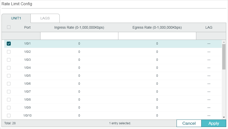
Figure 3-1 Configuring Rate Limit
Follow these steps to configure the Rate Limit function:
1)Select the desired port and configure the upper rate limit to receive and send packets.
|
Ingress Rate (0-1,000,000Kbps) |
Configure the upper rate limit for receiving packets on the port. The valid values are from 0 to 1000000 Kbps and 0 means the ingress rate limit is disabled. |
|
Egress Rate (0-1,000,000Kbps) |
Configure the bandwidth for sending packets on the port. The valid values are from 0 to 1000000 Kbps and 0 means the egress rate limit is disabled. |
2)Click Apply.
3.1.2Configuring Storm Control
Choose the menu QoS > Bandwidth Control > Storm Control to load the following page.
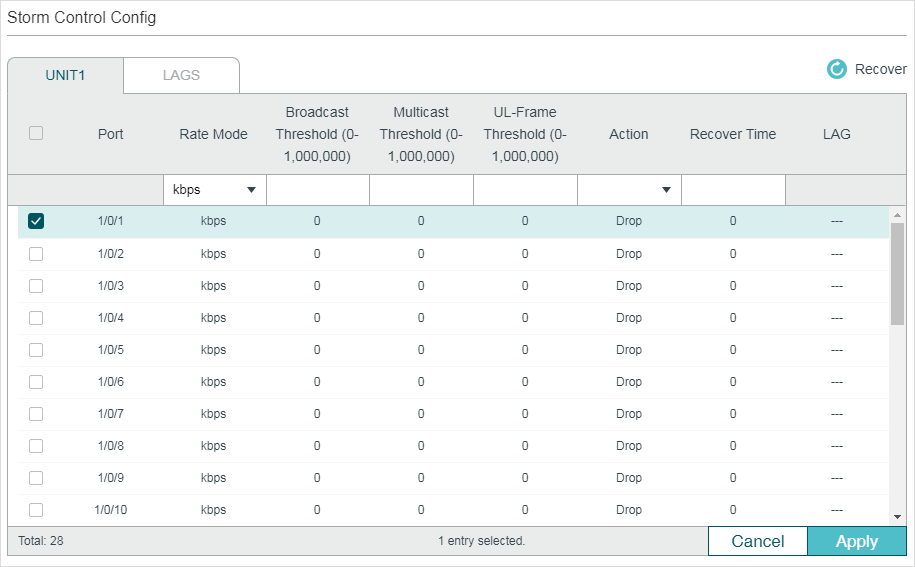
Figure 3-2 Configuring Storm Control
Follow these steps to configure the Storm Control function:
1)Select the desired port and configure the upper rate limit for forwarding broadcast packets, multicast packets and UL-frames (Unknown unicast frames).
|
Rate Mode |
Specify the Rate Mode for the broadcast threshold, multicast threshold and UL-Frame threshold on the desired port. kbps: The switch will limit the maximum speed of the specific kinds of traffic in kilo-bits per second. ratio: The switch will limit the percentage of bandwidth utilization for specific kinds of traffic. |
|
Broadcast Threshold (0-1,000,000) |
Specify the upper rate limit for receiving broadcast packets. The valid values differ among different rate modes. The value 0 means the broadcast threshold is disabled. The broadcast traffic exceeding the limit will be processed according to the Action configurations. |
|
Multicast Threshold (0-1,000,000) |
Specify the upper rate limit for receiving multicast packets. The valid values differ among different rate modes. The value 0 means the multicast threshold is disabled. The multicast traffic exceeding the limit will be processed according to the Action configurations. |
|
UL-Frame Threshold (0-1,000,000) |
Specify the upper rate limit for receiving unknown unicast frames. The valid values differ among different rate modes. The value 0 means the unknown unicast threshold is disabled. The traffic exceeding the limit will be processed according to the Action configurations. |
|
Action |
Select the action that the switch will take when the traffic exceeds its corresponding limit. Drop: Set the Action as Drop. The port will drop the subsequent packets when the traffic exceeds the limit. Shutdown: Set the Action as Shutdown. The port will be shutdown when the traffic exceeds the limit. |
|
Recover Time |
Specify the recover time for the port. It takes effect only when the action is set as shutdown. The valid values are from 0 to 3600 seconds. When the port is shutdown, it can recover to its normal state after the recover time passed. If the recover time is specified as 0, which means the port will not recover to its normal state automatically and you can recover the port manually. |
2)Click Apply.
3.2.1Configuring Rate Limit
Follow these steps to configure the upper rate limit for the port to receive and send packets:
|
Step 1 |
configure Enter global configuration mode. |
|
Step 2 |
interface {fastEthernet port | range fastEthernet port-list | gigabitEthernet port | range gigabitEthernet port-list | ten-gigabitEthernet port | range ten-gigabitEthernet port-list | port-channel port-channel-id | range port-channel port-channel-list} Enter interface configuration mode. |
|
Step 3 |
bandwidth {ingress ingress-rate | egress egress-rate} Configure the upper rate limit for the port to receive and send packets. ingress-rate: Configure the upper rate limit for receiving packets on the port. The valid values are from 0 to 1000000 Kbps. egress-rate: Configure the upper rate limit for sending packets on the port. The valid values are from 0 to 1000000 Kbps. |
|
Step 4 |
show bandwidth interface [fastEthernet port | gigabitEthernet port | ten-gigabitEthernet port | port-channel port-channel-id] Verify the ingress/egress rate limit for forwarding packets on the port or LAG. If no port or LAG is specified, it displays the upper ingress/egress rate limit for all ports or LAGs. |
|
Step 5 |
end Return to privileged EXEC mode. |
|
Step 6 |
copy running-config startup-config Save the settings in the configuration file. |
The following example shows how to configure the ingress-rate as 5120 Kbps and egress-rate as 1024 Kbps for port 1/0/5:
Switch#configure
Switch(config)#interface gigabitEthernet 1/0/5
Switch(config-if)#bandwidth ingress 5120 egress 1024
Switch(config-if)#show bandwidth interface gigabitEthernet 1/0/5
Port IngressRate(Kbps) EgressRate(Kbps) LAG
--------- ---------------------- ---------------------- ------------
Gi1/0/5 5120 1024 N/A
Switch(config-if)#end
Switch#copy running-config startup-config
3.2.2Configuring Storm Control
Follow these steps to configure the upper rate limit on the port for forwarding broadcast packets, multicast packets and unknown unicast frames:
|
Step 1 |
configure Enter global configuration mode |
|
Step 2 |
interface {fastEthernet port | range fastEthernet port-list | gigabitEthernet port | range gigabitEthernet port-list | ten-gigabitEthernet port | range ten-gigabitEthernet port-list | port-channel port-channel-id | range port-channel port-channel-list} Enter interface configuration mode. |
|
Step 3 |
storm-control rate-mode {kbps | ratio} Specify the Rate Mode for the broadcast threshold, multicast threshold and UL-Frame threshold on the desired port. kbps: The switch will limit the maximum speed of the specific kinds of traffic in kilo-bits per second. ratio: The switch will limit the percentage of bandwidth utilization for specific kinds of traffic. |
|
Step 4 |
storm-control broadcast rate Specify the upper rate limit for receiving broadcast packets. The broadcast traffic exceeding the limit will be processed according to the Action configurations. rate: Enter the upper rate. In kbps mode, the valid values are from 1 to 1000000 Kbps. In ratio mode, the valid values are from 1 to100 percent. |
|
Step 5 |
storm-control multicast rate Specify the upper rate limit for receiving multicast packets. The multicast traffic exceeding the limit will be processed according to the Action configurations. rate: Enter the upper rate. In kbps mode, the valid values are from 1 to 1000000 Kbps. In ratio mode, the valid values are from 1 to100 percent. |
|
Step6 |
storm-control unicast rate Specify the upper rate limit for receiving unknown unicast frames. The traffic exceeding the limit will be processed according to the Action configurations. rate: Enter the upper rate. In kbps mode, the valid values are from 1 to 1000000 Kbps. In ratio mode, the valid values are from 1 to100 percent. |
|
Step 7 |
storm-control exceed {drop | shutdown} [recover-time time] Specify the action and the recover time. The switch will perform the action when the traffic exceeds its corresponding limit. By default, it is drop. drop: Set the Action as Drop. The port will drop the subsequent packets when the traffic exceeds the limit. shutdown: Set the Action as Shutdown. The port will be shutdown when the traffic exceeds the limit. time: Specify the recover time for the port. It takes effect only when the action is set as shutdown. The valid values are from 0 to 3600 and the default value is 0. When the port is shutdown, it can recover to its normal state after the recover time passed. If the recover time is specified as 0, which means the port will not recover to its normal state automatically and you can recover the port manually. |
|
Step 8 |
storm-control recover (Optional) Recover the port manually. When the recover time is specified as 0, the port will not recover to its normal state automatically. In this condition, you need to use this command to recover the port manually. |
|
Step 9 |
show storm-control interface [fastEthernet port | gigabitEthernet port | ten-gigabitEthernet port | port-channel port-channel-id] Verify the storm control configurations of the port or LAG. If no port or LAG is specified, it displays the storm control configuration for all ports or LAGs. |
|
Step 10 |
end Return to privileged EXEC mode. |
|
Step 11 |
copy running-config startup-config Save the settings in the configuration file. |
The following example shows how to configure the upper rate limit of broadcast packets as 1024 kbps, Specify the action as shutdown and set the recover time as 10 for port 1/0/5:
Switch#configure
Switch(config)#interface gigabitEthernet 1/0/5
T2600G-28TS(config-if)#storm-control rate-mode kbps
T2600G-28TS(config-if)#storm-control broadcast 1024
T2600G-28TS(config-if)#storm-control exceed shutdown recover-time 10
T2600G-28TS(config-if)#show storm-control interface gigabitEthernet 1/0/5
Port Rate Mode BcRate McRate UlRate Exceed Recover Time LAG
------- ---------- -------- -------- -------- --------- -------- ------
Gi1/0/5 kbps 1024 0 0 shutdown 10 N/A
Switch(config-if)#end
Switch#copy running-config startup-config
To complete the voice VLAN configurations, follow these steps:
1)Create a 802.1Q VLAN
2)Configure OUI addresses
3)Configure Voice VLAN globally
4)Add ports to Voice VLAN
Configuration Guidelines
Before configuring voice VLAN, you need to create a 802.1Q VLAN for voice traffic. For details about 802.1Q VLAN Configuration, please refer to Configuring 802.1Q VLAN.
VLAN 1 is a default VLAN and cannot be configured as the voice VLAN.
Only one VLAN can be set as the voice VLAN on the switch.
4.1.1Configuring OUI Addresses
The OUI address is assigned as a unique identifier by IEEE (Institute of Electrical and Electronics Engineers) to a device vendor. It is used by the switch to determine whether a packet is a voice packet.
If the OUI address of your voice device is not in the OUI table, you need to add the OUI address to the table.
Choose the menu QoS > Voice VLAN > OUI Config to load the following page.
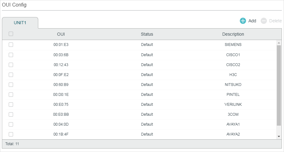
Figure 4-1 Configuring OUI Addresses
Follow these steps to configure the OUI addresses:
1)Click  to load the following page.
Figure 4-2 Creating an OUI Entry
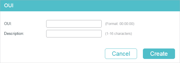
2)Specify the OUI and the Description.
|
OUI |
Enter the OUI address of your voice devices. The OUI address is used by the switch to determine whether a packet is a voice packet. An OUI address is the first 24 bits of a MAC address, and is assigned as a unique identifier by IEEE (Institute of Electrical and Electronics Engineers) to a device vendor. If the source MAC address of a packet matches the OUI addresses in the OUI list, the switch identifies the packet as a voice packet and prioritizes it in transmission. |
|
Description |
Give an OUI address description for identification. |
3)Click Create.
4.1.1Configuring Voice VLAN Globally
Choose the menu QoS > Voice VLAN > Global Config to load the following page.
Figure 4-3 Configuring Voice VLAN Globally
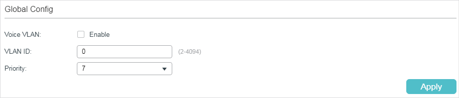
Follow these steps to configure voice VLAN globally:
1)Enable the voice VLAN feature and specify the parameters.
|
VLAN ID |
Specify the 802.1Q VLAN ID to set the 802.1Q VLAN as the voice VLAN. |
|
Priority |
Select the priority that will be assigned to voice packets. A bigger value means a higher priority. This is an IEEE 802.1p priority, and you can further configure its scheduler mode in Class of Service if needed. |
2)Click Apply.
4.1.1Adding Ports to Voice VLAN
Choose the menu QoS > Voice VLAN > Port Config to load the following page.
Figure 4-4 Adding Ports to Voice VLAN
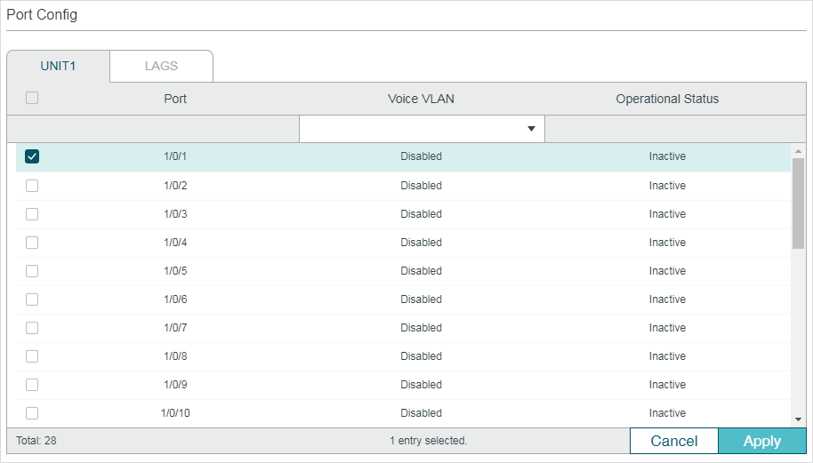
Follow these steps to configure voice VLAN globally:
1)Select the desired ports and choose Enable in Voice VLAN filed.
|
Voice VLAN |
Select Enable to enable the voice VLAN feature on ports and add the desired ports to Voice VLAN. |
|
Optional Status |
Displays the state of the Voice VLAN on the corresponding port. Active: Indicates that Voive VLAN function is enabled on the port. Inactive: Indicates that Voive VLAN function is disabled on the port. |
2)Click Apply.
Follow these steps to configure voice VLAN:
|
Step 1 |
configure Enter global configuration mode. |
|
Step 2 |
show voice vlan oui-table Check whether the OUI address of your voice device is in the OUI table. The OUI address is used by the switch to determine whether a packet is a voice packet. An OUI address is the first 24 bits of a MAC address, and is assigned as a unique identifier by IEEE (Institute of Electrical and Electronics Engineers) to a device vendor. If the source MAC address of a packet matches the OUI addresses in the OUI list, the switch identifies the packet as a voice packet and prioritizes it in transmission. |
|
Step 3 |
voice vlan oui oui-prefix oui-desc string If the OUI address of your voice device is not in the OUI table, add the OUI address to the table. oui-prefix: Enter the OUI address for your voice device in the format of XX:XX:XX. string: Give an OUI address description for identification. It contains 16 characters at most. |
|
Step 4 |
voice vlan vid Enable the voice VLAN feature and specify an existing 802.1Q VLAN as the voice VLAN. vid: Enter the 802.1Q VLAN ID to set the 802.1Q VLAN as the voice VLAN. |
|
Step 5 |
voice vlan priority pri Specify the priority that will be assigned to voice packets. pri: Enter the priority that will be assigned to voice packets. A bigger value means a higher priority. The valid values are from 0 to 7 and the default value is 7. This is an IEEE 802.1p priority, and you can further configure its scheduler mode in Class of Service if needed. |
|
Step 6 |
interface {fastEthernet port | range fastEthernet port-list | gigabitEthernet port | range gigabitEthernet port-list | ten-gigabitEthernet port | range ten-gigabitEthernet port-list | port-channel port-channel-id | range port-channel port-channel-list} Enter interface configuration mode. |
|
Step 7 |
voice vlan Enable the voice VLAN feature on ports and add the desired ports to voice VLAN. |
|
Step 8 |
show voice vlan interface Verify the voice VLAN configuration information. |
|
Step 8 |
end Return to privileged EXEC mode. |
|
Step 9 |
copy running-config startup-config Save the settings in the configuration file. |
The following example shows how to show the OUI table, set VLAN 8 as voice VLAN, set the priority as 6 and enable voice VLAN feature on port 1/0/3:
Switch#configure
Switch(config)#show voice vlan oui-table
00:01:E3 Default SIEMENS
00:03:6B Default CISCO1
00:12:43 Default CISCO2
00:0F:E2 Default H3C
00:60:B9 Default NITSUKO
00:D0:1E Default PINTEL
00:E0:75 Default VERILINK
00:E0:BB Default 3COM
00:04:0D Default AVAYA1
00:1B:4F Default AVAYA2
00:04:13 Default SNOM
Switch(config)#voice vlan 8
Switch(config)#voice vlan priority 6
Switch(config)#interface gigabitEthernet 1/0/3
Switch(config-if)#voice vlan
Switch(config-if)#show voice vlan interface
Voice VLAN ID 8
Priority 6
Interface Voice VLAN Mode Operational Status LAG
--------- --------------- ------------------ ---
Gi1/0/1 disabled Down N/A
Gi1/0/2 disabled Down N/A
Gi1/0/3 enabled Up N/A
Gi1/0/4 disabled Down N/A
Gi1/0/5 disabled Down N/A
......
Switch(config-if)#end
Switch#copy running-config startup-config
Configuration Guidelines
Before configuring Auto VoIP, you need to enable LLDP-MED on ports and configure the relevant parameters. For details about LLDP-MED configuration, please refer to Configuring LLDP.
Auto VoIP provide flexible solutions for optimizing the voice traffic. It can work with other features such as VLAN and Class of Service to process the voice packets with specific fields. You can choose and configure Auto VoIP and other features according to your needs.
Choose the menu QoS > Auto VoIP to load the following page.
Figure 5-1 Configuring Auto VoIP
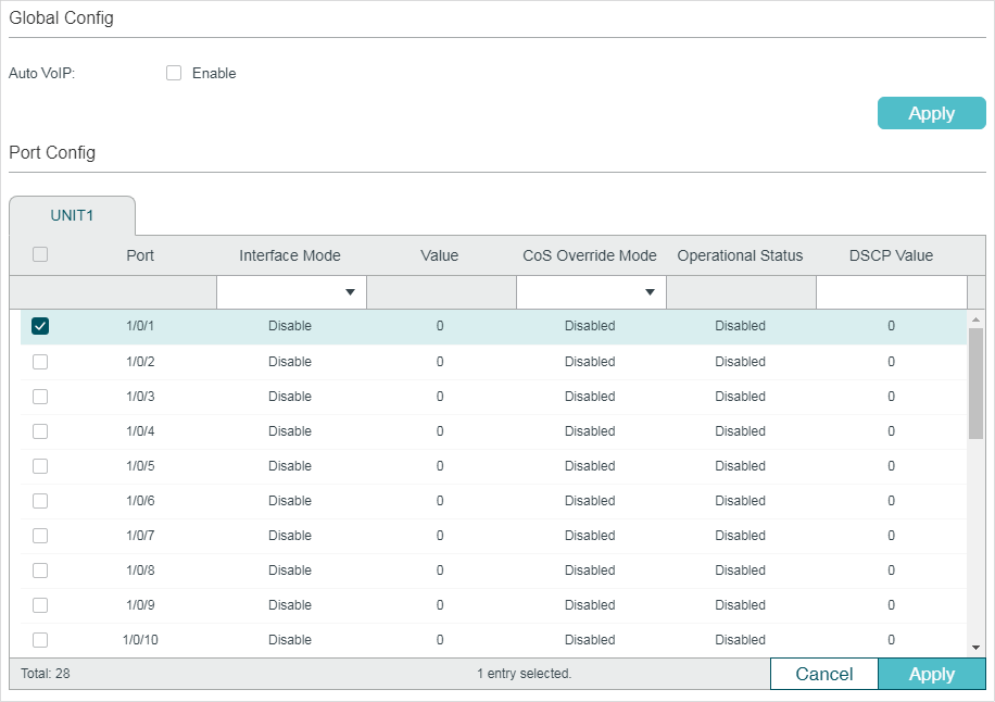
Follow these steps to configure the OUI addresses:
1)In the Global Config section, enable the Auto VoIP function gloablly.
2)In the Port Config section, select the desired and configure the parameters.
|
Interface Mode |
Select the interface mode for the port. Disable: Disable the Auto VoIP function on the corresponding port. None: Allow the voice devices to use its own configuration to send voice traffic. VLAN ID: The voice devices will send voice packets with desired VLAN tag. If this mode is selected, it is necessary to specify the VLAN ID in the Value field. In addition, you need to configure the 802.1Q VLAN to ensure the corresponding ports can forward the packets normally. Dot1p: The voice devices will send voice packets with desired 802.1p priority. If this mode is selected, it is necessary to specify 802.1p priority in the Value field. In addition, you can configure the Class of Service to make the switch process the packets according to the 802.1p priority. Untagged: The voice devices will send untagged voice packets. |
|
Value |
Enter the value of VLAN ID or 802.1p priority for the port according to the Interface Mode configurations. |
|
CoS Override Mode |
Enable or disable the Class of Service override mode. Enabled: Enable CoS override. The switch will ignore the 802.1p priority in the voice packets and put the packets in TC-5 directly. Disabled: Disable CoS override. The switch will then put the voice packets in the corresponding TC queue according to the 802.1p priority of the packets. |
|
Operational Status |
Displays the operating status of the Voice VLAN feature on the interface. To make it enabled, you must enable the Voice VLAN both globally and on the interface. |
|
DSCP Value |
Enter the value of DSCP priority. The voice device will send the packets with the corresponding DSCP value. In addition, you can configure the Class of Service to make the switch process the packets according to the DSCP priority. |
3)Click Apply.
Follow these steps to configure Auto VoIP:
|
Step 1 |
configure Enter global configuration mode. |
|
Step 2 |
auto-voip Enable Auto VoIP globally. |
|
Step 3 |
interface {fastEthernet port | range fastEthernet port-list | gigabitEthernet port | range gigabitEthernet port-list | ten-gigabitEthernet port | range ten-gigabitEthernet port-list | port-channel port-channel-id | range port-channel port-channel-list} Enter interface configuration mode. |
|
Step 4 |
Select the interface mode for the port. no auto-voip Specify the interface mode as disabled, which means the Auto VoIP function is disabled on the corresponding port. auto-voip none Specify the interface mode as none. In this mode, the switch allows the voice devices to use its own configuration to send voice traffic. auto-voip vlan-id Specify the interface mode as VLAN ID. In this mode, the voice devices will send voice packets with desired VLAN tag. If this mode is selected, it is necessary to specify the 802.1Q VLAN ID. The valid values are from 1 to 4093. In addition, you need to configure the 802.1Q VLAN to ensure the corresponding ports can forward the packets normally. auto-voip dot1p dot1p Specify the interface mode as dot1p. In this mode, the voice devices will send voice packets with desired 802.1p priority. If this mode is selected, it is necessary to specify 802.1p priority. The valid values are from 0 to 7. In addition, you can configure the Class of Service to make the switch process the packets according to the 802.1p priority. auto-voip untagged Specify the interface mode as untagged. In this mode, the voice devices will send untagged voice packets. |
|
Step 5 |
auto-voip data priority {trust | untrust} Enable or disable the Class of Service override mode. By default, it is trust, which means the Class of Service override mode is disabled. trust: In this mode, the switch will then put the voice packets in the corresponding TC queue according to the 802.1p priority of the packets. untrust: In this mode, the switch will ignore the 802.1p priority in the voice packets and put the packets in TC-5 directly. |
|
Step 6 |
auto-voip dscp value Specify the value of DSCP priority. The voice device will send the packets with the corresponding DSCP value. In addition, you can configure the Class of Service to make the switch process the packets according to the DSCP priority. value: Enter the value of DSCP priority. The valid values are from 0 to 63 and the default value is 0. |
|
Step 7 |
show auto-voip Verify the global state of Auto VoIP. |
|
Step 8 |
show auto-voip interface Verify the Auto VoIP configuration information of ports. |
|
Step 8 |
end Return to privileged EXEC mode. |
|
Step 9 |
copy running-config startup-config Save the settings in the configuration file. |
The following example shows how to set the interface mode as dot1p, specify the 802.1p priority as 4, specify the DSCP priority as 10 and enable the CoS override mode for port 1/0/3:
Switch#configure
Switch(config)#auto-voip
Switch(config)#interface gigabitEthernet 1/0/3
Switch(config-if)#auto-voip dot1p 4
Switch(config-if)#auto-voip dscp 10
Switch(config-if)#auto-voip data priority untrust
Switch(config-if)#show auto-voip
Administrative Mode: Enabled
Switch(config-if)#show auto-voip interface
Interface.Gi1/0/1
Auto-VoIP Interface Mode. Disabled
Auto-VoIP COS Override. False
Auto-VoIP DSCP Value. 0
Auto-VoIP Port Status. Disabled
Interface.Gi1/0/2
Auto-VoIP Interface Mode. Disabled
Auto-VoIP COS Override. False
Auto-VoIP DSCP Value. 0
Auto-VoIP Port Status. Disabled
Interface.Gi1/0/3
Auto-VoIP Interface Mode. Enabled
Auto-VoIP Priority. 4
Auto-VoIP COS Override. True
Auto-VoIP DSCP Value. 10
Auto-VoIP Port Status. Enabled
......
Switch(config-if)#end
Switch#copy running-config startup-config
6.1Example for Class of Service
6.1.1Network Requirements
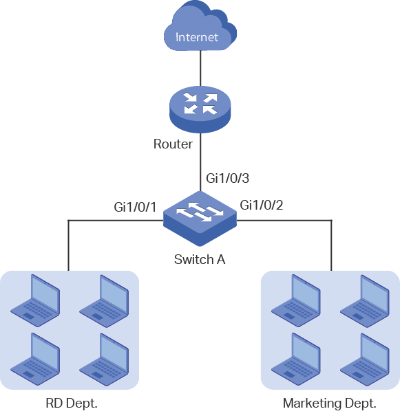
As shown below, both RD department and Marketing department can access the internet. When congestion occurs, the traffic from two departments can both be forwarded and the traffic from the Marketing department should take precedence.
Figure 6-1 QoS Application Topology
6.1.2Configuration Scheme
To implement this requirement, you can configure Port Priority to put the packets from the Marketing department into the queue with the higher priority than the packets from the RD department.
1)Configure the trust mode of port 1/0/1 and port 1/0/2 as untrusted and map the ports to different queues.
2)Set the scheduler type of the queues as weighted for port 1/0/3 and specify the queue weight to make the traffic from the Marketing department take precedence.
Demonstrated with T2600G-28TS, the following sections provide configuration procedure in two ways: using the GUI and using the CLI.
6.1.3Using the GUI
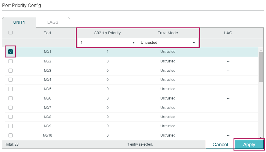
1)Choose the menu QoS > Class of Service > Port Priority to load the following page. Set the trust mode of port 1/0/1 and 1/0/2 as untrusted. Specify the 802.1p priority of port 1/0/1 as 1 and specify the 802.1p priority of port 1/0/2 as 0. Click Apply.
Figure 6-2 Configuring Port Priority
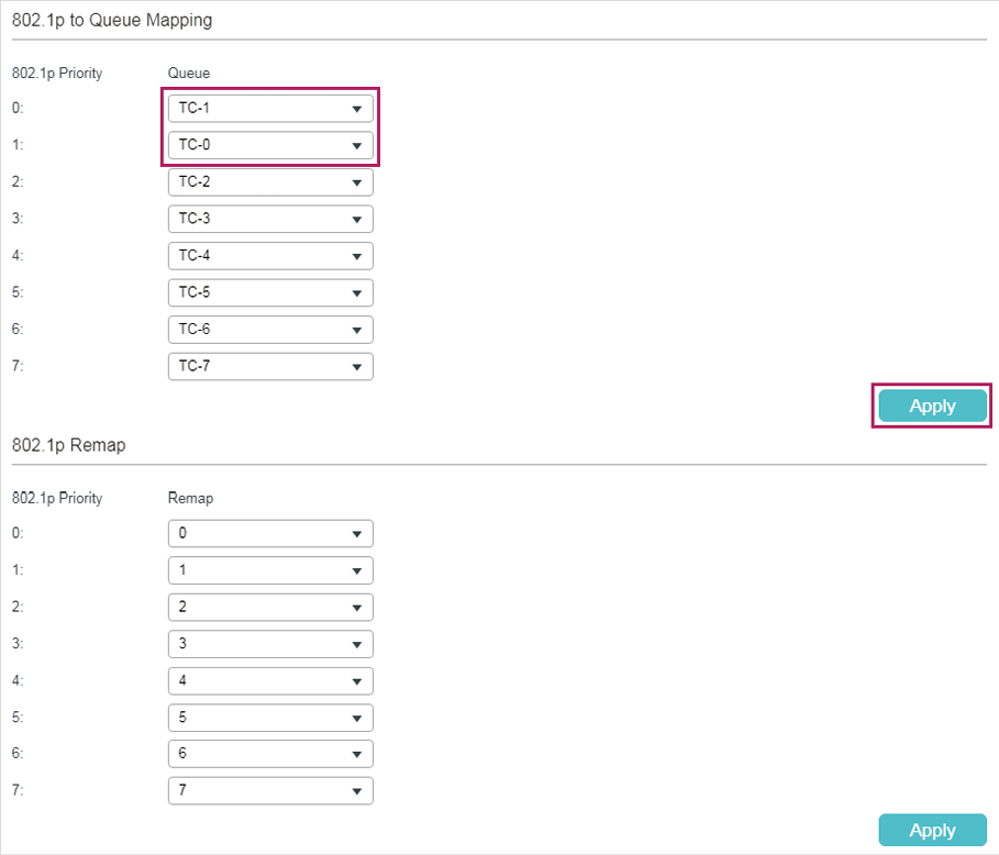
2)Choose the menu QoS > Class of Service > 802.1p Priority to load the following page. Map the 802.1p priority 0 to TC-1 and map the 802.1p priority 1 to TC-0. Click Apply.
Figure 6-3 Configuring the 802.1p to Queue Mappings
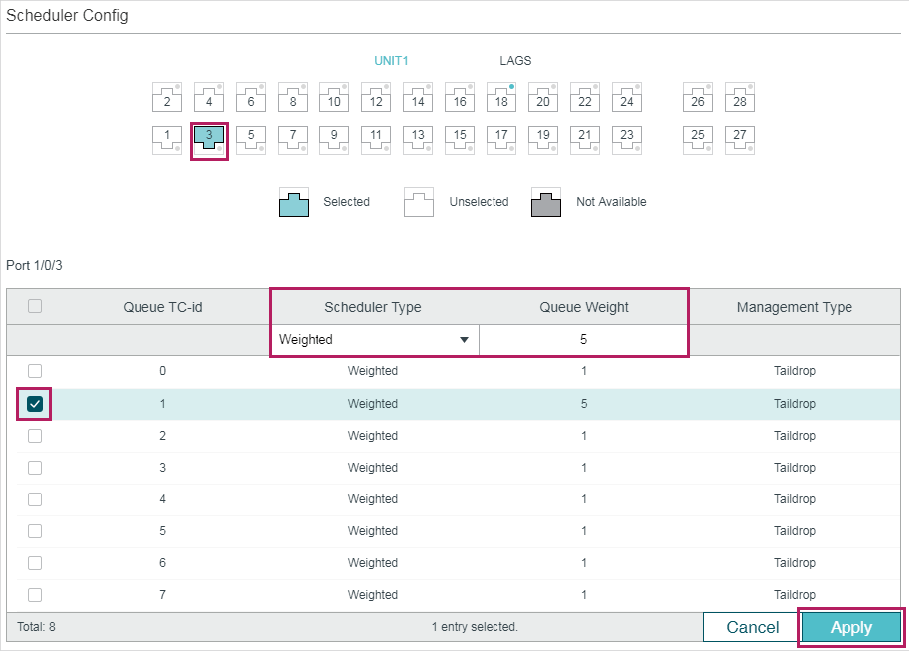
3)Choose the menu QoS > Class of Service > Scheduler Settings to load the following page. Select the port 1/0/3 and set the scheduler type of TC-0 and TC-1 as Weighted. Specify the queue weight of TC-0 as 1 and specify the queue weight of TC-1 as 5. Click Apply.
Figure 6-4 Configuring the Egress Queue
4)Click  to save the settings.
6.1.4Using the CLI
1)Set the trust mode of port 1/0/1 as untrusted and specify the 802.1p priority as 1.
Switch_A#configure
Switch_A(config)#interface gigabitEthernet 1/0/1
Switch_A(config-if)#qos trust mode untrust
Switch_A(config-if)#qos port-priority 1
Switch_A(config-if)#exit
2)Set the trust mode of port 1/0/2 as untrusted and specify the 802.1p priority as 0.
Switch_A(config)#interface gigabitEthernet 1/0/2
Switch_A(config-if)#qos trust mode untrust
Switch_A(config-if)#qos port-priority 0
Switch_A(config-if)#exit
3)Map the 802.1p priority 0 to TC-1 and map the 802.1p priority 1 to TC-0.
Switch_A(config)#qos cos-map 0 1
Switch_A(config)#qos cos-map 1 0
4)Set the scheduler type of TC-0 and TC-1 as Weighted for egress port 1/0/3. Specify the queue weight of TC-0 as 1 and specify the queue weight of TC-1 as 5.
Switch_A(config)#interface gigabitEthernet 1/0/3
Switch_A(config-if)#qos queue 0 mode wrr weight 1
Switch_A(config-if)#qos queue 1 mode wrr weight 5
Switch_A(config-if)#end
Switch_A#copy running-config startup-config
Verify the configurations
Verify the trust mode of the port:
Switch_A#show qos trust interface
Port Trust Mode LAG
-------- --------- --------
Gi1/0/1 untrust N/A
Gi1/0/2 untrust N/A
Gi1/0/3 untrust N/A
Gi1/0/4 untrust N/A
...
Verify the port to 802.1p mappings:
Switch_A#show qos port-priority interface
Port CoS Value LAG
-------- --------- --------
Gi1/0/1 CoS 1 N/A
Gi1/0/2 CoS 0 N/A
Gi1/0/3 CoS 0 N/A
Gi1/0/4 CoS 0 N/A
...
Verify the 802.1p to queue mappings:
Switch_A#show qos cos-map
---------------+-----+-----+-----+-----+-----+-----+----+----
Dot1p Value |0 |1 |2 |3 |4 |5 |6 |7
---------------+-----+-----+-----+-----+-----+-----+----+----
TC |TC1 |TC0 |TC2 |TC4 |TC4 |TC5 |TC6 |TC7
---------------+-----+-----+-----+-----+-----+-----+----+----
Verify the scheduler mode of the egress port:
Switch _A#show qos queue interface gigabitEthernet 1/0/3
Gi1/0/3----LAG: N/A
Queue Schedule Mode Weight
----- ---------- -----
TC0 WRR 1
TC1 WRR 5
TC2 WRR 1
TC3 WRR 1
TC4 WRR 1
TC5 WRR 1
TC6 WRR 1
TC7 WRR 1
6.2.1Network Requirements
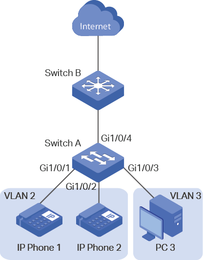
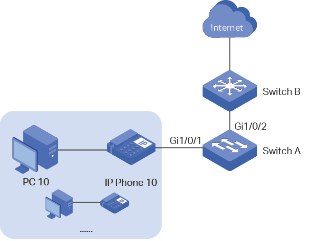
As shown below, the company plans to install IP phones in the office area. To ensure the good voice quality, IP phones and the computers will be connected to the different ports of the switch, and the voice traffic requires a higher priority than the data traffic.
Figure 6-5 Voice VLAN Application Topology
6.2.2Configuration Scheme
To implement this requirement, you can configure Voice VLAN to ensure that the voice traffic can be transmitted in the same VLAN and the data traffic is transmitted in another VLAN. In addition, specify the priority to make the voice traffic can take precedence when the congestion occurs.
1)Configure 802.1Q VLAN for port 1/0/1, port 1/0/2. port 1/0/3 and port 1/0/4.
2)Configure Voice VLAN feature on port 1/0/1 and port 1/0/2.
Demonstrated with T2600G-28TS, the following sections provide configuration procedure in two ways: using the GUI and using the CLI.
6.2.3Using the GUI
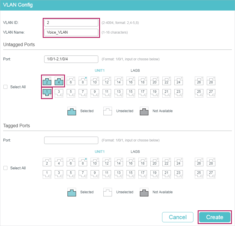
1)Choose the menu L2 FEATURES > VLAN > 802.1Q VLAN > VLAN Config and click to load the following page. Create VLAN 2 and add untagged port 1/0/1, port 1/0/2 and port 1/0/4 to VLAN 2. Click Create.
Figure 6-6 Configuring VLAN 2
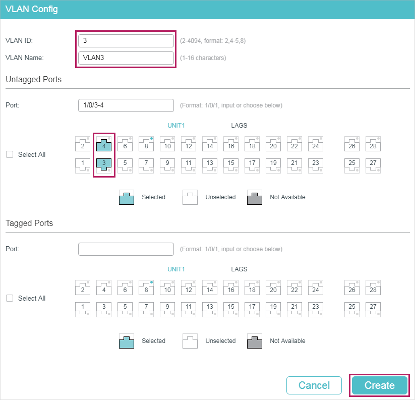
2)Click to load the following page. Create VLAN 3 and add untagged port 1/0/3 and port 1/0/4 to VLAN 3. Click Create.
Figure 6-7 Configuring VLAN 3
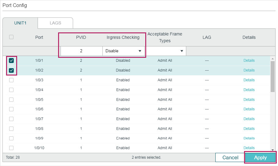
3)Choose the menu L2 FEATURES > VLAN > 802.1Q VLAN > Port Config to load the following page. Disable the Ingress Checking feature on port 1/0/1 and port 1/0/2 and specify the PVID as 2. Click Apply.
Figure 6-8 Specifying the Parameters of the Ports
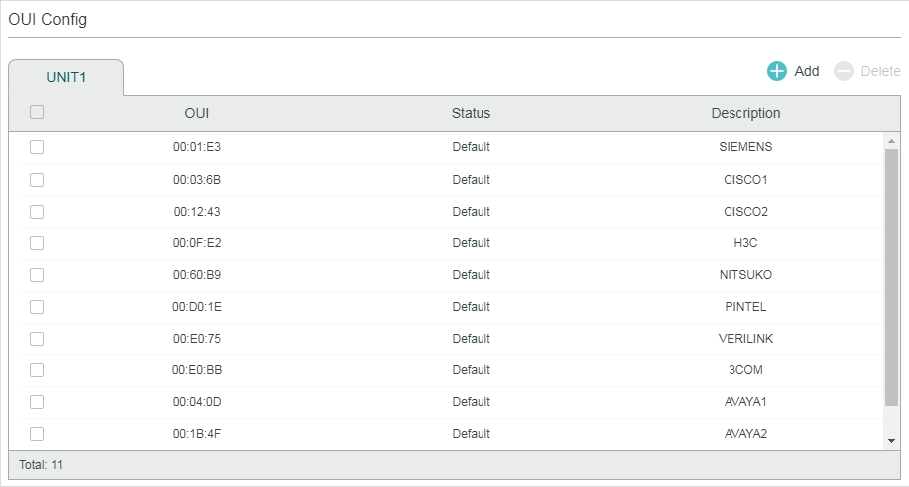
4)Choose the menu QoS > Voice VLAN > OUI Config to load the following page. Check the OUI table.
Figure 6-9 Checking the OUI Table
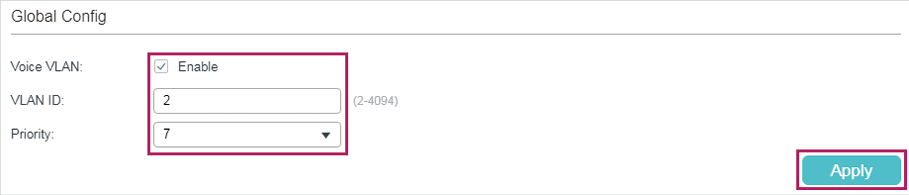
5)Choose the menu QoS > Voice VLAN > Global Config to load the following page. Enable Voice VLAN globally. Specify the VLAN ID as 2 and set the priority as 7. Click Apply.
Figure 6-10 Configuring Voice VLAN Globally
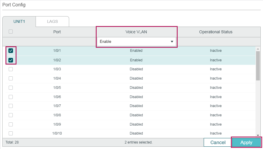
6)Choose the menu QoS > Voice VLAN > Port Config to load the following page. Enable Voice VLAN on port 1/0/1 and port 1/0/2. Click Apply.
Figure 6-11 Enabling Voice VLAN on Ports
7)Click to save the settings.
6.2.4Using the CLI
1)Create VLAN 2 and add untagged port 1/0/1, port 1/0/2 and port 1/0/4 to VLAN 2.
Switch_A#configure
Switch_A(config)#vlan 2
Switch_A(config-vlan)#name VoiceVLAN
Switch_A(config-vlan)#exit
Switch_A(config)#interface gigabitEthernet 1/0/1
Switch_A(config-if)#switchport general allowed vlan 2 untagged
Switch_A(config-if)#exit
Switch_A(config)#interface gigabitEthernet 1/0/2
Switch_A(config-if)#switchport general allowed vlan 2 untagged
Switch_A(config-if)#exit
Switch_A(config)#interface gigabitEthernet 1/0/4
Switch_A(config-if)#switchport general allowed vlan 2 untagged
Switch_A(config-if)#exit
2)Create VLAN 3 and add untagged port 1/0/3 and port 1/0/4 to VLAN 3.
Switch_A(config)#vlan 3
Switch_A(config-vlan)#name VLAN3
Switch_A(config-vlan)#exit
Switch_A(config)#interface gigabitEthernet 1/0/3
Switch_A(config-if)#switchport general allowed vlan 3 untagged
Switch_A(config-if)#exit
Switch_A(config)#interface gigabitEthernet 1/0/4
Switch_A(config-if)#switchport general allowed vlan 3 untagged
Switch_A(config-if)#exit
3)Disable the Ingress Checking feature on port 1/0/1 and port 1/0/2 and specify the PVID as 2.
Switch_A(config)#interface gigabitEthernet 1/0/1
Switch_A(config-if)#no switchport check ingress
Switch_A(config-if)#switchport pvid 2
Switch_A(config-if)#exit
Switch_A(config)#interface gigabitEthernet 1/0/2
Switch_A(config-if)#no switchport check ingress
Switch_A(config-if)#switchport pvid 2
Switch_A(config-if)#exit
4)Check the OUI table.
Switch(config)#show voice vlan oui
00:01:E3 Default SIEMENS
00:03:6B Default CISCO1
00:12:43 Default CISCO2
00:0F:E2 Default H3C
00:60:B9 Default NITSUKO
00:D0:1E Default PINTEL
00:E0:75 Default VERILINK
00:E0:BB Default 3COM
00:04:0D Default AVAYA1
00:1B:4F Default AVAYA2
00:04:13 Default SNOM
5)Enable Voice VLAN globally. Specify the VLAN ID as 2 and set the priority as 7.
Switch_A(config)#voice vlan 2
Switch_A(config)#voice vlan priority 7
6)Enable Voice VLAN on port 1/0/1 and port 1/0/2.
Switch_A(config)#interface gigabitEthernet 1/0/1
Switch_A(config-if)#voice vlan
Switch_A(config-if)#exit
Switch_A(config)#interface gigabitEthernet 1/0/2
Switch_A(config-if)#voice vlan
Switch_A(config-if)#end
Switch_A#copy running-config startup-config
Verify the configurations
Verify the basic VLAN configuration:
Switch_A(config)#show vlan brief
VLAN Name Status Ports
----- ----------------- --------- ----------------------------------------
1 System-VLAN active Gi1/0/1, Gi1/0/2, Gi1/0/3, Gi1/0/4,
Gi1/0/5, Gi1/0/6, Gi1/0/7, Gi1/0/8,
Gi1/0/9, Gi1/0/10, Gi1/0/11, Gi1/0/12,
Gi1/0/13, Gi1/0/14, Gi1/0/15, Gi1/0/16,
Gi1/0/17, Gi1/0/18, Gi1/0/19, Gi1/0/20,
Gi1/0/21, Gi1/0/22, Gi1/0/23, Gi1/0/24,
Gi1/0/25, Gi1/0/26, Gi1/0/27, Gi1/0/28
2 VoiceVLAN active Gi1/0/1, Gi1/0/2, Gi1/0/4
3 VLAN3 active Gi1/0/3, Gi1/0/4
Verify the Voice VLAN configuration:
Switch_A(config)#show voice vlan interface
Voice VLAN ID 2
Priority 7
Interface Voice VLAN Mode Operational Status LAG
--------- --------------- ------------------ ---
Gi1/0/1 enabled Up N/A
Gi1/0/2 enabled Up N/A
Gi1/0/3 disabled Down N/A
Gi1/0/4 disabled Down N/A
Gi1/0/5 disabled Down N/A
...
Gi1/0/28 disabled Down N/A
6.3.1Network Requirements
As shown below, the company plans to install IP phones in the office area. IP phones share switch ports used by computers, because no more ports are available for IP phones. To ensure the good voice quality, the voice traffic requires a higher priority than the data traffic.
Figure 6-12 Auto VoIP Application Topology
6.3.2Configuration Scheme
To optimize voice traffic, configure Auto VoIP and LLDP-MED to instruct IP Phones to send traffic with desired DSCP priority. Voice traffic is put in the desired queue and data traffic is put in other queues according to the Class of Service configurations. Make sure that the voice traffic can take precedence when congestion occurs.
1)Enable the Auto VoIP feature and configure the DSCP value of ports.
2)Configure Class of Service.
3)Enable LLDP-MED and configure the corresponding parameters.
Demonstrated with T2600G-28TS, the following sections provide configuration procedure in two ways: using the GUI and using the CLI.
6.3.3Using the GUI
Auto VoIP configurations for port1/0/1 and other ports connected to the IP phone are the same, the following configuration procedures take port 1/0/1 as example.
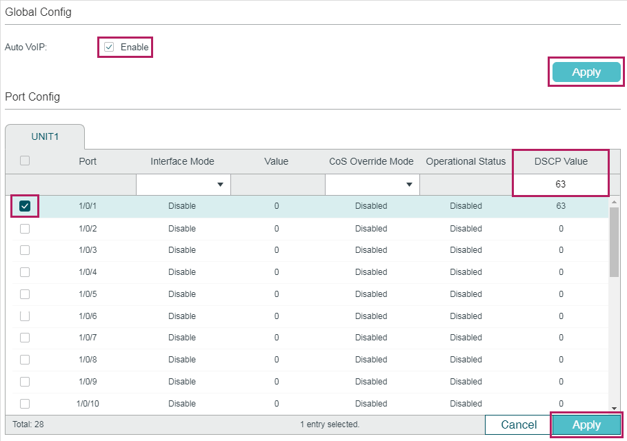
1)Choose the menu QoS > Auto VoIP to load the following page. Enable Auto VoIP globally and specify the DSCP value of port 1/0/1 as 63. Click Apply.
Figure 6-13 Configuring Auto VoIP
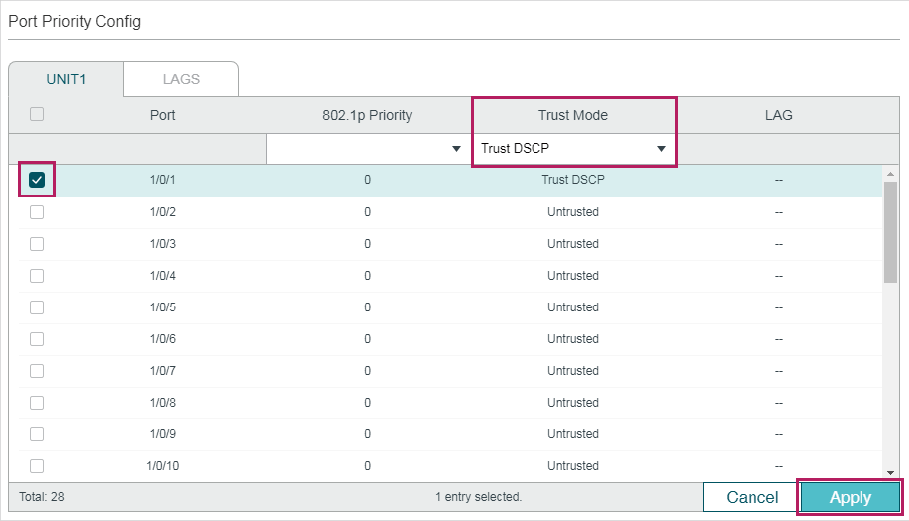
2)Choose the menu QoS > Class of Service > Port Priority to load the following page. Set the trust mode of port 1/0/1 as trust DSCP. Click Apply.
Figure 6-14 Configuring Port Priority
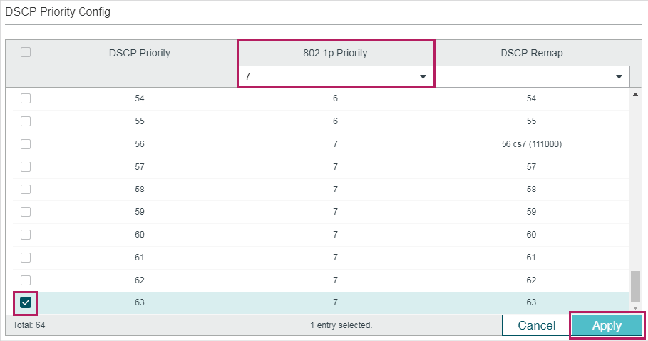
3)Choose the menu QoS > Class of Service > DSCP Priority to load the following page. Specify the 802.1p priority as 7 for DSCP priority 63. Click Apply.
Figure 6-15 Specifying the 802.1p priority for DSCP priority 63
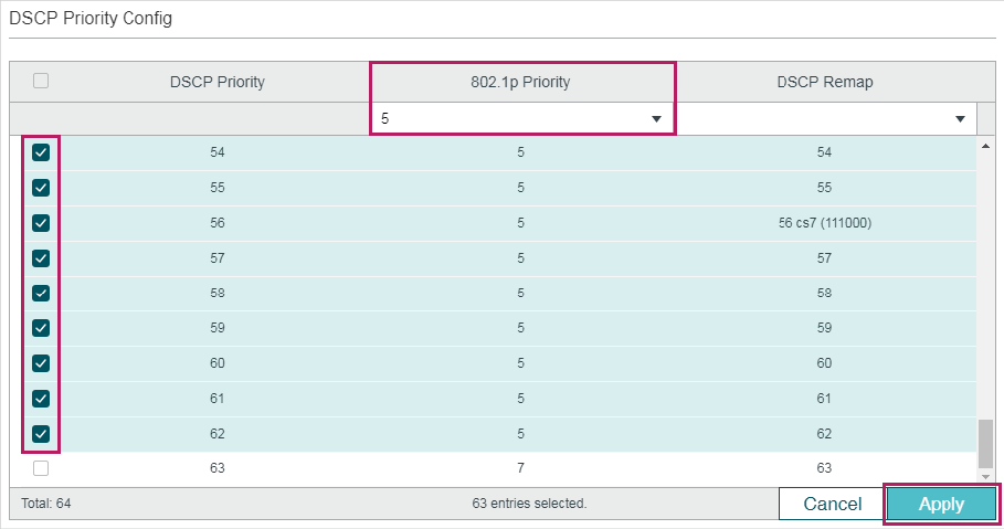
4)Specify the 802.1p priority as 5 for other DSCP priorities. Click Apply.
Figure 6-16 Specifying the 802.1p priority for Other DSCP priorities
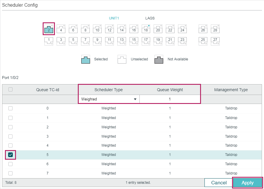
5)Choose the menu QoS > Class of Service > Scheduler Settings to load the following page. Select port 1/0/2. Set the scheduler mode as weighted and specify the queue weight as 1 for TC-5. Click Apply.
Figure 6-17 Configuring the TC-5 for the Port
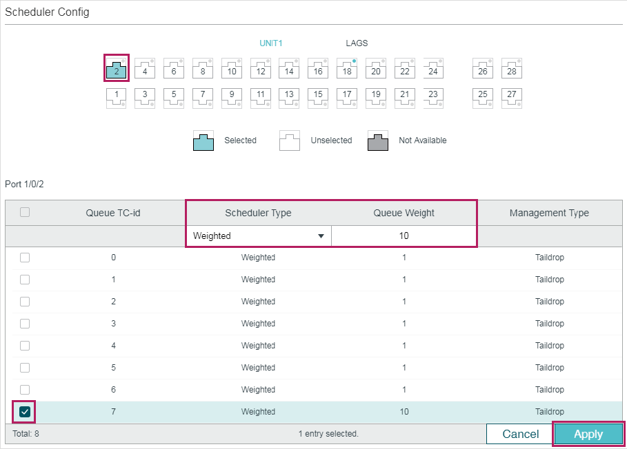
6)Select port 1/0/2. Set the scheduler mode as weighted and specify the queue weight as 10 for TC-7. Click Apply.
Figure 6-18 Configuring the TC-7 for the Port
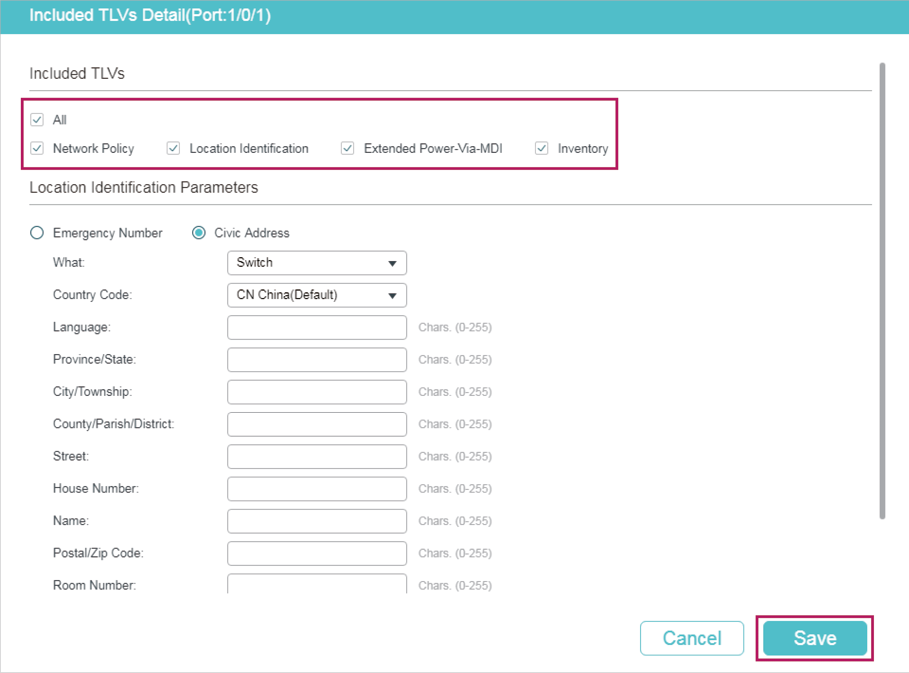
7)Choose the menu L2 FEATURES > LLDP > LLDP-MED Config > Port Config click Detail to of port1/0/1 to load the following page. Check the boxes of all the TLVs. Click Save.
Figure 6-19 Configuring the TLVs
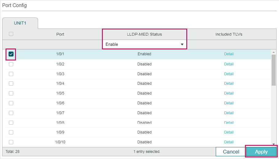
8)Choose the menu L2 FEATURES > LLDP > LLDP-MED Config > Port Config to load the following page. Enable LLDP-MED on port 1/0/1. Click Apply.
Figure 6-20 Enabling LLDP-MED on the Port
9)Click to save the settings.
6.3.4Using the CLI
1)Enable Auto VoIP globally and specify the DSCP value of port 1/0/1 as 63.
Switch_A#configure
Switch_A(config)#auto-voip
Switch_A(config)#interface gigabitEthernet 1/0/1
Switch_A(config-if)#auto-voip dscp 63
Switch_A(config-if)#exit
2)Set the trust mode of port 1/0/1 as trust DSCP. Specify the 802.1p priority as 7 for DSCP priority 63 and specify 802.1p priority as 5 for other DSCP priorities.
Switch_A(config)#interface gigabitEthernet 1/0/1
Switch_A(config-if)#qos trust mode dscp
Switch_A(config-if)#exit
Switch_A(config)#qos dscp-map 63 7
Switch_A(config)#qos dscp-map 0-62 5
3)On port 1/0/1, set the scheduler mode as weighted and specify the queue weight as 1 for TC-5. Set the scheduler mode as weighted and specify the queue weight as 10 for TC-7.
Switch_A(config)#interface gigabitEthernet 1/0/1
Switch_A(config-if)#qos queue 5 mode wrr weight 1
Switch_A(config-if)#qos queue 7 mode wrr weight 10
Switch_A(config-if)#exit
4)Enable LLDP-MED on port 1/0/1 and select all the TLVs to be included in outgoing LLDPDU.
Switch_A(config)#interface gigabitEthernet 1/0/1
Switch_A(config-if)#lldp med-status
Switch_A(config-if)#lldp med-tlv-select all
Switch_A(config-if)#end
Switch_A#copy running-config startup-config
Verify the configurations
Verify the configuration of Auto VoIP:
Switch_A(config)#show auto-voip
Administrative Mode: Enabled
Verify the Auto VoIP configuration of ports:
Switch_A(config)#show auto-voip interface
Interface.Gi1/0/1
Auto-VoIP Interface Mode. Disabled
Auto-VoIP COS Override. False
Auto-VoIP DSCP Value. 63
Auto-VoIP Port Status. Disabled
Interface.Gi1/0/2
Auto-VoIP Interface Mode. Disabled
Auto-VoIP COS Override. False
Auto-VoIP DSCP Value. 0
Auto-VoIP Port Status. Disabled
Interface.Gi1/0/3
Auto-VoIP Interface Mode. Disabled
Auto-VoIP COS Override. False
Auto-VoIP DSCP Value. 0
Auto-VoIP Port Status. Disabled
...
Verify the configuration of Class of Service:
Switch_A(config)#show qos trust interface gigabitEthernet 1/0/1
Port Trust Mode LAG
-------- --------- ------
Gi1/0/1 trust DSCP N/A
Switch_A(config)#show qos cos-map
---------------+-----+-----+-----+-----+-----+-----+----+----
Dot1p Value |0 |1 |2 |3 |4 |5 |6 |7
---------------+-----+-----+-----+-----+-----+-----+----+----
TC |TC1 |TC0 |TC2 |TC3 |TC4 |TC5 |TC6 |TC7
---------------+-----+-----+-----+-----+-----+-----+----+----
Switch_A(config)#show qos dscp-map
DSCP: 0 1 2 3 4 5 6 7
DSCP to 802.1P 5 5 5 5 5 5 5 5
---- ---- ---- ---- ---- ---- ---- ----
DSCP: 8 9 10 11 12 13 14 15
DSCP to 802.1P 5 5 5 5 5 5 5 5
---- ---- ---- ---- ---- ---- ---- ----
DSCP: 16 17 18 19 20 21 22 23
DSCP to 802.1P 5 5 5 5 5 5 5 5
---- ---- ---- ---- ---- ---- ---- ----
DSCP: 24 25 26 27 28 29 30 31
DSCP to 802.1P 5 5 5 5 5 5 5 5
---- ---- ---- ---- ---- ---- ---- ----
DSCP: 32 33 34 35 36 37 38 39
DSCP to 802.1P 5 5 5 5 5 5 5 5
---- ---- ---- ---- ---- ---- ---- ----
DSCP: 40 41 42 43 44 45 46 47
DSCP to 802.1P 5 5 5 5 5 5 5 5
---- ---- ---- ---- ---- ---- ---- ---
DSCP: 48 49 50 51 52 53 54 55
DSCP to 802.1P 5 5 5 5 5 5 5 5
---- ---- ---- ---- ---- ---- ---- ----
DSCP: 56 57 58 59 60 61 62 63
DSCP to 802.1P 5 5 5 5 5 5 5 7
---- ---- ---- ---- ---- ---- ---- ---
Verify the configuration of LLDP-MED:
Switch_A(config)#show lldp interface
LLDP interface config:
gigabitEthernet 1/0/1:
Admin Status: TxRx
SNMP Trap: Disabled
TLV Status
--- ------
Port-Description Yes
System-Capability Yes
System-Description Yes
System-Name Yes
Management-Address Yes
Port-VLAN-ID Yes
Protocol-VLAN-ID Yes
VLAN-Name Yes
Link-Aggregation Yes
MAC-Physic Yes
Max-Frame-Size Yes
Power Yes
LLDP-MED Status: Enabled
TLV Status
--- ------
Network Policy Yes
Location Identification Yes
Extended Power Via MDI Yes
Inventory Management Yes
...
Default settings of Class of Service are listed in the following tables.
Table 7-1Default Settings of Port Priority Configuration
|
Parameter |
Default Setting |
|
802.1P Priority |
0 |
|
Trust Mode |
Untrusted |
Table 7-2Default Settings of 802.1p to Queue Mapping
|
802.1p Priority |
Queues (8) |
|
0 |
TC1 |
|
1 |
TC0 |
|
2 |
TC2 |
|
3 |
TC3 |
|
4 |
TC4 |
|
5 |
TC5 |
|
6 |
TC6 |
|
7 |
TC7 |
Table 7-3Default Settings of 802.1p Remap Configuration
|
Original 802.1p Priority |
New 802.1p Priority |
|
0 |
0 |
|
1 |
1 |
|
2 |
2 |
|
3 |
3 |
|
4 |
4 |
|
5 |
5 |
|
6 |
6 |
|
7 |
7 |
Table 7-4Default Settings of DSCP to 802.1p Mapping
|
DSCP |
802.1p Priority |
|
0 to 7 |
0 |
|
8 to 15 |
1 |
|
16 to 23 |
2 |
|
24 to 31 |
3 |
|
32 to 39 |
4 |
|
40 to 47 |
5 |
|
48 to 55 |
6 |
|
56 to 63 |
7 |
Table 7-5Default Settings of DSCP Remap Configuration
|
Original DSCP |
New DSCP |
Original DSCP |
New DSCP |
Original DSCP |
New DSCP |
|
0 |
0 be (000000) |
22 |
22 af23 (010110) |
44 |
44 |
|
1 |
1 |
23 |
23 |
45 |
45 |
|
2 |
2 |
24 |
24 cs3 (011000) |
46 |
46 ef (101110) |
|
3 |
3 |
25 |
25 |
47 |
47 |
|
4 |
4 |
26 |
26 af31 (011010) |
48 |
48 cs6 (110000) |
|
5 |
5 |
27 |
27 |
49 |
49 |
|
6 |
6 |
28 |
28 af32 (011100) |
50 |
50 |
|
7 |
7 |
29 |
29 |
51 |
51 |
|
8 |
8 cs1 (001000) |
30 |
30 af33 (011110) |
52 |
52 |
|
9 |
9 |
31 |
31 |
53 |
53 |
|
10 |
10 af11 (001010) |
32 |
32 cs4 (100000) |
54 |
54 |
|
11 |
11 |
33 |
33 |
55 |
55 |
|
12 |
12 af12 (001100) |
34 |
34 af41 (100010) |
56 |
56 cs7 (111000) |
|
13 |
13 |
35 |
35 |
57 |
57 |
|
14 |
14 af13 (001110) |
36 |
36 af42 (100100) |
58 |
58 |
|
15 |
15 |
37 |
37 |
59 |
59 |
|
16 |
16 cs2 (010000) |
38 |
38 af43 (100110) |
60 |
60 |
|
17 |
17 |
39 |
39 |
61 |
61 |
|
18 |
18 af21 (010010) |
40 |
40 cs5 (101000) |
62 |
62 |
|
19 |
19 |
41 |
41 |
63 |
63 |
|
20 |
20 af22 (010100) |
42 |
42 |
||
|
21 |
21 |
43 |
43 |
Table 7-6Default Settings of Scheduler Settings Configuration
|
Parameter |
Default Setting |
|
Scheduler Type |
Weighted |
|
Queue Weight |
1 |
|
Management Type |
Taildrop |
Default settings of Class of Service are listed in the following tables.
Table 7-7Default Settings of Bandwidth Control
|
Parameter |
Default Setting |
|
Ingress Rate (0-1,000,000Kbps) |
0 |
|
Egress Rate (0-1,000,000Kbps) |
0 |
Table 7-8Default Settings of Storm Control
|
Parameter |
Default Setting |
|
Rate Mode |
kbps |
|
Broadcast Threshold (0-1,000,000) |
0 |
|
Multicast Threshold (0-1,000,000) |
0 |
|
UL-Frame Threshold (0-1,000,000) |
0 |
|
Action |
Drop |
|
Recover Time |
0 |
Default settings of Voice VLAN are listed in the following tables.
Table 7-9Default Settings of Global Configuration
|
Parameter |
Default Setting |
|
Voice VLAN |
Disabled |
|
VLAN ID |
None |
|
Priority |
7 |
Table 7-10Default Settings of Port Configuration
|
Parameter |
Default Setting |
|
Voice VLAN |
Disabled |
Table 7-11Default Settings of OUI Table
|
OUI |
Status |
Description |
|
00:01:E3 |
Default |
SIEMENS |
|
00:03:6B |
Default |
CISCO1 |
|
00:12:43 |
Default |
CISCO2 |
|
00:0F:E2 |
Default |
H3C |
|
00:60:B9 |
Default |
NITSUKO |
|
00:D0:1E |
Default |
PINTEL |
|
00:E0:75 |
Default |
VERILINK |
|
00:E0:BB |
Default |
3COM |
|
00:04:0D |
Default |
AVAYA1 |
|
00:1B:4F |
Default |
AVAYA2 |
|
00:04:13 |
Default |
SNOM |
Default settings of Auto VoIP are listed in the following tables.
Table 7-12Default Settings of Auto VoIP
|
Parameter |
Default Setting |
|
Interface Mode |
Disabled |
|
Value |
None |
|
Cos Override Mode |
Disabled |
|
DSCP Value |
0 |