Configuring LLDP
CHAPTERS
7. Appendix: Default Parameters
|
|
This guide applies to: T1500G-8T v2 or above, T1500G-10PS v2 or above, T1500G-10MPS v2 or above, T1500-28PCT v3 or above, T1600G-18TS v2 or above, T1600G-28TS v3 or above, T1600G-28PS v3 or above, T1600G-52TS v3 or above, T1600G-52PS v3 or above, T1700X-16TS v3 or above, T1700G-28TQ v3 or above, T2500G-10TS v2 or above, T2600G-18TS v2 or above, T2600G-28TS v3 or above, T2600G-28MPS v3 or above, T2600G-28SQ v1 or above, T2600G-52TS v3 or above. |

1.1Overview
LLDP (Link Layer Discovery Protocol) is a neighbor discovery protocol that is used for network devices to advertise information about themselves to other devices on the network. This protocol is a standard IEEE 802.1ab defined protocol and runs over the Layer 2 (the data-link layer) , which allows for interoperability between network devices of different vendors.
With LLDP enabled, the switch can get its neighbors’ information, and network administrators can use the NMS (Network Management System) to gather these information, helping them to know about the network topology, examine the network connectivity and troubleshoot the network faults.
LLDP-MED (LLDP for Media Endpoint Discovery) is an extension of LLDP and is used to advertise information between network devices and media endpoints. It is specially used together with Auto VoIP (Voice over Internet Protocol) to allow VoIP device to access the network. VoIP devices can use LLDP-MED for auto-configuration to minimize the configuration effort.
1.2Supported Features
The switch supports LLDP and LLDP-MED.
LLDP allows the local device to encapsulate its management address, device ID, interface ID and other information into a LLDPDU (Link Layer Discovery Protocol Data Unit) and periodically advertise this LLDPDU to its neighbor devices. The neighbors store the received LLDPDU in a standard MIB (Management Information Base), making it possible for the information to be accessed by a NMS (Network Management System) using a management protocol such as the SNMP (Simple Network Management Protocol).
LLDP-MED allows the network device to send its information including Auto VoIP information, PoE (Power over Ethernet) capacity and more to the media endpoint devices (for example, IP phones) for auto-configuration. The media endpoint devices receive the Auto VoIP information and finish the auto-configuration, then send the voice traffic with the desired configuration, which can provide preferential treatment to the voice traffic.
T configure LLDP function, follow the steps:
1)Configure the LLDP feature globally.
2)Configure the LLDP feature for the port.
2.1.1Configuring LLDP Globally
Choose the L2 FEATURES > LLDP > LLDP Config > Global Config to load the following page.
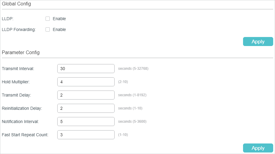
Figure 2-1 Global Config
Follow these steps to configure the LLDP feature globally.
1)In the Global Config section, enable LLDP. You can also enable the switch to forward LLDP messages when LLDP function is disabled. Click Apply.
|
LLDP |
Enable LLDP function globally. |
|
LLDP Forwarding |
(Optional) Enable the switch to forward LLDP messages when LLDP function is disabled. |
2)In the Parameter Config section, configure the LLDP parameters. Click Apply.
|
Transmit Interval |
Enter the interval between successive LLDP packets that are periodically sent from the local device to its neighbors. The default is 30 seconds. |
|
Hold Multiplier |
This parameter is a multiplier on the Transmit Interval that determines the actual TTL (Time To Live) value used in an LLDP packet. TTL is the duration that the neighbor device should hold the received LLDP packet before discarding it. The default value is 4. TTL= Hold Multiplier * Transmit Interval. |
|
Transmit Delay |
Specify the amount of time that the local device waits before sending another LLDP packet to its neighbor. When the local information changes, the local device will send LLDP packets to inform its neighbors. If frequent changes occur to the local device, LLDP packets will flood. After specifying a transmit delay time, the local device will wait for a delay time to send LLDP packets when changes occur to avoid frequent LLDP packet forwarding. The default is 2 seconds. |
|
Reinitialization Delay |
Specify the amount of delay from when Admin Status of ports becomes “Disable’ until reinitialization will be attempted. The default value is 2 seconds. |
|
Notification Interval |
Enter the interval between successive in seconds Trap messages that are periodically sent from the local device to the NMS. The default value is 5. |
|
Fast Start Repeat Count |
Specify the number of LLDP packets that the local port sends when its Admin Status changes from Disable (or Rx_Only) to Tx&RX (or Tx_Only). The default value is 3. In this case, the local device will shorten the Transmit Interval of LLDP packets to 1 second to make it quickly discovered by its neighbors. After the specified number of LLDP packets are sent, the Transmit Interval will be restored to the specified value. |
2.1.2Configuring LLDP For the Port
Choose th menu L2 FEATURES > LLDP > LLDP Config > Port Config to load the following page.
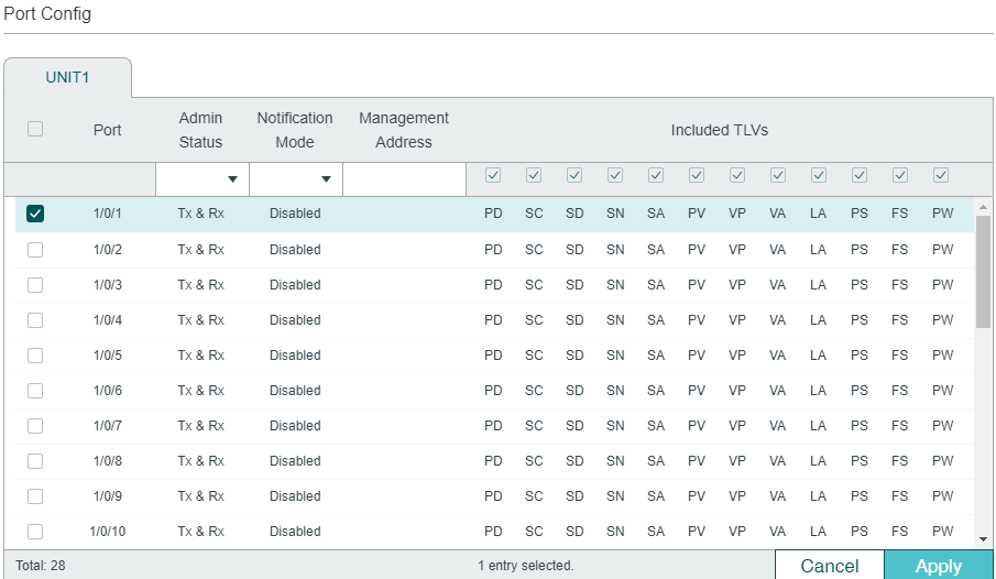
Figure 2-2 Port Config
Follow these steps to configure the LLDP feature for the interface.
1)Select one or more ports to configure.
2)Configure the Admin Status and Notification Mode for the port.
|
Admin Status |
Set Admin Status for the port to deal with LLDP packets. Tx&Rx: The port transmits LLDP packets and receives LLDP packets. Rx_Only: The port only receives LLDP packets. Tx_Only: The port only transmits LLDP packets. Disable: The port will not transmit LLDP packets or drop the received LLDP packets. |
|
Notification Mode |
(Optional) Enable the switch to send trap messages to the NMS when the information of the neighbor device connected to this port changes. |
|
Management Address |
Specify the Management IP address of the port to be notified to the neighbor. Value 0.0.0.0 means the port will notify its default management address to the neighbor. |
3)Select the TLVs (Type/Length/Value) included in the LLDP packets according to your needs.
|
Included TLVs |
Configure the TLVs included in the outgoing LLDP packets. The switch supports the following TLVs: PD: Used to advertise the port description defined by the IEEE 802 LAN station. SC: Used to advertise the supported functions and whether or not these functions are enabled. SD: Used to advertise the system’s description including the full name and version identification of the system’s hardware type, software operating system, and networking software. SN: Used to advertise the system name. SA: Used to advertise the local device’s management address to make it possible to be managed by SNMP. PV: Used to advertise the 802.1Q VLAN ID of the port. VP: Used to advertise the protocol VLAN ID of the port. VA: Used to advertise the name of the VLAN which the port is in. LA: Used to advertise whether the link is capable of being aggregated, whether the link is currently in an aggregation, and the port ID when it is in an aggregation. PS: Used to advertise the port’s attributes including the duplex and bit-rate capability of the sending IEEE 802.3 LAN node that is connected to the physical medium, the current duplex and bit-rate settings of the sending IEEE 802.3 LAN node and whether these settings are the result of auto-negotiation during link initiation or of manual set override action. FS: Used to advertise the maximum frame size capability of the implemented MAC and PHY. PW: Used to advertise the port’s PoE (Power over Ethernet) support capabilities. |
4)Click Apply.
2.2Using the CLI
2.2.1Global Config
Enable the LLDP feature on the switch and configure the LLDP parameters.
|
Step 1 |
configure Enter global configuration mode. |
|
Step 2 |
lldp Enable the LLDP feature on the switch. |
|
Step 3 |
lldp forward_message (Optional) Enable the switch to forward LLDP messages when LLDP function is disabled. |
|
Step 4 |
lldp hold-multiplier multiplier (Optional) Specify the amount of time the neighbor device should hold the received information before discarding it. This parameter is a multiplier on the Transmit Interval that determines the actual TTL (Time To Live) value used in an LLDP packet. TTL is the duration that the neighbor device should hold the received LLDP packet before discarding it. TTL= Hold Multiplier * Transmit Interval. multiplier: Specify the hold-multiplier. The valid value ranges from 2 to 10, and the default value is 4. |
|
Step 5 |
lldp timer { tx-interval tx-interval | tx-delay tx-delay | reinit-delay reinit-delay | notify-interval notify-interval | fast-count fast-count } (Optional) Configure the timers for LLDP packet forwarding. tx-interval: Enter the interval between successive LLDP packets that are periodically sent from the local device to its neighbors. tx-delay: Specify the amount of time that the local device waits before sending another LLDP packet to its neighbors. The default is 2 seconds. reinit-delay: Specify the amount of time that the local device waits before sending another LLDP packet to its neighbors. The default is 2 seconds. notify-interval: Enter the interval between successive Trap messages that are periodically sent from the local device to the NMS. The default is 5 seconds. fast-count: Specify the number of packets that the local port sends when its Admin Status changes. The default is 3. |
|
Step 6 |
show lldp Display the LLDP information. |
|
Step 7 |
end Return to Privileged EXEC Mode. |
|
Step 8 |
copy running-config startup-config Save the settings in the configuration file. |
The following example shows how to configure the following parameters, lldp timer=4, tx-interval=30 seconds, tx-delay=2 seconds, reinit-delay=3 seconds, notify-iInterval=5 seconds, fast-count=3.
Switch#configure
Switch(config)#lldp
Switch(config)#lldp hold-multiplier 4
Switch(config)#lldp timer tx-interval 30 tx-delay 2 reinit-delay 3 notify-interval 5 fast-count 3
Switch(config)#show lldp
LLDP Status: Enabled
LLDP Forward Message: Disabled
Tx Interval: 30 seconds
TTL Multiplier: 4
Tx Delay: 2 seconds
Initialization Delay: 2 seconds
Trap Notification Interval: 5 seconds
Fast-packet Count: 3
LLDP-MED Fast Start Repeat Count: 4
Switch(config)#end
Switch#copy running-config startup-config
2.2.2Port Config
Select the desired port and set its Admin Status, Notification Mode and the TLVs included in the LLDP packets.
|
Step 1 |
configure Enter global configuration mode. |
|
Step 2 |
interface {fastEthernet port | range fastEthernet port-list | gigabitEthernet port | range gigabitEthernet port-list | ten-gigabitEthernet port | range ten-gigabitEthernet port-list ] Enter interface configuration mode. |
|
Step 3 |
lldp receive (Optional) Set the mode for the port to receive LLDP packets. It is enabled by default. |
|
Step 4 |
lldp transmit (Optional) Set the mode for the port to send LLDP packets. It is enabled by default. |
|
Step 5 |
lldp snmp-trap (Optional) Enable the Notification Mode feature on the port. If it is enabled, the local device will send trap messages to the NMS when neighbor information changed. It is disabled by default. |
|
Step 6 |
lldp tlv-select (Optional) Configure the TLVs included in the outgoing LLDP packets. By default, the outgoing LLDP packets include all TLVs. |
|
Step 7 |
show lldp interface { fastEthernet port | gigabitEthernet port | ten-gigabitEthernet port } Display LLDP configuration of the corresponding port. |
|
Step 8 |
end Return to Privileged EXEC Mode. |
|
Step 9 |
copy running-config startup-config Save the settings in the configuration file. |
The following example shows how to configure the port 1/0/1. The port can receive and transmit LLDP packets, its notification mode is enabled and the outgoing LLDP packets include all TLVs.
Switch#configure
Switch(config)#lldp
Switch(config)#interface gigabitEthernet 1/0/1
Switch(config-if)#lldp receive
Switch(config-if)#lldp transmit
Switch(config-if)#lldp snmp-trap
Switch(config-if)#lldp tlv-select all
Switch(config-if)#show lldp interface gigabitEthernet 1/0/1
LLDP interface config:
gigabitEthernet 1/0/1:
Admin Status: TxRx
SNMP Trap: Enabled
TLV Status
--- ------
Port-Description Yes
System-Capability Yes
System-Description Yes
System-Name Yes
Management-Address Yes
Port-VLAN-ID Yes
Protocol-VLAN-ID Yes
VLAN-Name Yes
Link-Aggregation Yes
MAC-Physic Yes
Max-Frame-Size Yes
Power Yes
Switch(config-if)#end
Switch#copy running-config startup-config
To configure LLDP-MED function, follow the steps:
1)Enable LLDP feature globally and configure the LLDP parametres for the ports.
2)Configuring LLDP-MED fast repeat count globally.
3)Enable and configure the LLDP-MED feature on the port.
Configuration Guidelines
LLDP-MED is used together with Auto VoIP to implement VoIP access. Besides the configuration of LLDP-MED feature, you also need configure the Auto VoIP feature. Refer to Configuring QoS_T1500&T1500G&T1600G or Configuring QoS_T2600G&T1600G-52TS v3&T1600G_52PS v3 for detailed instructions.
3.1Using the GUI
3.1.1Configuring LLDP Globally
Enable LLDP globally and configure the LLDP parametres for the ports. For the details of LLDP configuration, refer to LLDP Configurations.
3.1.1Configuring LLDP-MED Globally
Choose the menu L2 FEATURES > LLDP > LLDP-MED Config > Global Config to load the following page.
Figure 3-1 LLDP-MED Parameters Config
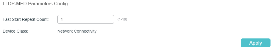
Configure the Fast Start Count and view the current device class. Click Apply.
|
Fast Start Repeat Count |
Specify the number of successive LLDP-MED packets that the switch sends when it receives the LLDP-MED packets from the neighbor endpoints. The default is 4. If the switch receives LLDP-MED packets from the neighbor endpoints for the first time, it will send the specified number of LLDP-MED packets carrying LLDP-MED information. After that, the transmit interval will be restored to the specified value. |
|
Device Class |
Display the current device class. LLDP-MED defines two device classes, Network Connectivity Device and Endpoint Device. The switch is a Network Connectivity device. |
3.1.2Configuring LLDP-MED for Ports
Choose the menu L2 FEATURES > LLDP > LLDP-MED Config > Port Config to load the following page.
Figure 3-2 LLDP-MED Port Config
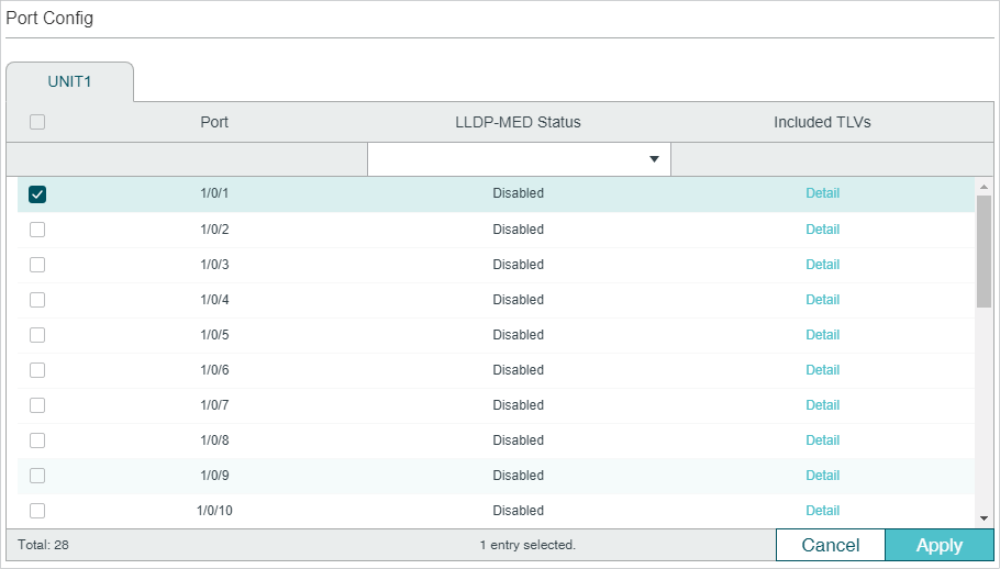
Follow these steps to enable LLDP-MED:
1)Select the desired port and enable LLDP-MED. Click Apply.
2)Click Detail to enter the following page. Configure the TLVs included in the outgoing LLDP packets. If Location Identification is selected, you need configure the Emergency Number or select Civic Address to configure the details. Click Apply.
Figure 3-3 LLDP-MED Port Config-Detail
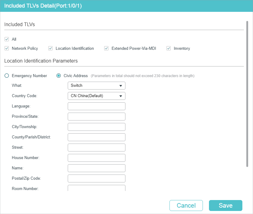
|
Network Policy |
Used to advertise VLAN configuration and the associated Layer 2 and Layer 3 attributes of the port to the endpoint devices. |
|
Location Identification |
Used to assign the location identifier information to the Endpoint devices. If this option is selected, you can configure the emergency number and the detailed address of the endpoint device in the Location Identification Parameters section. |
|
Extended Power-Via-MDI |
Used to advertise the detailed PoE information including power supply priority and supply status between LLDP-MED Endpoint devices and Network Connectivity devices. |
|
Inventory |
Used to advertise the inventory information. The Inventory TLV set contains seven basic Inventory management TLVs, that is, Hardware Revision TLV, Firmware Revision TLV, Software Revision TLV, Serial Number TLV, Manufacturer Name TLV, Model Name TLV and Asset ID TLV. |
|
Emergency Number |
Configure the emergency number to call CAMA or PSAP. The number should contain 10-25 characters. |
|
Civic Address |
Configure the address of the audio device in the IETF defined address format. What: Specify the role type of the local device, DHCP Server, Switch or LLDP-MED Endpoint. Country Code: Enter the country code defined by ISO 3166 , for example, CN, US. Language, Province/State etc.: Enter the regular details. |
3.2Using the CLI
3.2.1Global Config
|
Step 1 |
configure Enter global configuration mode. |
|
Step 2 |
lldp Enable the LLDP feature on the switch. |
|
Step 3 |
lldp med-fast-count count (Optional) Specify the number of successive LLDP-MED frames that the local device sends when fast start mechanism is activated. When the fast start mechanism is activated, the local device will send the specified number of LLDP packets carrying LLDP-MED information. count: The valid value are from 1 to 10. The default is 4. |
|
Step 4 |
show lldp Display the LLDP information. |
|
Step 5 |
end Return to Privileged EXEC Mode. |
|
Step 6 |
copy running-config startup-config Save the settings in the configuration file. |
The following example shows how to configure LLDP-MED fast count as 4:
Switch#configure
Switch(config)#lldp
Switch(config)#lldp med-fast-count 4
Switch(config)#show lldp
LLDP Status: Enabled
Tx Interval: 30 seconds
TTL Multiplier: 4
Tx Delay: 2 seconds
Initialization Delay: 2 seconds
Trap Notification Interval: 5 seconds
Fast-packet Count: 3
LLDP-MED Fast Start Repeat Count: 4
Switch(config)#end
Switch#copy running-config startup-config
3.2.2Port Config
Select the desired port, enable LLDP-MED and select the TLVs (Type/Length/Value) included in the outgoing LLDP packets according to your needs.
|
Step 1 |
configure Enter global configuration mode. |
|
Step 2 |
interface {fastEthernet port | range fastEthernet port-list | gigabitEthernet port | range gigabitEthernet port-list | ten-gigabitEthernet port | range ten-gigabitEthernet port-list ] Enter interface configuration mode. |
|
Step 3 |
lldp med-status (Optional) Enable the LLDP-MED on the port. It is disabled by default. |
|
Step 4 |
lldp med-tlv-select { [ inventory-management] [location] [network-policy] [power-management] [all ] } (Optional) Configure the LLDP-MED TLVs included in the outgoing LLDP packets. By default, the outgoing LLDP packets include all TLVs. If LLDP-MED Location TLV is selected, configure the parameters as follows: lldp med-location {emergency-number identifier | civic-address [language language | province-state province-state | lci-county-name county | lci-city city | street street | house-number house-number | name name | postal-zipcode postal-zipcode | room-number room-number | post-office-box post-office-box | additional additional | country-code country-code | what { dhcp-server | endpoint | switch } ] } Configure the LLDP-MED Location TLV included in the outgoing LLDP packets. Used to assign the location identifier information to the Endpoint devices. identifier: Configure the emergency number to call CAMA or PSAP. The number should contain 10-25 characters. language,province-state,county.etc: Configure the address in the IETF defined address format. |
|
Step 5 |
show lldp interface { fastEthernet port | gigabitEthernet port | ten-gigabitEthernet port } Display LLDP configuration of the corresponding port. |
|
Step 6 |
end Return to Privileged EXEC Mode. |
|
Step 7 |
copy running-config startup-config Save the settings in the configuration file. |
The following example shows how to enable LLDP-MED on port 1/0/1, configure the LLDP-MED TLVs included in the outgoing LLDP packets.
Switch(config)#lldp
Switch(config)#lldp med-fast-count 4
Switch(config)#interface gigabitEthernet 1/0/1
Switch(config-if)#lldp med-status
Switch(config-if)#lldp med-tlv-select all
Switch(config-if)#show lldp interface gigabitEthernet 1/0/1
LLDP interface config:
gigabitEthernet 1/0/1:
Admin Status: TxRx
SNMP Trap: Enabled
TLV Status
--- ------
Port-Description Yes
System-Capability Yes
System-Description Yes
System-Name Yes
Management-Address Yes
Port-VLAN-ID Yes
Protocol-VLAN-ID Yes
VLAN-Name Yes
Link-Aggregation Yes
MAC-Physic Yes
Max-Frame-Size Yes
Power Yes
LLDP-MED Status: Enabled
TLV Status
--- ------
Network Policy Yes
Location Identification Yes
Extended Power Via MDI Yes
Inventory Management Yes
Switch(config)#end
Switch#copy running-config startup-config
This chapter introduces how to view the LLDP settings on the local device.
4.1Using GUI
4.1.1Viewing LLDP Device Info
Viewing the Local Info
Choose the menu L2 FEATURES > LLDP > LLDP Config > Local Info to load the following page.
Figure 4-1 Local Info
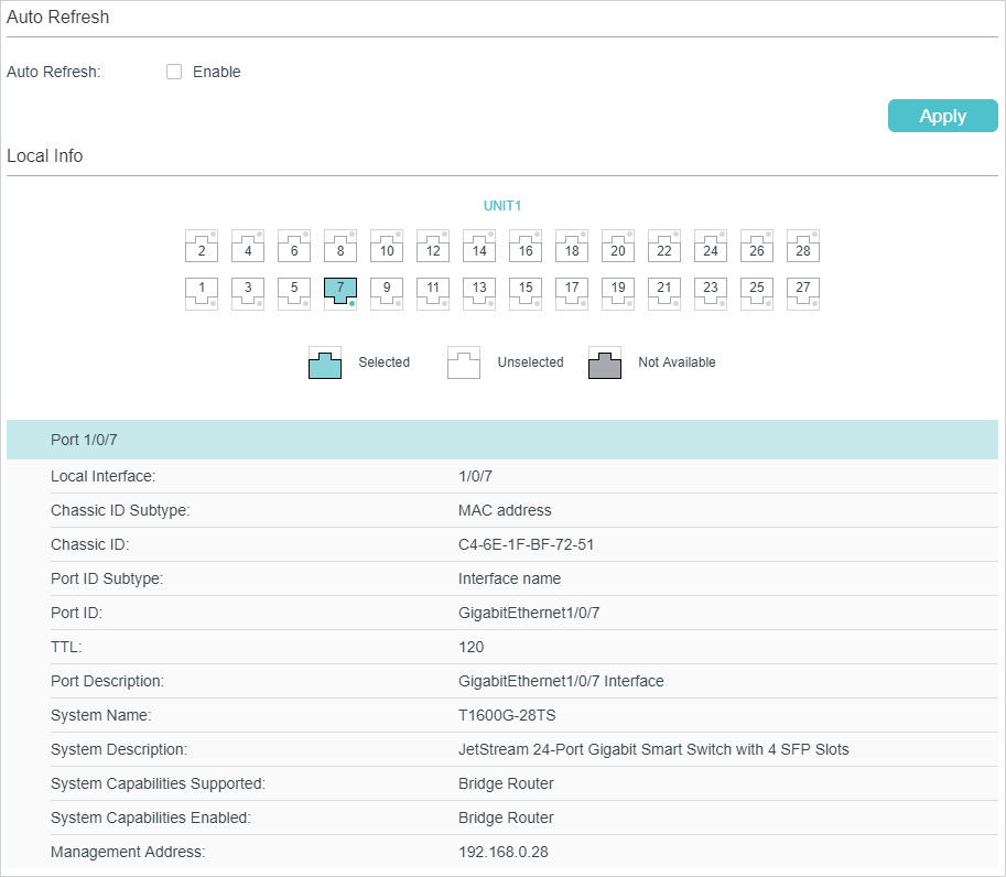
Follow these steps to view the local information:
1)In the Auto Refresh section, enable the Auto Refresh feature and set the Refresh Rate according to your needs. Click Apply.
2)In the Local Info section, select the desired port and view its associated local device information.
|
Local Interface |
Displays the local port ID. |
|
Chassis ID Subtype |
Displays the Chassis ID type. |
|
Chassis ID |
Displays the value of the Chassis ID. |
|
Port ID Subtype |
Displays the Port ID type. |
|
Port ID |
Displays the value of the Port ID. |
|
TTL |
Specify the amount of time in seconds the neighbor device should hold the received information before discarding it. |
|
Port Description |
Displays the description of the local port. |
|
System Name |
Displays the system name of the local device. |
|
System Description |
Displays the system description of the local device. |
|
System Capabilities Supported |
Displays the supported capabilities of the local system. |
|
System Capabilities Enabled |
Displays the primary functions of the local device. |
|
Management Address |
Displays the management IP address of the local device. |
Viewing the Neighbor Info
Choose the menu L2 FEATURES > LLDP > LLDP Config > Neighbor Info to load the following page.
Figure 4-2 Neighbor Info
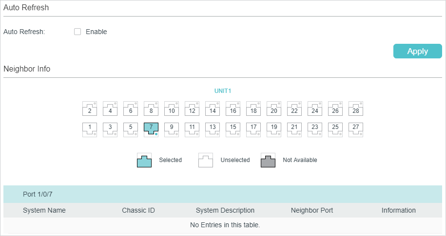
Follow these steps to view the neighbor information:
1)In the Auto Refresh section, enable the Auto Refresh feature and set the Refresh Rate according to your needs. Click Apply.
2)In the Neighbor Info section, select the desired port and view its associated neighbor device information.
|
System Name |
Displays the system name of the neighbor device. |
|
Chassis ID |
Displays the Chassis ID of the neighbor device. |
|
System Description |
Displays the system description of the neighbor device. |
|
Neighbor Port |
Displays the port ID of the neighbor device which is connected to the local port. |
|
Information |
Click to view the details of the neighbor device. |
4.1.2Viewing LLDP Statistics
Choose the menu L2 FEATURES > LLDP > LLDP Config > Statistics Info to load the following page.
Figure 4-3 Static Info
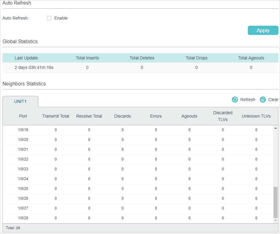
Follow these steps to view LLDP statistics:
1)In the Auto Refresh section, enable the Auto Refresh feature and set the Refresh Rate according to your needs. Click Apply.
2)In the Global Statistics section, view the global statistics of the local device.
|
Last Update |
Displays the time when the statistics updated. |
|
Total Inserts |
Displays the total number of neighbors during latest update time. |
|
Total Deletes |
Displays the number of neighbors deleted by the local device. The port will delet neighbors when the port is disabled or the TTL of the LLDP packets sent by the neighbor is 0. |
|
Total Drops |
Displays the number of neighbors dropped by the local device. Each port can learn a maximum of 80 neighbor device, and the subsquent neighbors will be dropped when the limit is exceeded. |
|
Total Ageouts |
Displays the latest number of neighbors that have aged out on the local device. |
3)In the Neighbors Statistics section, view the statistics of the corresponding port.
|
Transmit Total |
Displays the total number of the LLDP packets sent via the port. |
|
Receive Total |
Displays the total number of the LLDP packets received via the port. |
|
Discards |
Displays the total number of the LLDP packets discarded by the port. |
|
Errors |
Displays the total number of the error LLDP packets received via the port. |
|
Ageouts |
Displays the number of the aged out neighbors that are connected to the port. |
|
TLV Discards |
Displays the total number of the TLVs discarded by the port when receiving LLDP packets. |
|
TLV Unknowns |
Displays the total number of the unknown TLVs included in the received LLDP packets. |
4.2Using CLI
Viewing the Local Info
|
show lldp local-information interface { fastEthernet port | gigabitEthernet port | ten-gigabitEthernet port } View the LLDP details of a specific port or all the ports on the local device. |
Viewing the Neighbor Info
|
show lldp neighbor-information interface { fastEthernet port | gigabitEthernet port | ten-gigabitEthernet port } Display the information of the neighbor device which is connected to the port. |
Viewing LLDP Statistics
|
show lldp traffic interface { fastEthernet port | gigabitEthernet port | ten-gigabitEthernet port } View the statistics of the corresponding port on the local device. |
5.1Using GUI
Choose the menu L2 FEATURES > LLDP > LLDP-MED Config > Local Info to load the following page.
Viewing the Local Info
Figure 5-1 LLDP-MED Local Info
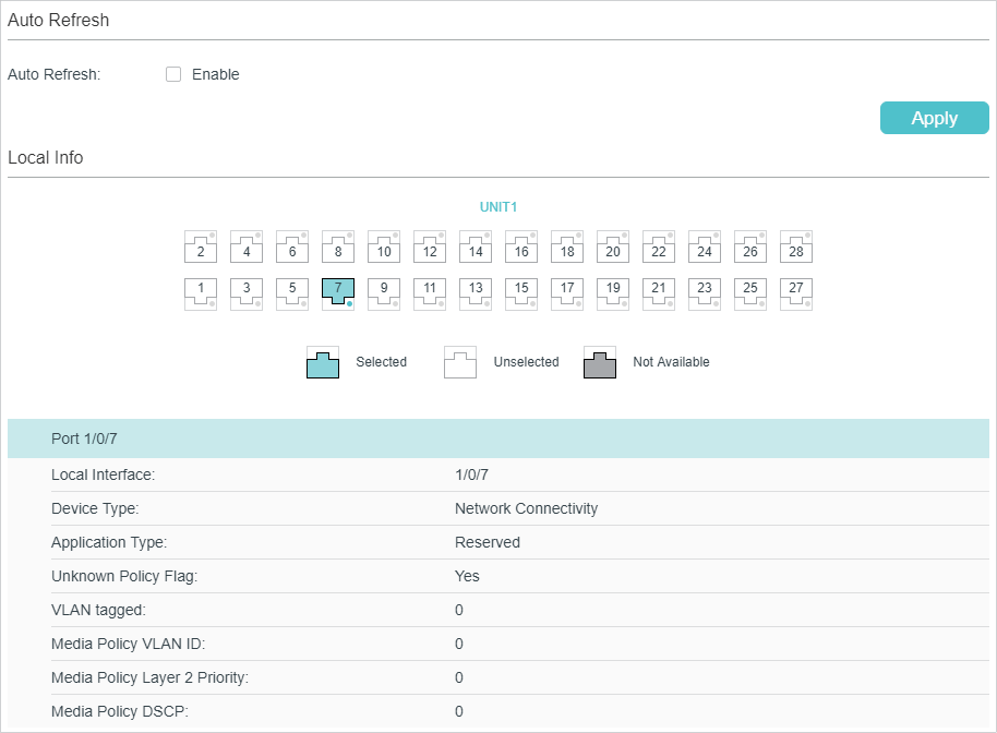
Follow these steps to view LLDP-MED local information:
1)In the Auto Refresh section, enable the Auto Refresh feature and set the Refresh Rate according to your needs. Click Apply.
2)In the LLDP-MED Local Info section, select the desired port and view the LLDP-MED settings.
|
Local Interface |
Displays the local port ID. |
|
Device Type |
Displays the local device type defined by LLDP-MED.LLDP-MED. |
|
Application Type |
Displays the supported applications of the local device. |
|
Unknown Policy Flag |
Displays the unknown location settings included in the network policy TLV. |
|
VLAN tagged |
Displays the VLAN Tag type of the applications, tagged or untagged. |
|
Media Policy VLAN ID |
Displays the 802.1Q VLAN ID of the port. |
|
Media Policy Layer 2 Priority |
Displays the Layer 2 priority used in the specific application. |
|
Media Policy DSCP |
Displays the DSCP value used in the specific application. |
Viewing the Neighbor Info
Choose the menu L2 FEATURES > LLDP > LLDP-MED Config > Neighbor Info to load the following page.
Figure 5-2 LLDP-MED Neighbor Info
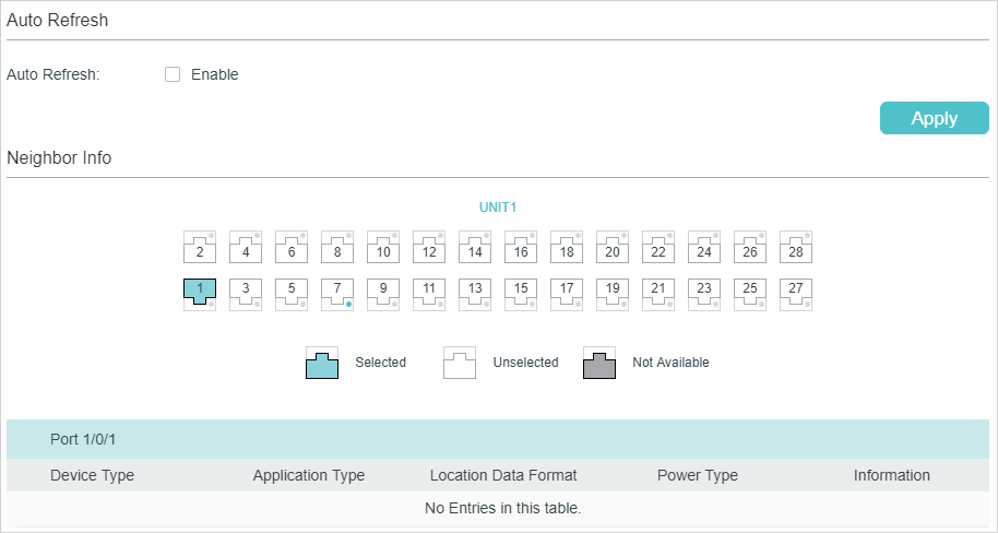
Follow these steps to view LLDP-MED neighgbor information:
1)In the Auto Refresh section, enable the Auto Refresh feature and set the Refresh Rate according to your needs. Click Apply.
2)In the Neighbor Info section, select the desired port and view the LLDP-MED settings.
|
Device Type |
Displays the LLDP-MED device type of the neighbor device. |
|
Application Type |
Displays the application type of the neighbor device. |
|
Location Data Format |
Displays the location type of the neighbor device. |
|
Power Type |
Displays the power type of the neighbor device. |
|
Information |
View more LLDP-MED details of the neighbor device. |
5.2Using CLI
Viewing the Local Info
|
show lldp local-information interface { fastEthernet port | gigabitEthernet port | ten-gigabitEthernet port } View the LLDP details of a specific port or all the ports on the local device. |
Viewing the Neighbor Info
|
show lldp neighbor-information interface { fastEthernet port | gigabitEthernet port | ten-gigabitEthernet port } Display the information of the neighbor device which is connected to the port. |
Viewing LLDP Statistics
|
show lldp traffic interface { fastEthernet port | gigabitEthernet port | tengigabitEthernet port } View the statistics of the corresponding port. |
6.1Configuration Example for LLDP
6.1.1Network Requirements
The network administrator needs view the information of the devices in the company network to know about the link situation and network topology so that he can troubleshoot the potential network faults in advance.
6.1.2Network Topology
Exampled with the following situation:
Port Gi1/0/1 on Switch A is directly connected to port Gi1/0/2 on Switch B. Switch B is directly connected to the PC. The administrator can view the device information using the NMS.
Figure 6-1 LLDP Network Topology
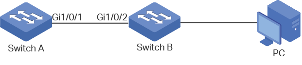
6.1.3Configuration Scheme
LLDP can meet the network requirements. Enable the LLDP feature globally on Switch A and Switch B. Configure the related LLDP parameters on the corresponding ports.
Configuring Switch A and Switch B:
The configurations of Switch A and Switch B are similar. The following introductions take Switch A as an example. Demonstrated with T2600G-28TS, this chapter provides configuration procedures in two ways: using the GUI and using the CLI.
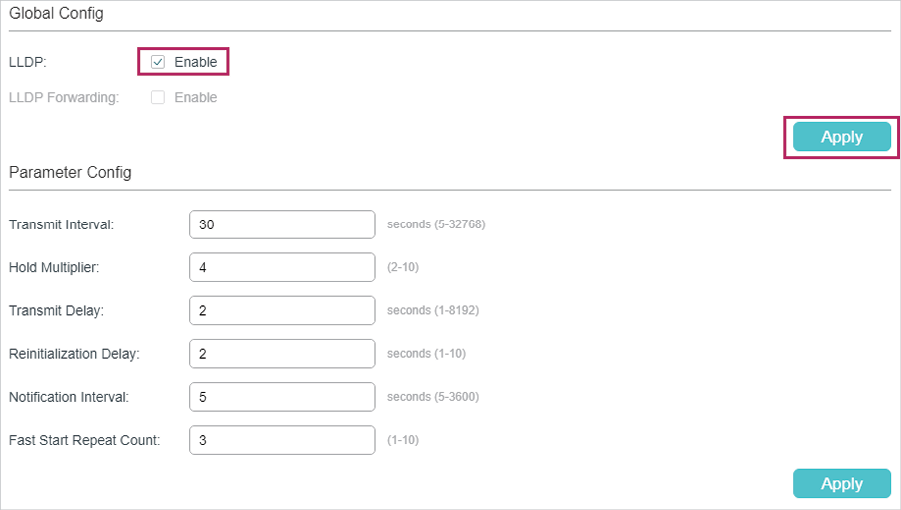
6.1.4Using the GUI
1)Choose the menu L2 FEATURES > LLDP > LLDP Config > Global Config to load the following page. Enable LLDP globally and configure the related parameters. Here we take the default settings as an example.
Figure 6-2 LLDP Global Config
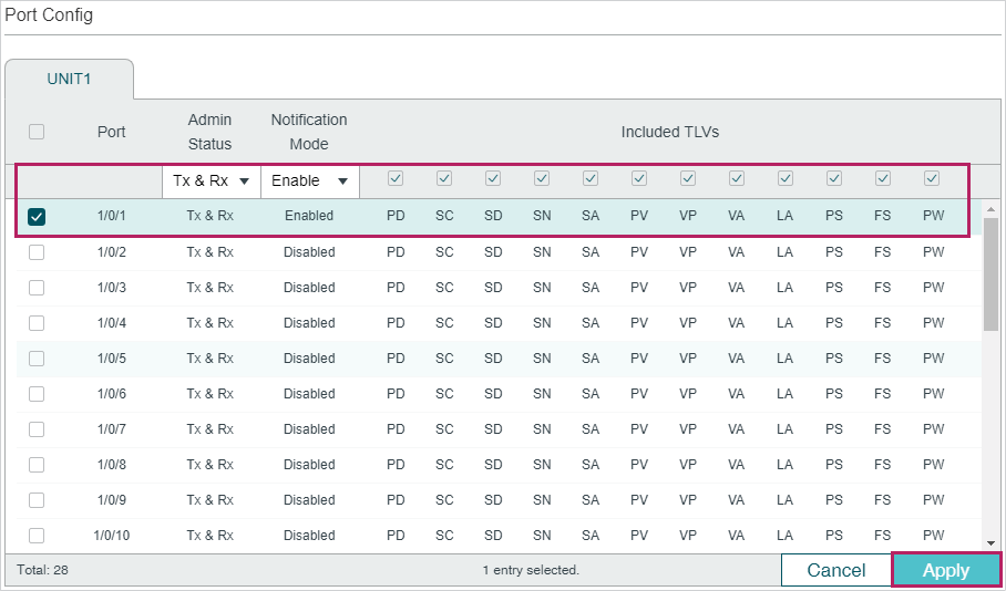
2)Choose the menu L2 FEATURES > LLDP > LLDP Config > Port Config to load the following page. Set the Admin Status of port Gi1/0/1 as Tx&Rx, enable Notification Mode and configure all the TLVs included in the outgoing LLDP packets.
Figure 6-3 LLDP Port Config
6.1.5Using CLI
1)Enable LLDP globally and configure the corresponding parameters.
Switch_A#configure
Switch_A(config)#lldp
Switch_A(config)#lldp hold-multiplier 4
Switch_A(config)#lldp timer tx-interval 30 tx-delay 2 reinit-delay 3 notify-interval 5 fast-count 3
2)Set the Admin Status of port Gi1/0/1 to Tx&Rx, enable Notification Mode and configure all the TLVs included in the outgoing LLDP packets.
Switch_A#configure
Switch_A(config)#interface gigabitEthernet 1/0/1
Switch_A(config-if)#lldp receive
Switch_A(config-if)#lldp transmit
Switch_A(config-if)#lldp snmp-trap
Switch_A(config-if)#lldp tlv-select all
Switch_A(config-if)#end
Switch_A#copy running-config startup-config
Verify the Configurations
3)View LLDP settings globally
Switch_A#show lldp
LLDP Status: Enabled
LLDP Forward Message: Disabled
Tx Interval: 30 seconds
TTL Multiplier: 4
Tx Delay: 2 seconds
Initialization Delay: 2 seconds
Trap Notification Interval: 5 seconds
Fast-packet Count: 3
LLDP-MED Fast Start Repeat Count: 4
4)View LLDP settings on each port
Switch_A#show lldp interface gigabitEthernet 1/0/1
LLDP interface config:
gigabitEthernet 1/0/1:
Admin Status: TxRx
SNMP Trap: Enabled
TLV Status
--- ------
Port-Description Yes
System-Capability Yes
System-Description Yes
System-Name Yes
Management-Address Yes
Port-VLAN-ID Yes
Protocol-VLAN-ID Yes
VLAN-Name Yes
Link-Aggregation Yes
MAC-Physic Yes
Max-Frame-Size Yes
Power Yes
LLDP-MED Status: Disabled
TLV Status
--- ------
Network Policy Yes
Location Identification Yes
Extended Power Via MDI Yes
Inventory Management Yes
5)View the Local Info
Switch_A#show lldp local-information interface gigabitEthernet 1/0/1
LLDP local Information:
gigabitEthernet 1/0/1:
Chassis type: MAC address
Chassis ID: 00:0A:EB:13:23:97
Port ID type: Interface name
Port ID: GigabitEthernet1/0/1
Port description: GigabitEthernet1/0/1 Interface
TTL: 120
System name: T2600G-28TS
System description: JetStream 24-Port Gigabit L2 Managed Switch with
4 SFP Slots
System capabilities supported: Bridge Router
System capabilities enabled: Bridge Router
Management address type: ipv4
Management address: 192.168.0.226
Management address interface type: IfIndex
Management address interface ID: 1
Management address OID: 0
Port VLAN ID(PVID): 1
Port and protocol VLAN ID(PPVID): 0
Port and protocol VLAN supported: Yes
Port and protocol VLAN enabled: No
VLAN name of VLAN 1: System-VLAN
Protocol identity:
Auto-negotiation supported: Yes
Auto-negotiation enabled: Yes
OperMau: speed(1000)/duplex(Full)
Link aggregation supported: Yes
Link aggregation enabled: No
Aggregation port ID: 0
Power port class: PD
PSE power supported: No
PSE power enabled: No
PSE pairs control ability: No
Maximum frame size: 1518
LLDP-MED Capabilities: Capabilities
Network Policy
Location Identification
Inventory
Device Type: Network Connectivity
Application type: Reserved
Unknown policy: Yes
Tagged: No
VLAN ID: 0
Layer 2 Priority: 0
DSCP: 0
Location Data Format: Civic Address LCI
- What: Switch
- Country Code: CN
Hardware Revision: T2600G-28TS 3.0
Firmware Revision: Reserved
Software Revision: 3.0.0 Build 20170918 Rel.71414(s)
Serial Number: Reserved
Manufacturer Name: TP-Link
Model Name: T2600G-28TS 3.0
Asset ID: unknown
6)View the Neighbor Info
Switch_A#show lldp neighbor-information interface gigabitEthernet 1/0/1
LLDP Neighbor Information:
gigabitEthernet 1/0/1:
Neighbor index 1:
Chassis type: MAC address
Chassis ID: 00:0A:EB:13:18:2D
Port ID type: Interface name
Port ID: GigabitEthernet1/0/2
Port description: GigabitEthernet1/0/2 Interface
TTL: 120
System name: T1600G-52PS
System description: JetStream 48-Port Gigabit Smart
PoE Switch with 4 SFP Slots
System capabilities supported: Bridge Router
System capabilities enabled: Bridge Router
Management address type: ipv4
Management address: 192.168.0.1
Management address interface type: IfIndex
Management address interface ID: 1
Management address OID: 0
Port VLAN ID(PVID): 1
Port and protocol VLAN ID(PPVID): 0
Port and protocol VLAN supported: Yes
Port and protocol VLAN enabled: No
VLAN name of VLAN 1: System-VLAN
Protocol identity:
Auto-negotiation supported: Yes
Auto-negotiation enabled: Yes
OperMau: speed(1000)/duplex(Full)
Link aggregation supported: Yes
Link aggregation enabled: No
Aggregation port ID: 0
Power port class: PSE
PSE power supported: Yes
PSE power enabled: Yes
PSE pairs control ability: No
6.2Example for LLDP-MED
6.2.1Network Requirements
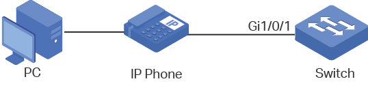
As the following figure shows, an IP phone and a PC are both connected to port 1/0/1 of the switch. It is required that the voice data stream is sent to VLAN2 and other untagged data stream is sent to the default VLAN1.
Figure 6-1 LLDP-MED Network Topology
6.2.2Configuration Scheme
LLDP-MED allows the switch to send its Auto VoIP information to the IP phones for auto-configuration. In this example, you can configure Auto VoIP and LLDP-MED to meet the network requirements.
The configuration overview is as follows:
1)Create VLAN2 for the voice data and keep the PVID of port 1/0/1 as the default value 1. In this way, all the untagged packets from the PC are sent to VLAN1; all the packets with VLAN Tag 2 from the IP phone are sent to VLAN2.
2)Configure Auto VoIP on port 1/0/1.
3)Enable LLDP globally.
4)Configure LLDP-MED on port 1/0/1.
Demonstrated with T1600G-28TS, this chapter provides configuration procedures in two ways: using the GUI and using the CLI.
6.2.3Using the GUI
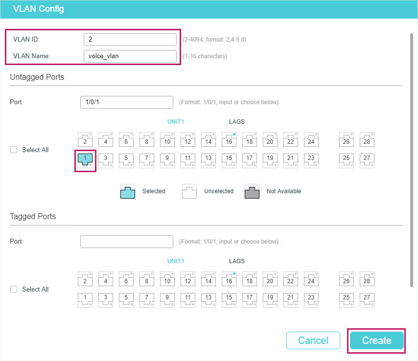
1)Choose the menu L2 FEATURES > VLAN > 802.1Q VLAN > VLAN Config and click  to load the following page. Specify VLAN ID as 2, give a VLAN name, and select port 1/0/1 as untagged member port. Click Create.
Figure 6-2 VLAN Config
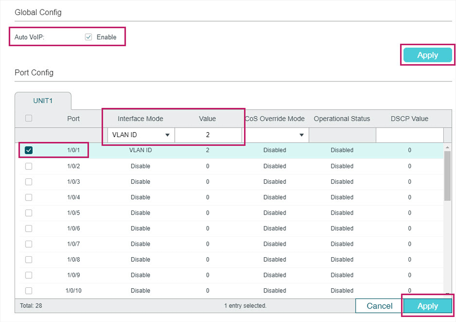
2)Choose the menu QoS > Auto VoIP to load the following page. Select port 1/0/1, configure the interface mode as VLAN ID and set the VLAN ID value as 2. Click Apply.
Figure 6-3 Auto VoIP Config
3)Choose the menu L2 FEATURES > LLDP > LLDP Config > Global Config to load the following page. Enable LLDP globally and click Apply.
Figure 6-4 LLDP Global Config
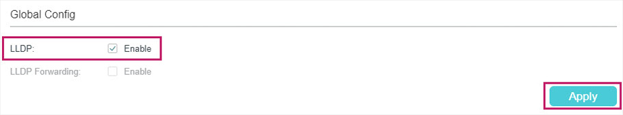
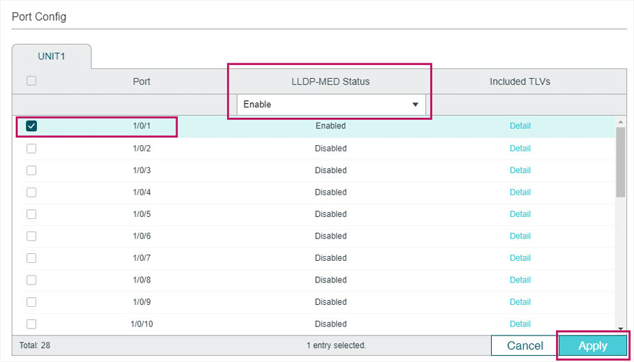
4)Choose the menu L2 FEATURES > LLDP > LLDP Config >Global Config > Port Config to load the following page. Enable LLDP-MED on port 1/0/1 and click Apply.
Figure 6-5 LLDP-MED Config
5)Click  to save the settings.
6.2.4Using CLI
1)Create VLAN2 and add untagged port 1/0/1 to VLAN2.
Switch#configure
Switch(config)#vlan 2
Switch(config-vlan)#name voice_vlan
Switch(config-vlan)#exit
Switch(config)#interface gigabitEthernet 1/0/1
Switch(config-if)#switch general allowed vlan 2 untagged
Switch(config-if)#exit
2)Enable Auto VoIP globally.
Switch(config)#auto-voip
3)Configure Auto VoIP. On port 1/0/1, configure the interface mode as VLAN ID and set the VLAN ID value as 2.
Switch(config)#interface gigabitEthernet 1/0/1
Switch(config-if)#auto-voip 2
Switch(config-if)#exit
4)Enable LLDP globally.
Switch(config)#lldp
5)Enable LLDP-MED on port 1/0/1.
Switch(config)#interface gigabitEthernet 1/0/1
Switch(config-if)#lldp med-status
Switch(config-if)#end
Switch#copy running-config startup-config
Verify the Configurations
View VLAN settings:
Switch#show vlan
VLAN Name Status Ports
----- -------------------- --------- ----------------------------------------
1 System-VLAN active Gi1/0/1, Gi1/0/2, Gi1/0/3, Gi1/0/4,
Gi1/0/5, Gi1/0/6, Gi1/0/7, Gi1/0/8,
Gi1/0/9, Gi1/0/10, Gi1/0/11, Gi1/0/12,
Gi1/0/13, Gi1/0/14, Gi1/0/15, Gi1/0/16,
Gi1/0/17, Gi1/0/18, Gi1/0/19, Gi1/0/20,
Gi1/0/21, Gi1/0/22, Gi1/0/23, Gi1/0/24,
Gi1/0/25, Gi1/0/26, Gi1/0/27, Gi1/0/28
2 voice_vlan active Gi1/0/1
View VoIP settings:
Switch#show auto-voip interface
Interface.Gi1/0/1
Auto-VoIP Interface Mode. Enabled
Auto-VoIP VLAN ID. 2
Auto-VoIP COS Override. False
Auto-VoIP DSCP Value. 0
Auto-VoIP Port Status. Enabled
...
View global LLDP settings:
Switch_A#show lldp
LLDP Status: Enabled
LLDP Forward Message: Disabled
...
View LLDP-MED settings on port 1/0/1:
Switch_A#show lldp interface gigabitEthernet 1/0/1
LLDP interface config:
gigabitEthernet 1/0/1:
...
LLDP-MED Status: Enabled
TLV Status
--- ------
Network Policy Yes
Location Identification Yes
Extended Power Via MDI Yes
Inventory Management Yes
Default settings of LLDP are listed in the following tables.
Default LLDP Settings
Table 7-1Default LLDP Settings
|
Parameter |
Default Setting |
|
LLDP |
Disable |
|
LLDP Forward Message |
Disable |
|
Transmit Interval |
30 seconds |
|
Hold Multiplier |
4 |
|
Transmit Delay |
2 seconds |
|
Reinitialization Delay |
2 seconds |
|
Notification Interval |
5 seconds |
|
Fast Start Repeat Count |
3 |
Table 7-2Default LLDP Settings on the Port
|
Parameter |
Default Setting |
|
Admin Status |
Tx&Rx |
|
Notification Mode |
Disable |
|
Included TLVs |
All |
Default LLDP-MED Settings
Table 7-3Default LLDP-MED Settings
|
Parameter |
Default Setting |
|
Fast Start Repeat Count |
4 |
|
LLDP-MED Status (port) |
Disable |
|
Included TLVs |
All |