How to Use RS-485 controller for PTZ control
Contents
Control Signal Connection Diagram
RS-485 Physical Wiring Example
Introduction
RS-485 is a communication port. It can control the camera via back-end device when the information of RS-485 is set in accordance with that of the back-end coding device.
Requirements
- VIGI PTZ Camera with RS-485 Port
- RS-485 controller (for example, a joystick keyboard with an RS-485 interface that supports the PELCO-D/P protocol)
Hardware Setup
Wiring Instructions
The RS-485 interface uses a two-wire differential communication method, providing two terminals: 485+ and 485-.
A communication cable is required for RS-485 communication.
Connect the RS-485 cable from the PTZ camera to the RS-485 port on the RS-485 controller. and ensure the polarity matches:
- 485+ → 485+
- 485− → 485−
It is recommended to use a twisted pair cable for wiring to ensure stable communication.
Control Signal Connection Diagram
The control signal connection diagram is shown below.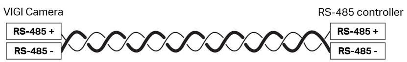
RS-485 Physical Wiring Example
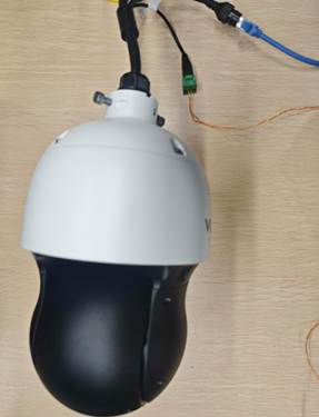
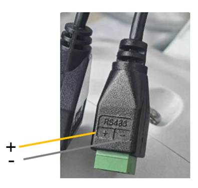
RS-485 Port on Camera (Connect to + and −)
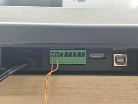
RS-485 Port on Controller (Connect to + and −)
Note: On some RS-485 controllers, the positive and negative terminals may be labeled as A/B instead of +/−. The definition of A/B polarity may vary among manufacturers, so it is recommended to check the controller’s manual before connecting.
Configuration
Configuration for RS-485
Step 1. Ensure the IPC is properly powered on and connected to the network. Then access the IPC web interface using the camera’s IP address and log in.
Step 2. Navigate to Settings > PTZ > RS-485, configure the RS-485 parameters, and click Apply to save the settings.
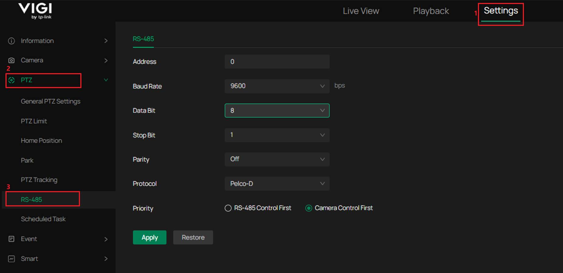
The following parameters can be configured for RS-485 communication.
- Address
Range: 0–255. Default: 0.
The PTZ address of the IPC. The address configured on the external controller must match the IPC address; otherwise, the controller cannot control the IPC. - Baud Rate
Options: 1200, 2400, 4800, 9600, 19200, 38400, 57600, 115200. Default: 9600.
The baud rate must match the baud rate configured on the external controller. - Data Bit
Options: 5, 6, 7, 8. Default: 8.
Defines the number of data bits used for RS-485 communication. The value must match the setting on the external controller. - Stop Bit
Options: 1, 2. Default: 1.
Defines the number of stop bits used for RS-485 communication. The value must match the setting on the external controller. - Parity
Options: On, Off. Default: Off.
Defines whether parity checking is enabled for RS-485 communication. The value must match the setting on the external controller. - Protocol
Options: Pelco-D, Pelco-P, Auto. Default: Pelco-D.
When the IPC is set to Pelco-D or Pelco-P, the protocol configured on the external controller must be the same as that on the IPC; otherwise, the controller cannot control the IPC. When the IPC is set to Auto, the external controller can use either Pelco-D or Pelco-P to control the IPC. - Priority
Options: RS-485 Control First, Camera Control First. Default: Camera Control First.
Determines whether RS-485 controller commands or PTZ control from the camera Web interface or client software (such as VIGI APP, VMS) has higher priority.
When Camera Control First is selected, PTZ control from the Web interface or client software takes priority. During this period, commands from the RS-485 controller will not take effect. After the Web or client control stops, the RS-485 controller can take control again after about 10 seconds.
When RS-485 Control First is selected, the RS-485 controller has priority, and the control behavior is the reverse of the above.
Note:
Data Bit, Stop Bit, and Parity are serial communication parameters. They must match the configuration of the external controller; otherwise, communication may fail or incorrect data may be received.
Step 3. After the wiring and configuration are completed, operate the PTZ functions according to the definitions on the RS-485 controller. The controller can be used to control the IPC to move in eight directions (left, right, up, down, upper-left, lower-left, upper-right, lower-right) and perform zoom in and zoom out. It also supports focus adjustment, iris adjustment, preset calling/setting/deleting, enabling Patrol, and enabling Pattern Scan.
The following table lists the corresponding command names defined in the Pelco protocol for common control functions:
|
Function |
Pelco Command / Field Name |
|
Move Left |
Pan Left |
|
Move Right |
Pan Right |
|
Move Up |
Tilt Up |
|
Move Down |
Tilt Down |
|
Move Upper-Left |
Pan Left + Tilt Up |
|
Move Lower-Left |
Pan Left + Tilt Down |
|
Move Upper-Right |
Pan Right + Tilt Up |
|
Move Lower-Right |
Pan Right + Tilt Down |
|
Zoom In |
Zoom Tele |
|
Zoom Out |
Zoom Wide |
|
Focus Near |
Focus Near |
|
Focus Far |
Focus Far |
|
Iris Open |
Iris Open |
|
Iris Close |
Iris Close |
|
Set Preset |
Set Preset |
|
Call Preset |
Go To Preset / Call Preset |
|
Delete Preset |
Clear Preset |
|
Start Patrol Scan |
Starts the patrol scan |
|
Run Pattern |
Starts executing a pre-configured pattern |
|
Stop |
Stops the current PTZ movement or terminates the active patrol or pattern scan |
Note:
The command names listed in the table follow the Pelco protocol standard fields. The actual command implementation may vary depending on the controller manufacturer.
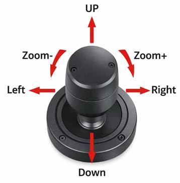
Note:
This diagram is for reference only. The specific operation methods depend on the definitions provided by the controller manufacturer.
Verification
After the wiring and configuration are completed, the IPC can be controlled through the RS-485 controller. The following video demonstrates the controller operating the Pan/Tilt functions of the IPC, including left/right, up/down, and diagonal movements.
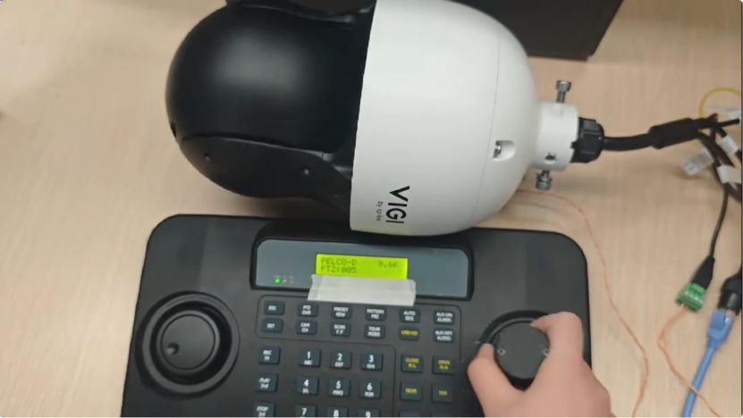
Video Download Link: RS-485 PTZ Control Demo Video
Conclusion
You have successfully configured the RS-485 connection between the IPC and the controller, and the IPC can now be controlled through the RS-485 controller.
Get to know more details of each function and configuration please go to Download Center to download the manual of your product.
QA
Q1: The PTZ controller cannot control the camera and there is no response at all. What could be the cause?
A1:
- Check whether the RS-485 wiring is correct.
Confirm that the controller’s TXD+ / TXD− are connected to the camera’s RS-485+ / RS-485− respectively.
If the A/B polarity is reversed, the device will typically have no response. - Check whether the communication parameters are consistent.
The controller and the camera must use the same serial communication parameters, such as:
Baud Rate, Data Bit, Stop Bit, Parity - Check whether the control protocol is consistent.
Common protocols include Pelco-D and Pelco-P. If the protocols do not match, the camera will not respond to control commands.
Q2: PTZ control works, but the response is sometimes slow.
A2: This may be related to the RS-485 bus quality or wiring conditions. It is recommended to use shielded twisted pair cables and avoid routing the cable parallel to high-voltage power lines.
Q3: The wiring is correct, but the PTZ control direction is abnormal (for example, the camera turns right when the controller command is left).
A3: This may be caused by an incorrect protocol setting. Different protocols use different command formats. Please confirm that the control protocol configured on the controller matches that of the camera.
Q4: Why is it recommended to use shielded twisted pair cables for RS-485 connections?
A4: RS-485 uses differential signal transmission. Twisted pair cables help reduce external electromagnetic interference, while the shielding layer further improves communication stability.
Is this faq useful?
Your feedback helps improve this site.
TP-Link Community
Still need help? Search for answers, ask questions, and get help from TP-Link experts and other users around the world.