


How to Configure M-LAG on Omada Switches
Contents
Configuration for M-LAG System Handling Layer 2 Forwarding Only
Configuration for M-LAG System Handling Layer 3 Forwarding
Introduction
M-LAG, short for Multi-Chassis Link Aggregation Group, also known as MC-LAG, is a mechanism designed to achieve LAG across multiple devices.
When operating M-LAG, the two devices involved logically function as a single entity for traffic forwarding. In terms of loop prevention and device redundancy, it delivers effects comparable to stacking, enabling both link redundancy through bundling and redundancy against single-point device failures. However, it differs significantly from stacking: in a stacking system, all the units' controls are merged into a single master unit, whereas in an M-LAG system, the power of the two devices remains independent, thereby preventing a single point of failure from impacting the entire system.
Moreover, stacking often results in prolonged packet loss due to upgrades (which require a holistic system-wide upgrade) or replacements. In contrast, M-LAG allows for individual traffic switching on the two devices, followed by sequential upgrades or replacements, ensuring business continuity throughout the process. As campus network devices require higher standards, with increasingly stringent requirements for business interruption time and network reliability, M-LAG is essential for providing efficient and reliable virtualization capabilities.
Before we go to the detailed configuration of M-LAG, the following key terms and their definitions should be introduced and understood in advance:
- Peer Device: The two switches operating the same M-LAG are referred to as peer devices. Unlike stacking, when operating normally, the two switches have the same role, with no significant distinction between “master” and “member”; that’s why they are called peer devices.
- M-LAG Domain: The domain of M-LAG, including the dual-active system formed by two peer switches and the link transmitting negotiation or control messages between them.
- Peer-Link: The direct link connecting two M-LAG peer switches within the M-LAG Domain, responsible for exchanging M-LAG controlling information, synchronizing table entries, and transmitting part of the forwarded service traffic.
- DAD: Short for Dual-Active Detection, it is a mechanism designed to identify and mitigate "dual-active" scenarios, where both M-LAG peer devices mistakenly operate as active due to a failure in the peer-link or synchronization. When the peer link fails, the two peers are unable to synchronize. The M-LAG system will split; this could cause chaos in the network if the two peers continue to run without synchronizing with each other. With DAD, it could detect if the M-LAG peer switch is still alive after splitting or the so-called “brain-splitting” and shut one of the peer’s M-LAG operations down to keep the traffic forwarding clear in the M-LAG domain.
- DAD-Link: The direct link connecting two M-LAG peer switches to perform DAD. It is a pure IP-based detection, so the ports involving DAD-link will act as routed ports.
- M-LAG Member Port: The ports on M-LAG peer devices connect to clients and form the LAG between clients and M-LAG peer devices.
- Orphan Port: The ports or LAGs that are not configured as M-LAG member ports. Connecting to an orphan port will not join the traffic to the M-LAG system, and the redundancy cannot be ensured.
- Dual-Homed Access: The connecting method where the client device connects to both M-LAG peer devices within the M-LAG domain and forms an LAG across the peer devices.
- Single-Homed Access: The connecting method where the client device connects to only one M-LAG peer device within the M-LAG domain and does not form an LAG across peer devices. The redundancy of single-homed devices cannot be ensured.
Please note that in M-LAG deployments, the peer-link primarily facilitates the synchronization of dynamic table entries, such as MAC address tables and ARP tables, as well as other runtime state information, to ensure consistent traffic forwarding and loop prevention across the M-LAG peer devices. However, M-LAG does not automatically synchronize configurations between the peers. Therefore, to achieve operational consistency for M-LAG-related features, identical configurations must be manually applied to both M-LAG peer devices. Note that this requirement applies only to specific M-LAG-relevant settings—such as peer-link interfaces, LAG or LACP parameters, global and port IGMP snooping status, and redundancy protocols. It’s not the entire switch configuration, which allows for the independent management of unrelated features on each device.
Requirements
- Omada S6500/S7500 Switches
Configuration
In the following section, we provide a simple example of M-LAG configuration on Omada Pro L3 switches. The configuration will be provided based on two scenarios:
The first scenario is that the M-LAG system will not handle Layer 3 forwarding or IP forwarding, only providing Layer 2 forwarding and redundancy.
The second scenario is that the M-LAG system will handle Layer 3 forwarding, providing both Layer 2 and Layer 3 redundancy.
Configuration for M-LAG System Handling Layer 2 Forwarding Only
The topology for this scenario goes like this:
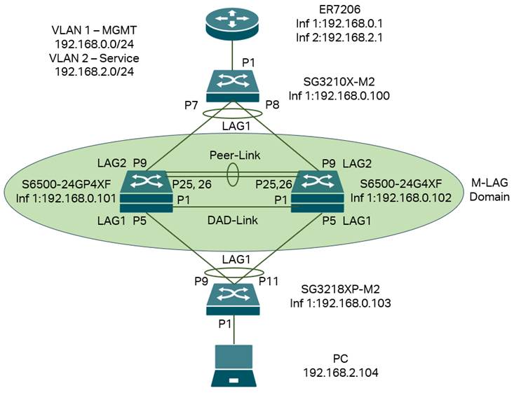
In this scenario, we have VLAN 1 for management, so every device have IP address on interface VLAN 1 for management, but for service VLAN running traffic which is VLAN 2, only the PC and router have interface with IP addresses in this VLAN, all the switches in between, including the M-LAG system don’t need interface in VLAN 2 as they are only handling layer 2 forwarding. All the IP addresses in this example will be configured statically; alternatively, you can use DHCP as needed.
Briefly, we need to connect the devices, configure the VLAN, interfaces, and IP addresses, enable M-LAG on peer devices, configure peer-link, DAD-link, and member ports, as well as the LAGs between M-LAG peer devices and other devices. Additionally, we need to configure VLAN status on all ports and LAGs.
Step 1. Power up all devices, but don’t connect the cables yet, as the LAGs, Peer-Link, and DAD-Link are not yet configured. Connecting all the wires may cause conflicts and chaos in the topology.
Step 2. Configure the IP address of interface VLAN 1 on all switches. Take the S6500-24GP4XF as an example; the IP address will be 192.168.0.101. Commands as follows:
interface vlan 1
ip address 192.168.0.101 255.255.255.0
exit
This will configure the IP address of interface VLAN 1 statically and return to the global config view. For all other switches, configure accordingly. You can also configure the IP address allocation mode to use DHCP.
Step 3. Create VLAN 2 and interface VLAN 2 on the gateway, then configure the IP address. Additionally, configure VLAN 2 as tagged on the port connecting to the switches.
Step 4. Create VLAN 2 on all switches and configure the port VLAN status. As the LAGs are not yet configured, we only need to configure the port VLAN for ports that do not involve LAG. Among the ports, for ports connecting to endpoint devices like PCs and APs, add them untagged into VLAN 2; for ports connecting between switches and the gateway, add them tagged into VLAN 2.
In the example topology, we need to add port 1 of SG3218XP-M2 as untagged into VLAN 2 and add port 1 of SG3210X-M2 as tagged into VLAN 2. Commands as follows:
For all switches:
vlan 2
exit
This will create VLAN 2 on all switches.
For SG3218XP-M2:
interface two-gigabitEthernet 1/0/1switchport general allowed vlan 2 untagged
no switchport general allowed vlan 1
switchport pvid 2
exit
This will make port 1 on SG3218XP-M2 the access port of VLAN 2, so all endpoint devices connected will send traffic in VLAN 2.
For SG3210X-M2:
interface two-gigabitEthernet 1/0/1
switchport general allowed vlan 2 tagged
exit
Step 5. Enable M-LAG on both peer switches, configure the peer-link and DAD-link. For the peer-link, only the uplink ports running at the highest port speed could be used, which means the media used to act as the peer-link must match the highest speed of the uplink ports. For example, if the uplink ports are 10G SFP+ ports, a 1G DAC cannot be used to form the peer link. You can also configure multiple links as peer links by setting multiple ports as peer-link ports. For the DAD-link, as we mentioned earlier, it is a purely IP-based link, and the ports on both sides will act as routed ports. Therefore, we need to specify the peer and source IP addresses when configuring the DAD-link. Please note that when enabling M-LAG, a domain ID must be configured. The domain ID set on M-LAG peer devices must be the same; otherwise, the M-LAG cannot be established. Commands as follows:
On S6500-24GP4XF:
mlag enable 1
mlag domain 1
interface 1/0/25-26
dad interface 1/0/1
dad param peer-ip-address 192.168.10.2 src-ip-address 192.168.10.1
dad enable
exit
On S6500-24G4XF:
mlag enable 1
mlag domain 1
interface 1/0/25-26
dad interface 1/0/1
dad param peer-ip-address 192.168.10.1 src-ip-address 192.168.10.2
dad enable
exit
We have now finished configuring peer-link and DAD-link, and connected all the cables according to the topology.
Step 6. Create all LAGs needed on the switches and add them to VLAN 2. Since the LAGs are connecting between the switches, we need to tag them into VLAN 2. As M-LAG is creating LAG across devices, we will configure LAG separately on both M-LAG peer switches. The ports within the LAG with the same LAG ID will be considered the same LAG across devices and will work together to connect to other devices. These LAGs will be configured as M-LAG member ports, and the traffic entering from M-LAG member ports will be forwarded according to M-LAG rules. Commands as follows:
For SG3218XP-M2:
interface range two-gigabitEthernet 1/0/9,1/0/11
channel-group 1 mode passive
exit
interface port-channel 1
switchport general allowed vlan 2 tagged
exit
For SG3210X-M2:
interface range two-gigabitEthernet 1/0/7-8
channel-group 1 mode passive
exit
interface port-channel 1
switchport general allowed vlan 2 tagged
exit
For S6500-24GP4XF:
interface gigabitEthernet 1/0/5
channel-group 1 mode active
exit
interface gigabitEthernet 1/0/9
channel-group 2 mode active
exit
interface port-channel 1
switchport general allowed vlan 2 tagged
mlag
exit
interface port-channel 2
switchport general allowed vlan 2 tagged
mlag
exit
For S6500-24G4XF:
interface gigabitEthernet 1/0/5
channel-group 1 mode active
exit
interface gigabitEthernet 1/0/9
channel-group 2 mode active
exit
interface port-channel 1
switchport general allowed vlan 2 tagged
mlag
exit
interface port-channel 2
switchport general allowed vlan 2 tagged
mlag
exit
Currently, all the LAGs have been configured, and all the cables can be connected according to the example topology.
Up to this point, we have completed the configuration for the M-LAG system, which handles only Layer 2 forwarding, according to the example topology.
Configuration for M-LAG System Handling Layer 3 Forwarding
The topology for this scenario goes like this:
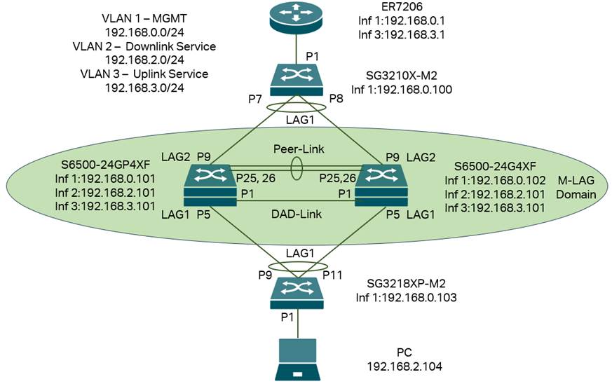
In this scenario, we have VLAN 1 for management, so every device have IP address on interface VLAN 1 for management, but for service VLAN running traffic, we separate them into two parts as the M-LAG system will handle layer 3 forwarding, for the downlink part of M-LAG system, use VLAN 2 as service VLAN, for the uplink part, use VLAN 3 as service VLAN.
For both M-LAG peer devices, they need to have interfaces in VLANs 1, 2, and 3 for both management and Layer 3 forwarding between the uplink and downlink. For other switches, as they don’t need to handle Layer 3 forwarding, only the VLAN 1 interface for management is required. All the IP addresses in this example will be configured statically; alternatively, you can use DHCP as needed.
Briefly, we need to connect the devices, configure the VLAN, interfaces, and IP addresses, enable M-LAG on peer devices, configure peer-link, DAD-link, and member ports, as well as the LAGs between peer devices and other devices. Additionally, we need to configure VLAN status on all ports and LAGs.
Step 1. Power up all devices, but don’t connect the cables yet, as the LAGs, Peer-Link, and DAD-Link are not yet configured. Connecting all the wires may cause conflicts and chaos in the topology.
Step 2. Configure the IP address of interface VLAN 1 on all switches, then configure VLANs 2 and 3 on both M-LAG peer devices. Take the S6500-24GP4XF as an example; the IP address will be 192.168.0.101. Commands as follows:
interface vlan 1
ip address 192.168.0.101 255.255.255.0
exit
This will configure the IP address of interface VLAN 1 statically and return to the global config view. For all other switches, configure accordingly. You can also configure the IP address allocation mode as DHCP. For other switches, configure accordingly for different IP addresses.
Step 3. Create VLAN 3 and interface VLAN 3 on the gateway, and configure the IP address. Also, configure VLAN 3 as tagged on the port connecting to the switches. Additionally, the gateway lacks information about the VLAN 2 network. To communicate, we also need to configure a static route on the gateway, with the following details: destination 192.168.2.0/24, next hop 192.168.3.101, and interface VLAN 3.
Step 4. Create VLANs 2 and 3 on the switches, then configure the IP addresses of the VLAN interfaces according to the example topology and set the port VLAN status. For this example topology, create VLAN 2 on SG3218XP-M2 and VLAN 3 on SG3210X-M2. Additionally, create both VLAN 2 and VLAN 3 on S6500-24GP4XF and S6500-24G4XF.
As the LAGs are not yet configured, we only need to configure the port VLAN for ports that do not involve LAG. For ports connecting to endpoint devices, such as PCs and APs, add them untagged to the VLAN. For ports connecting between switches and the gateway, add them to the VLAN.
In the example topology, we need to add port 1 of SG3218XP-M2 as untagged into VLAN 2 and add port 1 of SG3210X-M2 as tagged into VLAN 3. Commands as follows:
For SG3218XP-M2:
vlan 2
exit
interface two-gigabitEthernet 1/0/1
switchport general allowed vlan 2 untagged
no switchport general allowed vlan 1
switchport pvid 2
exit
This will make port 1 on SG3218XP-M2 the access port of VLAN 2, so all endpoint devices connected will send traffic in VLAN 2.
For SG3210X-M2:
vlan 3
exit
interface two-gigabitEthernet 1/0/1
switchport general allowed vlan 3 tagged
exit
For S6500-24GP4XF:
vlan 2-3
exit
interface vlan 2
ip address 192.168.2.101 255.255.255.0
exit
interface vlan 3
ip address 192.168.3.101 255.255.255.0
exit
For S6500-24G4XF:
vlan 2-3
exit
interface vlan 2
ip address 192.168.2.101 255.255.255.0
exit
interface vlan 3
ip address 192.168.3.101 255.255.255.0
exit
Note: As the M-LAG system handles layer 3 forwarding via interfaces VLAN 2 and 3, they will act as one device during forwarding. Therefore, the IP addresses for interfaces VLAN 2 and 3 on both M-LAG peer devices should be the same, providing layer 3 redundancy similar to VRRP.
Step 5. Enable M-LAG on both peer devices, configure the peer-link and DAD-link. For the peer-link, only the uplink ports running at the highest port speed could be used, which means the media used to act as the peer-link must match the highest speed of the uplink ports. For example, if the uplink ports are 10G SFP+ ports, a 1G DAC cannot be used to form the peer link. You can also configure multiple links as peer links by setting multiple ports as peer-link ports. For the DAD-link, as we mentioned earlier, it is a purely IP-based link, and the ports on both sides will act as routed ports. Therefore, we need to specify the peer and source IP addresses when configuring the DAD-link. Please note that when enabling M-LAG, a domain ID must be configured. The domain ID set on M-LAG peer devices must be the same; otherwise, the M-LAG cannot be established. Commands as follows:
On S6500-24GP4XF:
mlag enable 1
mlag domain 1
interface 1/0/25-26
dad interface 1/0/1
dad param peer-ip-address 192.168.10.2 src-ip-address 192.168.10.1
dad enable
exit
On S6500-24G4XF:
mlag enable 1
mlag domain 1
interface 1/0/25-26
dad interface 1/0/1
dad param peer-ip-address 192.168.10.1 src-ip-address 192.168.10.2
dad enable
exit
We have now finished configuring peer-link and DAD-link, and connected all the cables according to the topology.
Step 6. Create all LAGs needed on the switches and add them to VLAN 2 or 3. Since the LAGs are connecting between the switches, we need to tag them in the VLANs. As M-LAG is creating LAG across devices, we will configure LAG separately on both peer switches, the ports within the LAG with same LAG ID will be counted as the same LAG across device and work together to connect to other devices, these LAGs will be configured as M-LAG member ports, the traffic entering from M-LAG member ports will be forwarded according to M-LAG rules. Commands as follows:
For SG3218XP-M2:
interface range two-gigabitEthernet 1/0/9,1/0/11
channel-group 1 mode passive
exit
interface port-channel 1
switchport general allowed vlan 2 tagged
exit
For SG3210X-M2:
interface range two-gigabitEthernet 1/0/7-8
channel-group 1 mode passive
exit
interface port-channel 1
switchport general allowed vlan 3 tagged
exit
For S6500-24GP4XF:
interface gigabitEthernet 1/0/5
channel-group 1 mode active
exit
interface gigabitEthernet 1/0/9
channel-group 2 mode active
exit
interface port-channel 1
switchport general allowed vlan 2 tagged
mlag
exit
interface port-channel 2
switchport general allowed vlan 3 tagged
mlag
exit
For S6500-24G4XF:
interface gigabitEthernet 1/0/5
channel-group 1 mode active
exit
interface gigabitEthernet 1/0/9
channel-group 2 mode active
exit
interface port-channel 1
switchport general allowed vlan 2 tagged
mlag
exit
interface port-channel 2
switchport general allowed vlan 3 tagged
mlag
exit
Currently, all the LAGs have been configured, and all the cables can be connected according to the example topology.
Up to this point, we have completed the configuration for the M-LAG system handling Layer 3 forwarding according to the example topology.
Verification
After finishing the configuration, we could verify the link connection via ping from the PC to the gateway:
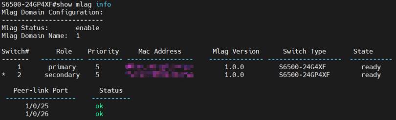
To verify if the M-LAG is working normally, use the command “show mlag info” to check the peer devices in this M-LAG system and peer-link status:
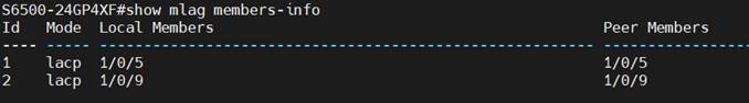
Use the command “show mlag members-info” to check the member ports' status of this M-LAG system:
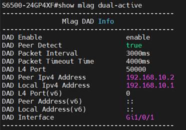
Use the command “show mlag dual-active” to check the DAD status of this M-LAG system:
Make an extended ping from the PC to the gateway. During the ping, perform the following actions one at a time to emulate device or link failure in operation, and the ping should not be interrupted or only 1-2 packet loss, showing both the resiliency and redundancy brought by M-LAG, which is better than stacking:
- Unplug one cable within a LAG
- Unplug the peer-link
- Unplug the DAD-link
- Shutdown one of the M-LAG peer devices
- Upgrade one of the M-LAG peer devices
Conclusion
Here, we provide an introduction to M-LAG and offer a simple example of M-LAG configuration on Omada Pro L3 switches in two scenarios.
Get to know more details of each function and configuration please go to Download Center to download the manual of your product.
QA
Q1: What should I do if the terminal keeps printing a warning about an inconsistent configuration between M-LAG peer devices?
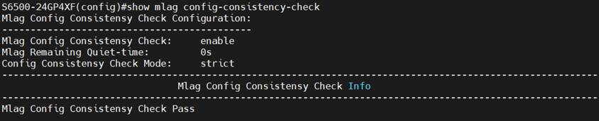
A1: As introduced, M-LAG peer devices will only synchronize table entries via the peer link; the configuration will not be automatically synced, so we must manually perform the same configuration on both M-LAG peer devices. When the configuration related to M-LAG differs on both sides, warnings will be printed. In this situation, use the command “show mlag config-consistency-check” to display all inconsistent configurations between the M-LAG peer devices. If all configurations are the same, the result of the consistency check will be displayed as passed.
Please note that the command “mlag config-consistency-check mode strict/loose” sets the M-LAG configuration consistency check mode as “strict” or “loose”. If the mode is set to strict, after detecting inconsistencies in key M-LAG configurations, the M-LAG member ports will be automatically shut down to prevent chaos during forwarding. If the mode is set to loose, only warnings will be printed, and the M-LAG member ports will remain up.
Is this faq useful?
Your feedback helps improve this site.


TP-Link Community
Still need help? Search for answers, ask questions, and get help from TP-Link experts and other users around the world.