


Standard Troubleshooting for SFP modules and Media Converters
Contents
Troubleshooting Guidance per Scenarios
Troubleshooting guidance for SFP-to-SFP Scenario
Troubleshooting guidance for SFP-to-Media-Converter Scenario
Troubleshooting guidance for Media-converter-to-media-converterScenario
Introduction
The SFP/Media Converter is designed for easy use in optical fiber transmission. When the connection does not work as expected after we set it up according to the Installation Guide, we need to do some troubleshooting. The checking includes, but is not limited to, the following three aspects:
1. Basic checking: LED status; the suitable fiber/Ethernet cable; the wavelength and the mode (multi/single); the speed, etc.
2. Connection checking: the matching of the Rx & Tx; the red laser of the multi-mode devices.
3. Hardware switches: the mode (Auto/Manual) of the Media Converter;
Application Scenarios
With our TP-Link fiber products, we have the following three kinds of application scenarios:
1. SFP to SFP

2. SFP to Media Converter

3. Media Converter to Media Converter

Troubleshooting Guidance per Scenarios
Troubleshooting guidance for SFP-to-SFP Scenario
In application scenario 1, insert the suitable SFP modules into the SFP slots and connect them with the proper fiber; then, the connection should be established.
Q1: Why is the LED of the SFP slot not on after plugging in the SFP module?
The LED status will not change when only the SFP module is plugged in. The LED will only light up when all connections are properly established and functioning correctly.
Q2: How can I tell the RX & TX ports of the SFP module?
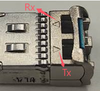
On the SFP module, you can see two triangles as noted in the picture below. The pole towards the outside means the Tx (Transmit) port, while the pole towards the inside means the Rx (Receive) port. When connecting the SFPs, ensure that the Tx and Rx ports are matched on both sides, specifically between the Tx port of module A and the Rx port of module B, and between the Rx port of module A and the Tx port of module B.
Q3: How can I determine if the SFP module is functioning correctly with the switch?
For multi-mode SFP module devices, since the wavelength of the multi-mode is in the range of visible light, we can see the red laser from the Tx port when we plug the SFP module into the SFP slot. When we plug the fiber, we can also see the red laser at the end of the fiber connected to the Tx port. However, for single-mode devices, we cannot observe this phenomenon because the wavelength of the single mode falls outside the visible light range.
Q4: What can I do if the LED is off after the connection?
1. For multi-mode SFP modules, we can check the red laser on both sides as we explained above; for single-mode SFP modules, you can check by using some professional Fiber-Optical Testers.
- If the Tx port of the SFP module does not emit a red laser when plugged into the SFP slot, the SFP module or the SFP slot may be defective. It is advised to change to another SFP module or another SFP slot to perform a test.
- If we can see the red laser from the Tx port of the SFP module, but there is no red laser from the end of the fiber that is connected to the Tx port, it may be the fault of the fiber; we can try another fiber.
2. For both multi-mode and single-mode SFP modules, we need to check the following points as well:
- Check if the Tx and Rx are matched as explained above.
- Verify that the size (9/125um, etc.), mode (single/multi), and length of the fiber meet the SFP module's requirements.
- Check if the speed of the SFP port matches the SFP module. For example, the Gigabit SFP module can only work with a 1000Mbps SFP port.
Troubleshooting guidance for SFP-to-media-converter Scenario
In application scenario 2, connect the Ethernet port to the switch’s port or other Ethernet devices with the Ethernet cable, and then connect the fiber port to the SFP module or other fiber devices with the proper fiber.
Q1: What can I do if the TP Link light is not on when the Ethernet port is connected?
When the Media Converter’s Ethernet port is connected, the TP Link light will go on, as shown in the picture below. Here we take MC210CS for example.
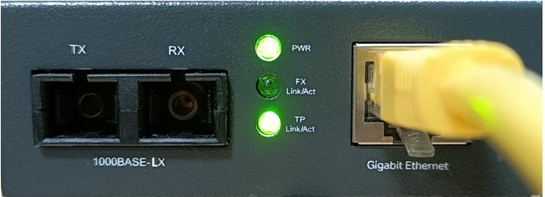
If the TP Link light is still off when the Ethernet port is connected, we need to check:
- If the speed of the Ethernet ports of the Media Converter and the device that it connects to match. For a Gigabit Ethernet Media Converter that only supports 1000BASE-T, it can only work with a 1000BASE-T Ethernet port; For other Gigabit Ethernet Media Converters that support 10/100/1000Base-TX, their ports support auto-negotiation, so they can work with 10/100/1000Base-TX for the port and negotiate the speed and duplex automatically. Similarly, the Fast Ethernet Media Converter's 10/100Base-TX port supports auto-negotiation, allowing it to work with a 10/100Base-TX port and negotiate the speed and duplex automatically.
- For the Fast Ethernet Media Converter, we need to make sure the LFP function is off. For more information about LFP, please refer to Q3.
- We should use Cat5 or above cable, and the length should not be longer than 100m.
- It is recommended to replace the cable or port for testing purposes.
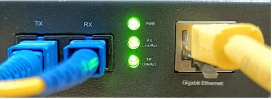
Q2: What can I do if the TP-Link FX Link light is not on after the fiber ports are connected?
After FX ports are also connected, the FX Link LED will go on as shown in the picture below, and the TP FX light will blink when there is data transmission. The troubleshooting in this part is the same as the application scenario 1, and you can refer to Q3 & Q4 in the application scenario 1 for help.
Troubleshooting guidance for Media-converter-to-media-converterScenario
For application scenario 3, the LED status and troubleshooting exhibit similar phenomena to those described above. For assistance, please refer to the steps outlined in application scenarios 1 and 2.
Note:
- For the Media Converter, we should power it on after the connection is set up.
- For an SFP module, such as TL-SM321A/B, that supports WDM (Wavelength Division Multiplex), they must work together.
- The TL-MC220L features a 1000BASE-T port and a 1000BASE-TX SFP port. The wavelength, transmission distance, and mode (single/multi) depend on the SFP module plugged into it.
Get to know more details of each function and configuration please go to Download Center to download the manual of your product.
QA
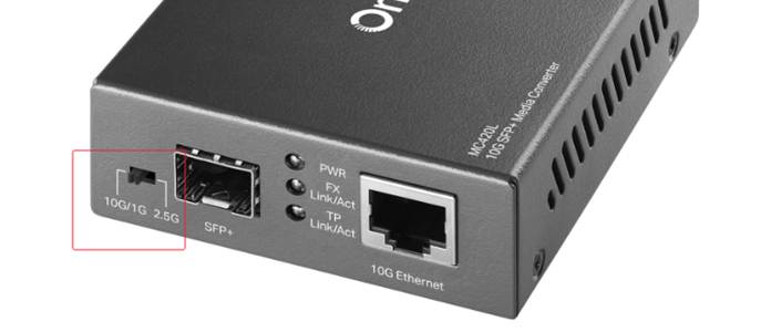
Q1: Is the media converter compatible with a 2.5G SFP module?
A1: MC420L v2.0 features a DIP switch for mode selection. Before inserting the SFP module, make sure you toggle the DIP switch to the 2.5G Mode. The 10G/1G Mode is enabled by default (switch toggled left). To activate the 2.5G Mode, toggle the switch to the right. In 2.5G mode, the media converter supports the IEEE 802.3bz and 2500Base-X protocols.
Q2: Can 10G SFP+ modules run at 1G?
A2: TP-Link 10G SFP+ modules are capable of running at 1 Gbps. When a 10G SFP+ module is running at 1 Gbps, make sure that the data rate of the SFP/SFP+ ports at both ends is configured to 1 Gbps.
Is this faq useful?
Your feedback helps improve this site.


TP-Link Community
Still need help? Search for answers, ask questions, and get help from TP-Link experts and other users around the world.