FAQ: Interface and Device Management
|
|
This guide applies to: T1500/T1500G/T1600G/T1700G/T1700X/T2500/T2500G/T2600G/T2700G/T3700G |

1What Mechanism Is Used in a Ring Stack System to Prevent Loops?
In a ring stack system, a certain cable is automatically blocked to prevent loops.
Counting from the stack port with the greater port number in the master switch, the cable numbered (n/2)+1 will be blocked. Here, n is the number of switches in the stack system. If n/2 is not an integer, then the n/2 will be rounded down to the nearest integer. If n=5, for example, then n/2 will be taken to be 2.
For example, a ring stack system consists of three switches.
Figure 1 A Ring Stack System
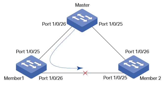
In this topology, n=3, so (n/2)+1=2. For the port number 1/0/26 is greater than port number 1/0/25, the 2nd cable from the stack port 1/0/26 of the master is blocked. That means the stack port 1/0/26 of slave 1 and the stack port 1/0/25 of slave 2 are blocked.
2What Will Happen if a Link Fails in the Stack System?
If it is a chain stack, the link failure will cause a stack split. The original stack will split into two new chain stacks.
If it is a ring stack, once the link has failed, the stack will become a chain stack and still continue to work normally.
3How Do I Use DDM to View the Transmitting and Receiving Power of the SFP Module?
DDM (Digital Diagnostic Monitoring) helps the user to monitor the status of the SFP modules inserted into the SFP ports on the switch. To use DDM, both of the switch and the SFP module should support DDM. At present, T2500G-28TC/T2600G-18TS series switches and T2600G-28TS 2.0 switch support DDM function.
You can view the transmitting and receiving power of the SFP module using command show ddm status.
Switch(config)#show ddm status
Temperature(C) Voltage(V) Bias Current(mA) TxPower(mW)
RxPower(mW) Data Ready Rx Los Tx Fault
Gi1/0/17 -- -- -- --
-- -- -- --
Gi1/0/18 45.492188 3.318900 19.072000 0.253200
0.352127 False False False
4How Do I View the Connection Status of the Ethernet Cable?
The switch supports Cable Test function to test the cable connection status, which allows you to easily locate and diagnose the trouble spot of the network. You can use the command show cable-diagnostics interface gigabitEhternet port to view the cable status.
Switch#show cable-diagnostics interface gigabitEhternet 1/0/2
Port Pair Status Length Error
Gi1/0/2 Pair-A Normal 2 (+/- 10m) ---
Pair-B Normal 2 (+/- 10m) ---
Pair-C Normal 0 (+/- 10m) ---
Pair-D Normal 2 (+/- 10m) ---
Status results include Normal, Close, Open and Crosstalk.
Normal: The cable works normally.
Close: A short circuit exists in the cable.
Open: No device is connected to the other end or the connectivity is broken.
Crosstalk: Impedance mismatch caused by poor cable quality.
Length: If the connection status is Normal, the length range of the cable is displayed here.
Error: If the connection status is Close, Open or Crosstalk, the error length range of the cable is displayed here.
5How Do I Use SNMP to View the CPU and Memory Utilization?
Monitoring CPU and Memory utilization is a common requirement in network management. TP-Link T1600G/T2600G series switches provide corresponding SNMP MIB objects for you to view the CPU and memory utilization.
The MIB object “tpSysMonitorCpu5Seconds” indicates the CPU utilization in 5 seconds, and its OID is 1.3.6.1.4.1.11863.6.4.1.1.1.1.2.
The MIB object “tpSysMonitorCpu1Minutes” indicates the CPU utilization in 1 minute, and its OID is 1.3.6.1.4.1.11863.6.4.1.1.1.1.3.
The MIB object “tpSysMonitorCpu5Minutes” indicates the CPU utilization in 5 minutes, and its OID is 1.3.6.1.4.1.11863.6.4.1.1.1.1.4.
The MIB object “tpSysMonitorMemoryUtilization” indicates the memory utilization, and its OID is 1.3.6.1.4.1.11863.6.4.1.2.1.1.2.
6What Is the Difference between Log Buffer and Log File?
Both Log Buffer and Log File can be used to record system logs, helping the network administrator to monitor the network status and to troubleshoot. However, there are some differences between them.
Log Buffer
Log Buffer is enabled by default, and automatically records the logs with specified severity levels. The logs recorded in Log Buffer will be lost after the switch reboots.
Log File
Log File is disabled by default. After the Log File is enabled, the logs with the specified severity will be synchronized to the Log File. The logs recorded in the Log File will not be lost after the switch reboots and can be exported to your management host.
7Are All the Logs Recorded in the Log Buffer?
Not all the logs are recorded in the Log Buffer.
By default, only the logs with a severity level equal to or less than 6 are recorded in the Log Buffer.
Users can also specify the severity level of logs that need to be recorded to Log buffer by running the command logging buffer level level.
The storage space of the Log Buffer is limited; at most 1024 logs can be recorded. When the number of logs reaches the limit, the new log will replace the earliest recorded log.
8How Do I Back up the Log File?
You can export the log file to your management host. If the switch breaks down, you can check the log file for troubleshooting:
1)Enable Log File and specify the severity level of the logs to be recorded. By default, the logs will be synchronized to the Log File every 24 hours. If necessary, you can modify the synchronization frequency by running the command logging file flash frequency {periodic periodic | immediate}.
2)Log File can only be exported on the web page. You can export the Log File to your management host on the Maintenance > Log > Backup Log page. The logs will be saved as a .cfg file, and you can open this file with Notepad.
9How Do I Enable PoE Function?
PoE (Power over Ethernet) function is enabled on PoE ports by default. These ports can supply power to connected PDs (Power Device) over the Ethernet cable.
You can also specify a time range for each PoE port, then the port will supply power only during the time range.
10What Can I Do if Two Connected RJ45 Ports Cannot be Up?
1)Make sure that the Ethernet cable is normal and is plugged in securely at both ends.
2)Make sure that both of the ports are enabled.
3)Make sure that the speed and duplex mode of both ports are the same.
4)Check to verify if there exists Combo ports. If so, make sure that the associated SFP port is not working. The SFP port and the associated RJ45 port cannot be used simultaneously. If so, only the SFP port works.
5)If the problem still persists, please contact support@tp-link.com.
11What Can I Do if Two Connected SFP Ports Cannot be Up?
1)Make sure that the fiber is normal, and firmly plugged.
2)Make sure that both of the ports are enabled.
3)Make sure that the speed and duplex mode of both ports are the same.
4)Make sure that the SFP module is compatible with the switch, and the two SFP modules at both ends can work together.
5)Make sure that the fiber matches the SFP module. Single-mode fiber works with single-mode module, and multi-mode fiber works with multiple-mode module.
6)If the problem still persists, please contact support@tp-link.com.
12How Do I Identify A Combo Port?
You can identify the Combo port on the front panel. A Combo port consists of one RJ45 port and one SFP port, and they share the same port ID. If two ports have the same port ID and one of them is a RJ45 port while the other one is a SFP port, they can be identified as a Combo port.
You can also check the Installation Guide of the switch if you are unsure which port is the Combo port.
A Combo port consists of one RJ45 port and one SFP port. The SFP port and the associated RJ45 port cannot work simultaneously. If both of the two ports are connected, only the SFP port works.
14What Principles Should be Followed When Choosing the Speed and Duplex Mode?
Generally, it is recommended to configure both devices of a link to work in Auto-Negotiation mode or manually configure them to work in the same speed and duplex mode.
Auto-Negotiation enables two devices at both ends of a link to advertise their speed and duplex abilities to each other, and negotiate the optimal speed and duplex mode.
If the local device works in Auto-Negotiation mode while the peer device does not, the local device will automatically detect and match the speed with the peer device. The local device will work in half-duplex mode, no matter what duplex mode the peer device is in. So the duplex mode of the two devices will be different, which may cause some problems like packet loss and packet conflict.
15Can the Switch Forward the PAUSE Frame?
No.
In a full-duplex link, with Flow Control enabled, when a device gets overloaded it will send a PAUSE frame to notify the peer device to stop sending data for a specified period of time. The destination MAC address of the PAUSE frame is a reserved multicast address 01-80-C2-00-00-01, and switches will not forward frames with this destination address according to IEEE 802.3. So the PAUSE frame won’t be forwarded.
16What Is the MTU of an Ethernet Port?
MTU (Maximum Transmission Unit) is the size of the largest frame that can be transmitted and forwarded by the port.
For TP-Link switches, the default MTU size is 1518 bytes. If you want the interface to support jumbo frames, please use the command jumbo to enable Jumbo function. When Jumbo function is enabled, the MTU size is 9216 bytes.
|
|
Note: For T1500-28TC/T1500-28PCT/T2600G-18TS switch, the MTU size of jumbo frame can be manually set according to your needs. You can use command jumbo-size size to specify the size. The MTU size ranges from 1518 to 9216 bytes, and the default is 1518 bytes. |

17How Do I Assign an IP Address to a Physical Port ?
By default, the physical ports of the switch are layer 2 ports, and do not have IP addresses.
To assign an IP address to a physical port, you can configure the port to be a VLAN interface or a routed port. VLAN interfaces and routed ports are logical layer 3 interfaces, which have their own IP addresses and subnet masks. They work as the gateway of the subnet to forward layer 3 packets.
Configure the VLAN interface
Add the port to a VLAN, then create the corresponding VLAN interface. You can configure an IP address for the VLAN interface.
For example, you can add port 1/0/2 to VLAN 2, and assignan IP address 192.168.1.100 and a subnet mask of 255.255.255.0 VLAN interface 2 .
Switch(config)#vlan 2
Switch(config-vlan)#exit
Switch(config)#interface gigabitEthernet 1/0/2
Switch(config-if)#switchport trunk allowed vlan 2
Switch(config-if)#exit
Switch(config)#interface vlan 2
Switch(config-if)#ip address 192.168.1.100 255.255.255.0
Switch(config-if)#exit
Configure the routed port
Switch the physical port to a layer 3 routed port, allowing you to assign an IP address to it.
For example, you can switch port 1/0/3 to a routed port then assign it an IP address of 192.168.0.100 and a subnet mask of 255.255.255.0.
Switch(config)#interface gigabitEthernet 1/0/3
Switch(config-if)#no switchport
Switch(config-if)#ip address 192.168.0.100 255.255.255.0
Switch(config-if)#exit
18How Do I Use Port Isolation to Limit A Port’s Communication to Only Specific Ports on the Same Switch?
Port Isolation is used to limit the data transmitted by a port. The port can only send packets to ports specified in its forward list.
If you want to restrict a port only communicate with specific ports, you can configure a forward list for a port to restrict it to communicate only with the ports you specify.
|
|
Note: Since communications are bidirectional, if you want two ports communicate normally, they need to be in each other’s forward lists. |
For example, if you want port 1/0/1 to only communicate with port 1/0/2, you can set port 1/0/2 as the only forwarding port for port 1/0/1, and set port 1/0/1 as the only forwarding port for port 1/0/2.
Switch#configure
Switch(config)#interface gigabitEthernet 1/0/1
Switch(config-if)#port isolation gi-forward-list 1/0/2
Switch(config-if)#exit
Switch(config)#interface gigabitEthernet 1/0/2
Switch(config-if)#port isolaion gi-forward-list 1/0/1
Switch(config-if)#exit