Monitoring the Network (CPE and WBS)
CHAPTERS
1. View the Device Information
3. View Wireless Signal Quality
|
|
This guide applies to: CPE610(UN) 1.0, CPE520(UN) 3.0, CPE510(UN) 3.0, CPE210(UN) 3.0, CPE210(EU) 3.0, CPE220(UN) 3.0, CPE510(UN) 1.0, CPE510(UN) 2.0, CPE210(UN) 1.0, CPE210(UN) 2.0, CPE220(UN) 1.0, CPE220(UN) 2.0, CPE520(UN) 1.0, CPE520(UN) 2.0, WBS210(UN) 1.0, WBS210(UN) 2.0, WBS510(UN) 1.0, WBS510(UN) 2.0. |

This guide introduces how to monitor the wireless network using the CPE/WBS products:
1. View the Device Information
2. View the Wireless Settings
3. View Wireless Signal Quality
4. View Radio Status
5. View the LAN Settings
6. View the WAN Settings
7. Monitor Throughput
8. Monitor Stations
9. Monitor Interfaces
10. Monitor ARP Table
11. Monitor Routes
12. Monitor DHCP Clients
13. Monitor Dynamic WAN
The following parts detailedly introduces these features.
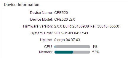
Go to the STATUS page. In the Device Information section, you can view the basic information of the device. To configure the device information, refer to Configuring the System.
Figure 1-1 Device Information
|
Device Name |
Displays the name of the device. By default, it is the product model. |
|
Device Model |
Displays the product model and the hardware version of the device. |
|
Firmware Version |
Displays the current firmware version of the device. |
|
System Time |
Displays the current system time. |
|
Uptime |
Displays the running time of the device. |
|
CPU |
Displays the CPU occupancy. |
|
Memory |
Displays the memory occupancy. |
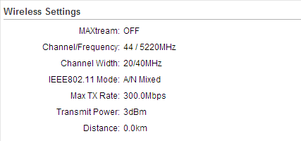
Go to the STATUS page. In the Wireless Settings section, you can view the parameters of the wireless network created by the device. To configure the parameters, refer to Configuring the Wireless Parameters.
Figure 2-1 Wireless Settings
|
MAXtream |
Displays the status of the MAXtream function. This function is only available in Access Point mode and AP Router mode. MAXtream is a TP-Link proprietary technology. It is based on TDMA (Time Division Multiple Access) so that data streams are transmitted in their own time slots. MAXtream aims to maximize throughput and minimize latency. “Hidden nodes” problem can also be eliminated with MAXtream enabled. MAXtream Technology is only compatible with Pharos series products. Working with products from other manufacturer will cause network fault. |
|
Channel/Frequency |
Displays the channel and frequency which are currently used by the device. |
|
Channel Width |
Displays the channel width which is currently used by the device. |
|
IEEE802.11 Mode |
Displays the IEEE802.11 protocol currently used by the device. |
|
Max TX Rate |
Displays the maximum data rate of the device during the sending of the wireless packets. |
|
Transmit Power |
Displays the transmit power which is currently used by the device. |
|
Distance |
Displays the wireless coverage distance. In the coverage of the device, the clients can be placed to get good wireless performance. |
Go to the STATUS page. In the Wireless Signal Quality section, you can view the current signal quality of the upstream wireless network. It is only applicable for the Client, Repeater (Range Extender), Bridge and AP Client Router (WISP Client) modes.
Figure 3-1 Wireless Signal Quality

|
Signal Strength (Horizontal/Vertical) |
Displays the received wireless signal strength of the root AP. |
|
Noise Strength |
Displays the received environmental noise from wireless interference on the operating frequency. |
|
SNR |
Displays the Signal to Noise Ratio (SNR) of the device. SNR refers to the power ratio between the received wireless signal strength and the environmental noise strength. The larger SNR value is, the better network performance the device can provide. |
|
Transmit CCQ |
Displays the wireless Client Connection Quality (CCQ). CCQ refers to the ratio of effective transmission bandwidth and the actual total bandwidth. It reflects the quality of the actual link. A larger value means a better utilization of the bandwidth. |
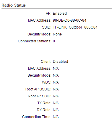
Go to the STATUS page. In the Radio Status section, you can view the radio status of the device.
Figure 4-1 Radio Status
|
AP |
Displays the status of the wireless AP function. With this enabled, the device can provide a wireless network for the clients. By default, it is enabled in Access Point, Repeater, Bridge, AP Router and AP Client Router modes and disabled in Client mode. |
|
MAC Address |
Displays the MAC address of the wireless interface connected to the clients. |
|
SSID |
Displays the wireless network name (SSID) created by the device. |
|
Security Mode |
Displays the security mode you’ve selected for your wireless network. There are three security modes: WPA-PSK, WPA and WEP. None means that no security mode is selected and all the hosts are allowed to access the wireless network directly. |
|
Connected Stations |
Displays the number of the connected stations. |
|
Client |
Displays the status of the wireless client function. With this function enabled, the device can connect to the root AP through wireless connection. By default, it is enabled in Client, Repeater, Bridge and AP Client Router modes and disabled in Access Point and AP Router modes. |
|
MAC Address |
Displays the MAC address of the wireless interface connected to the root AP. |
|
Security Mode |
Displays the security mode you’ve selected for your wireless network. There are three security modes: WPA-PSK, WPA and WEP. The security mode which is set on the device should be the same as that on the root AP. |
|
WDS |
Displays the status of the WDS (Wireless Distribution System) function. WDS is a communication system among multiple wireless networks . It is established between APs through wireless connection. WDS is used during the connection process between the device and the root AP. Enable: Forward data frames using four address fields. Disable: Forward data frames using three address fields. Auto: The device automatically negotiates the wireless data frame structure (three or four address fields) with the root AP. The selection of Auto is recommended. |
|
Root AP BSSID |
Displays the BSSID (Basic Service Set ID) of the root AP. BSSID is used to identify a BSS. Each BSS has its own BSSID. The BSSID is decided by the manufacturers, and it is usually related to the device’s MAC address. |
|
Root AP SSID |
Displays the wireless network name of the root AP. |
|
TX Rate |
Displays the data rate of the device during the sending of the wireless packets. |
|
RX Rate |
Displays the data rate of the device during the receiving of the wireless packets. |
|
Connection Time |
Displays the amount of time the device has been connected to the root AP. |
Go to the STATUS page. In the LAN section, you can view the LAN information of the device. To configure the LAN settings, refer to Configuring the Network.
Figure 5-1 LAN Parameters

|
MAC Address |
Displays the LAN port MAC address of the device. |
|
IP Address |
Displays the LAN port IP address of the device. |
|
Subnet Mask |
Displays the subnet mask of the LAN. |
|
Port |
Displays the current status of the LAN Ethernet port connections and the Maximum transmission rate of the plugged port. |
Go to the STATUS page. In the WAN section, you can view the WAN information of the device. To configure the LAN settings, refer to Configuring the Network.
Figure 6-1 WAN Parameters

|
Connection Type |
Displays the connection type of the device. |
|
MAC Address |
Displays the MAC address of the wireless interface connected to the root AP. |
|
IP Address |
Displays the IP address of the wireless interface connected to the root AP. |
|
Subnet Mask |
Displays the subnet mask of the wireless interface connected to the root AP. |
|
Default Gateway |
Displays the default gateway. |
|
DNS Server |
Displays the DNS server. |
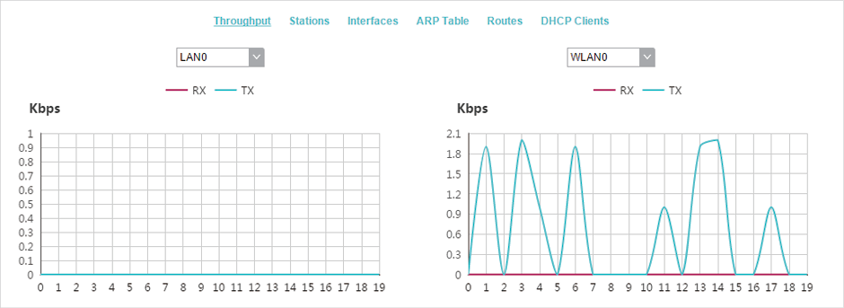
Go to the STATUS page. In the Monitor section, select Throughput and you can monitor the current data traffic of specified interfaces including LAN, WAN and BRIDGE.
Figure 7-1 Throughput
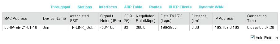
Go to the STATUS page. In the Monitor section, select Stations and you can monitor the information of all the stations that are connected to the device.
Figure 8-1 Stations
|
MAC Address |
Displays the MAC address of the station. |
|
Device Name |
Displays the device name of the station. |
|
Associated SSID |
Displays the SSID that the station is connected to. |
|
Signal/Noise (dBm) |
Displays the signal strength and the noise strength of the wireless network. The values of Chain0 and Chain1 can be displayed separately and can be displayed unitedly. |
|
CCQ (%) |
Displays the wireless Client Connection Quality (CCQ). CCQ refers to the ratio of effective transmission bandwidth and the actual total bandwidth. It reflects the quality of the actual link. A larger value means a better utilization of the bandwidth. |
|
Negotiate Rate (Mbps) |
Displays the station’s data rates of the last transmitted packets. |
|
Data TX/RX (kbps) |
Displays the station’s average data rates of the transmitted and received packets over the connection time. |
|
Distance (km) |
Displays the distance between the device and the station. |
|
IP Address |
Displays the IP address of the station. |
|
Connection Time |
Displays the connection duration. |
|
Auto Refresh |
Enable or disable Auto Refresh. With this feature enabled, the table will refresh automatically. |
Go to the STATUS page. In the Monitor section, select Interfaces and you can monitor the relevant information of the interfaces.
Figure 9-1 Interfaces

|
Interface |
Displays the interface of the device. |
|
MAC |
Displays the MAC address of the interface. |
|
IP Address |
Displays the IP address of the interface. |
|
MTU |
Displays the Maximum Transmission Unit (MTU) of the interface. It is the maximum packet size (in bytes) that the interface can transmit. |
|
RX packets |
Displays the total amount of packets received by the interface after the device is powered on. |
|
RX Bytes |
Displays the total amount of data (in bytes) received by the interface after the device is powered on. |
|
TX packets |
Displays the total amount of packets sent by the interface after the device is powered on. |
|
TX Bytes |
Displays the total amount of data (in bytes) sent by the interface after the device is powered on. |
|
Auto Refresh |
Enable or disable Auto Refresh. With this feature enabled, the table will refresh automatically. |
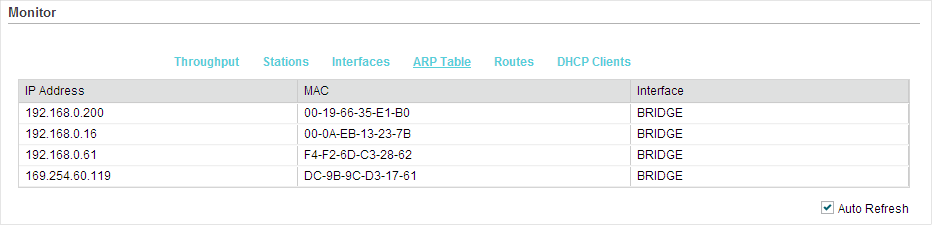
Go to the STATUS page. In the Monitor section, select ARP Table and you can monitor the ARP (Address Resolution Protocol) information recorded by the device.
ARP is used to associate each IP address to the unique hardware MAC address of each device on the network.
Figure 10-1 ARP Table
|
IP Address |
Displays the IP address of the corresponding ARP entry. |
|
MAC |
Displays the MAC address of the corresponding ARP entry. |
|
Interface |
Displays the interface connected to the device. |
|
Auto Refresh |
Enable or disable Auto Refresh. With this feature enabled, the table will refresh automatically. |
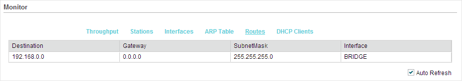
Go to the STATUS page. In the Monitor section, select Routes and you can monitor the routing entries recorded by the device.
Routing table is used for the device to decide the interface to forward the packets.
Figure 11-1 Routes
|
Destination |
Displays the IP address of the destination device or destination network. |
|
Gateway |
Displays the IP address of the appropriate gateway. |
|
SubnetMask |
Displays the Subnet Mask of the destination network. |
|
Interface |
Displays the interface that the destination device is on. |
|
Auto Refresh |
Enable or disable Auto Refresh. With this feature enabled, the table will refresh automatically. |
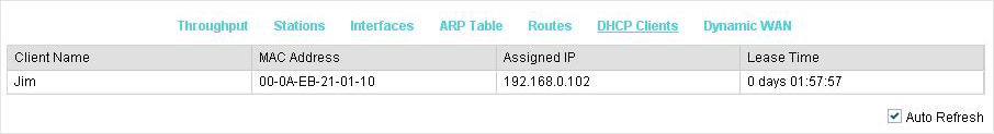
Go to the STATUS page. In the Monitor section, select DHCP Clients and you can monitor the information of all the DHCP clients.
Table 12-1DHCP Clients
|
Client Name |
Displays the device name of the client. |
|
MAC Address |
Displays the MAC address of the client. |
|
Assigned IP |
Displays the IP address that the device assigned to the client. |
|
Lease Time |
Displays the time that the client leased. When the time expires, the clients will request to renew the lease automatically. |
|
Auto Refresh |
Enable or disable Auto Refresh. With this feature enabled, the table will refresh automatically. |
|
|
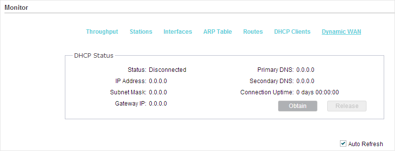
Tips Dynamic WAN submenu is only available in AP Router mode and AP client Router (WISP client) mode when the WAN connection type is PPPoE, PPTP, L2TP or Dynamic. |

Go to the STATUS page. In the Monitor section, select Dynamic WAN and you can monitor the WAN connection status of the device.
Figure 13-1 Dynamic WAN
|
Status |
Displays the status of the WAN connection. |
|
IP Address |
Displays the IP address of the WAN. |
|
Subnet Mask |
Displays the subnet mask of the WAN. |
|
Gateway IP |
Displays the gateway address of the device. |
|
Primary DNS |
Displays the primary DNS of the device. |
|
Secondary DNS |
Displays the secondary DNS of the device. |
|
Connection UPtime |
Displays the time that the latest WAN connection lasts. |
|
Obtain |
Click Obtain to obtain the WAN IP address from the upstream device. |
|
Release |
Click Release to release the WAN IP address. |
|
Auto Refresh |
Enable or disable Auto Refresh. With this feature enabled, the table will refresh automatically. |