Managing the Device (CPE and WBS)
CHAPTERS
2. Specify the Miscellaneous Parameters
8. Configure RSSI LED Thresholds
|
|
This guide applies to: CPE610(UN) 1.0, CPE520(UN) 3.0, CPE510(UN) 3.0, CPE210(UN) 3.0, CPE210(EU) 3.0, CPE220(UN) 3.0, CPE510(UN) 1.0, CPE510(UN) 2.0, CPE210(UN) 1.0, CPE210(UN) 2.0, CPE220(UN) 1.0, CPE220(UN) 2.0, CPE520(UN) 1.0, CPE520(UN) 2.0, WBS210(UN) 1.0, WBS210(UN) 2.0, WBS510(UN) 1.0, WBS510(UN) 2.0. |

This guide introduces how to manage CPE/WBS products:
1. Manage System Logs
2. Specify the Miscellaneous Parameters
3. Configure Ping Watch Dog
4. Configure Dynamic DNS
5. Configure Web Server
6. Configure SNMP Agent
7. Configure SSH Server
8. Configure RSSI LED Thresholds
The following parts detailedly introduces these features.
System logs record the events and activities while the device is running. If a failure happens on the router, System logs can help to diagnose the issue.
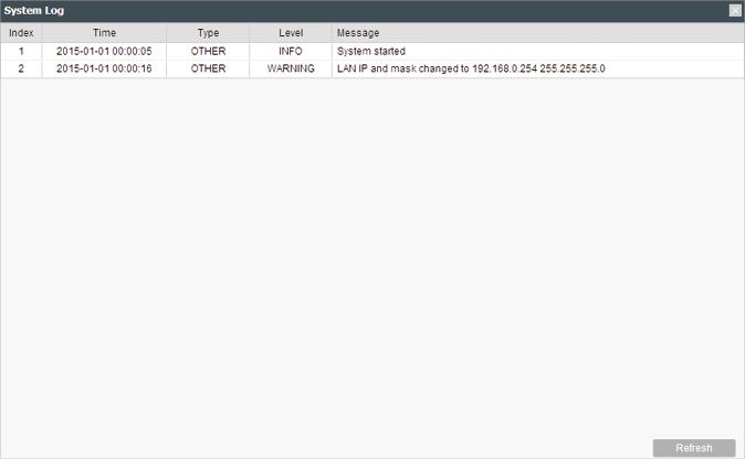
1)Go to the Management page. In the System Log section, you can perform the following operations.
Figure 1-1 Managing System Logs

|
Open System Log |
Click the Open button to view the system log.
This page displays detailed system logs that can be sorted on columns by ascending or descending order. Columns can be chosen from Time, Type, Level, and Message. |
|
Download to PC |
Click the Download button to download the system logs to your PC. |
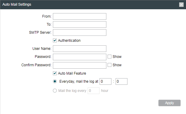
2)Click the Setting button to specify the Auto Mail Settings.
Figure 1-2 Specifying Auto Mail Settings
|
From |
Enter the sender’s E-mail address. |
|
To |
Enter the receiver’s E-mail address. |
|
SMTP Server |
Enter the IP address of the sender’s SMTP server. |
|
Authentication |
Enable or disable the authentication function. If the sender’s mailbox is configured. You can check the box to enable mail server authentication. Enter the sender’s username and password. |
|
Auto Mail Feature |
Enable or disable Auto Mail Feature. With this feature enabled, you can specify the way for the device to send the system log. |
2Specify the Miscellaneous Parameters
This section is used to specify miscellaneous parameters.
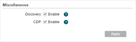
1)Go to the Management Page. In the Miscellaneous section, configure the following features and click Apply.
Figure 2-1 Specifying the Miscellaneous Parameters
|
Discovery |
Enable or disable Discovery. With this feature enabled, TP-Link Pharos Control software can discover the device. Pharos Control is a network management software developed independently by TP-Link and it currently supports Pharos series products. It can centralize monitoring and managing network devices in the network platform |
|
CDP |
Enable or disable CDP. With this function enabled, this device can share its information with the neighboring devices that support CDP (Cisco Discovery Protocol, a device discovery protocol developed by Cisco). |
2)Click Save.
Ping Watch Dog sets the device to continuously ping a user-defined IP address (it can be the internet gateway, for example) to check the network connectivity. If there is a connection failure then the device will automatically reboot.
Ping Watch Dog is dedicated to continuously monitoring the connectivity to a specific host using the Ping tool. The Ping tool sends ICMP echo request packets to the target host and listens for ICMP echo response. If the defined number of replies is not received, the tool reboots the device.
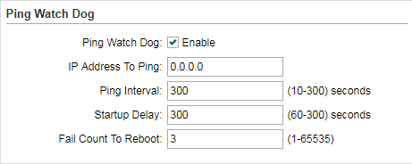
1)Go to the Management Page. In the Ping Watch Dog section, Enable this feature and configure the following features. Click Apply.
Figure 3-1 Configuring Ping Watch Dog
|
Ping Watch Dog |
Enable or disable Ping Watch Dog. |
|
IP Address To Ping |
Specify the IP address of the target host to which the device will send ping packets. |
|
Ping Interval |
Enter the time interval between two ping packets. The default value is 300 seconds. |
|
Startup Delay |
Enter the initial time delay from device startup to the first ICMP echo requests sent by Ping Watch Dog. The default value is 300 seconds. The Startup Delay value should be at least 60 seconds taking the device‘s initialization time in account. |
|
Fail Count To Reboot |
Enter the fail count of ICMP echo request. If the device sends the specified count of ICMP echo requests to the host and none of the corresponding ICMP echo response packets is received, Ping Watch Dog will reboot the device. The default value is 3. |
2)Click Save.
|
|
Note: The Dynamic DNS function is only available in AP router and AP Client router (WISP Client) mode. |

The main function of Dynamic DNS (DDNS) is mapping the fixed domain name to dynamic IP address.
When a device connects to the internet through PPPoE or Dynamic IP, the WAN IP address it gets is not fixed, which is inconvenient for the internet users to access the servers in the local area network through IP address. With Dynamic DNS function enabled, users can access servers using a fixed domain name.
The DDNS server will establish a mapping table about the dynamic IP address and the fixed domain name. When the WAN IP address of the device changes, it will make an update request to the specified DDNS server, and then the DDNS server will update the mapping relation between the IP address and the domain name. Therefore, whenever the WAN IP address changes, users on the internet can still access the servers in the local area network using a fixed, easy-to-remember domain name.
The DDNS function that serves as the client of DDNS service must work with DDNS server. Please register an account to DDNS service provider (NO-IP, Dyndns or Comexe) first.
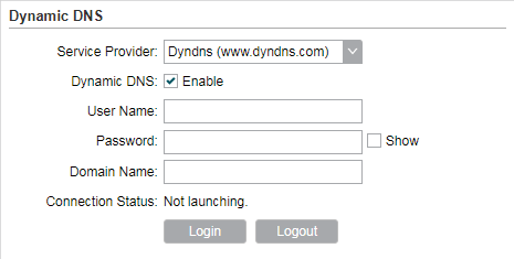
1)Go to the Management page. In the Dynamic DNS section, configure the following parameters and click Login.
Figure 4-1 Configuring Dynamic DNS
|
Service Provider |
Select the service provider. |
|
Dynamic DNS |
Enable or disable the Dynamic DNS feature. |
|
User Name |
Enter the user name of your DDNS account. |
|
Password |
Enter the password of your DDNS account. |
|
Domain Name |
Specify the domain name that you registered with your DDNS service provider. |
|
Connection Status |
Displays the connection status of the DDNS service. |
2)Click Apply, then click Save.
This function is used to configure the related parameters of Web server. Users can log in to the web management page to manage this device remotely over the internet through Web Server.
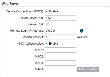
1)Go to the Management page. In the Web Server section, configure the following parameters and click Apply.
Figure 5-1 Configuring Web Server
|
Secure Connection (HTTPS) |
Enable or disable the HTTPS feature. HTTPS function is based on the SSL or TLS protocol working in transport layer. It supports a security access via a web browser. |
|
Secure Server Port |
Specify the server port number used in HTTPS. The default value is 443. |
|
Server Port |
Specify the server port number used in HTTP. The default value is 80. |
|
Remote Login IP Address |
Specify the IP address of the remote host. With this configured, the remote device can access the management interface remotely. |
|
Session Timeout |
Specify the session timeout time. The system will automatically release the connection when the time is up. |
|
MAC Authentication |
Enable or disable MAC Authentication. When it is enabled, you can specify up to four MAC address for authentication. With this function enabled, only the device whose MAC address is in the MAC list can access the management interface to configure the device. You can click Add PC’s MAC to quickly add your PC’s MAC address to the MAC list. |
2)Click Apply, then click Save.
You can get the traffic information and transmit condition by using the SNMP Agent function.
Simple Network Management Protocol (SNMP) is an application layer protocol that facilitates the exchange of management information between network devices. Main functions of SNMP include monitoring network performance, detecting and analyzing network error, configuring network devices, and so on. When the network working normally, SNMP can monitor the statistics, configuration. When networks have troubles, SNMP can detect and restore these troubles.
Configure the device as SNMP Agent, and it can receive and process the management message from the network management system.
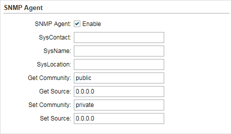
1)Go to the Management page. In the SNMP Agent section, configure the following parameters and click Apply.
Figure 6-1 Configuring SNMP Agent
|
SNMP Agent |
Enable or disable the SNMP Agent function. |
|
SysContaact |
Enter the textual identification of the contact person for this the device, for example, contact or e-mail address. |
|
SysName |
Enter a name for the device. |
|
Syslocation |
Enter the location of the device. For example, the name can be composed of the building, floor number, and room location. |
|
Get Community |
Specify the community that has read-only access to the device’s SNMP information. |
|
Get Source |
Enter the IP address that can serve as Get Community to read the SNMP information of this device. |
|
Set Community |
Specify the community who has the read and write right of the device’s SNMP information. |
|
Set Source |
Enter the IP address that can serve as Set Community to read and write the SNMP information of this device. |
2)Click Apply, then click Save.
|
|
Note: Defining community can allow management systems in the same community to communicate with the SNMP Agent. The community name can be seen as the shared password of the network hosts group. Thus, for the safety, we suggest modifying the default community name before enabling the SNMP Agent service. If the field of community is blank, the SNMP Agent will not respond to any community name. |
The SSH Server function is used for the users to log in and manage the device through SSH connection on the SSH client software.
SSH (Secure Shell) is a security protocol established on application and transport layers. SSH-encrypted-connection is similar to a telnet connection, but essentially the old telnet remote management method is not safe, because the password and data transmitted with plain-text can be easily intercepted. SSH can provide information security and powerful authentication when you log in this device remotely through an insecure network environment. It can encrypt all the transmission data and prevent the information in remote management from being leaked.
1)Go to the Management page. In the SSH Server section, configure the following parameters and click Apply.
Figure 7-1 Configuring SSH Server

|
Server Port |
Enter the TCP/IP port of the SSH Server. The default port is 22. |
|
SSH Login |
Enable or disable SSH function. |
|
Remote Management |
Enable or disable Remote Management. With this function enabled, TP-Link Pharos Control software can manage the device remotely. |
2)Click Save.
8Configure RSSI LED Thresholds
You can configure the LEDs on the device to light up when received signal levels reach the values defined in the following fields. This function can help a technician to easily deploy a Pharos series product without logging into the device (for example, for antenna alignment operation).
|
|
Note: CPE610 doesn’t support this feature. |
1)Go to the Management page. In the RSSI LED Thresholds section, configure the following parameters and click Apply.
Figure 8-1 Configuring RSSI LED Thresholds

|
LED1/LED2/LED3/LED4 |
Displays the LED number. |
|
Thresholds |
Specify the threshold for the desired LED. The specified LED will light up if the signal strength reaches the values in the field. The default values are set according to the verified optimum values. We recommend you keep it by default. The default LED threshold values may vary among different product models in terms of radio features. |
2)Click Apply, then click Save.