Managing EAP (Standalone EAP)
CHAPTERS
3. Configure Management Access
4. Configure Trunk (For EAP330)
6. Configure PoE (For EAP225-Wall)
|
|
This guide applies to: EAP225-Outdoor 1.0, EAP110-Outdoor 3.0, EAP110 4.0, EAP115 4.0, EAP115-Wall 1.0, EAP225-Wall 2.0, EAP225 3.0, EAP245 3.0, EAP320 2.0, EAP330 2.0. |

This guide introduces how to manage your EAP, including:
Manage System Logs
Configure Web Server
Configure Management Access
Configure Trunk (For EAP330)
Configure LED
Configure Wi-Fi Control (For EAP115-Wall)
Configure PoE (For EAP225-Wall)
Configure SSH
Configure Management VLAN
Configure SNMP
System logs record information about hardware, software as well as system issues and monitors system events. With the help of system log, you can get informed of system running status and detect the reasons for failure.
To manage system logs, go to the Management > System Log page.
Figure 1-1 System Log Page
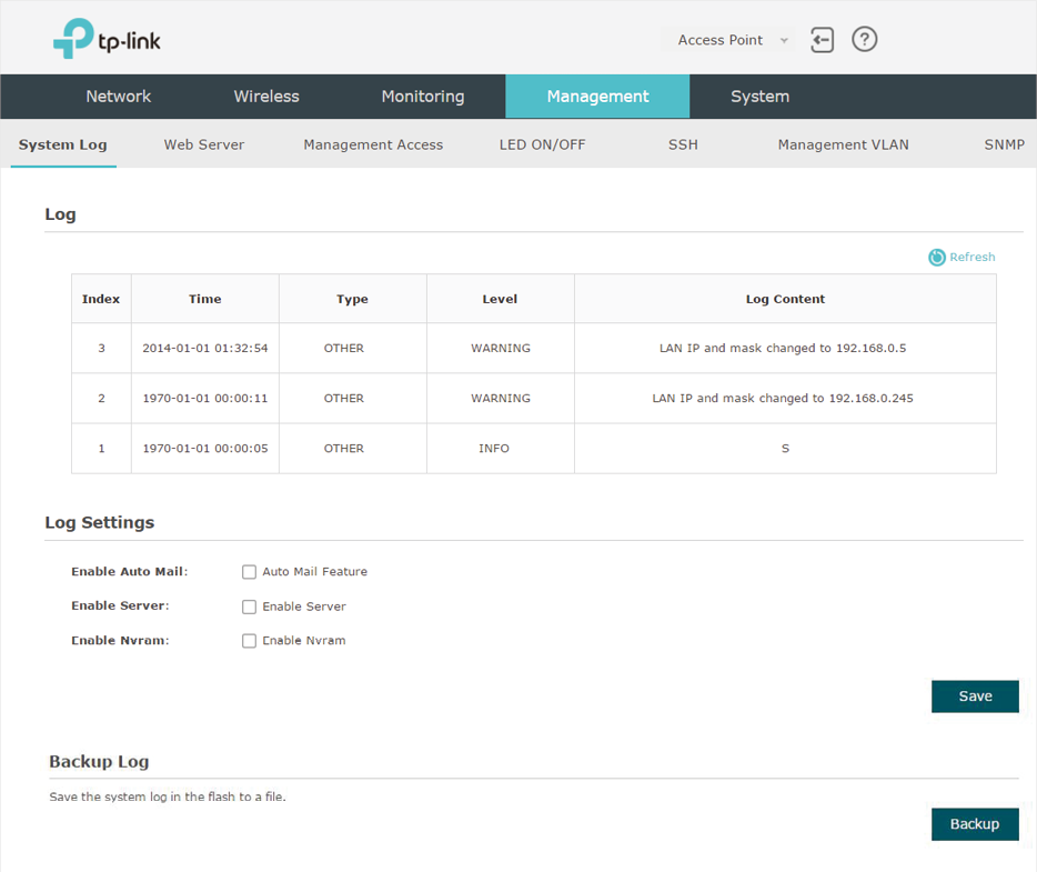
On this page, you can view the system logs and configure the way of receiving system logs. For EAP320/EAP330/EAP225, you can also backup the system logs to your local host.
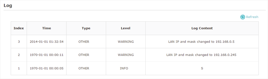
1.1View System Logs
In the Log section, you can click  to refresh the logs and view them in the table.
Figure 1-2 Viewing System Logs
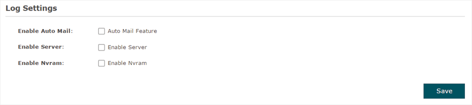
1.2Configure the Way of Receiving Logs
In the Log Settings section, you can configure the ways of receiving system logs.
Figure 1-3 Configuring the Way of Receiving Logs
Follow the steps below to configure this feature:
1)Check the corresponding box to enable one or more ways of receiving system logs, and configure the related parameters. Three ways are available: Auto Mail, Server and Nvram.
If Auto Mail is configured, system logs will be sent to a specified mailbox. Check the box to enable the feature and configure the related parameters.
|
|
Tips SSL encryption is not currently supported. |

Figure 1-4 Configuring Auto Mail
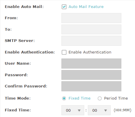
The following table introduces how to configure these parameters:
|
From |
Enter the sender’s E-mail address. |
|
To |
Enter the receiver’s E-mail address. |
|
SMTP Server |
Enter the IP address of the sender’s SMTP server. Note: At present, the domain name of SMTP server is not supported in this field. |
|
Enable Authentication |
If the sender’s mailbox is configured with You can check the box to enable mail server authentication. Enter the sender’s username and password. |
|
Time Mode |
Select Time Mode: Fixed Time or Period Time. Fixed Time means that the system logs will be sent at the specific time every day. Period Time means that the system logs will be sent at the specific time interval. |
|
Fixed Time |
If you select Fixed Time, specify a fixed time to send the system log mails. For example, 08:30 indicates that the mail will be sent at 8:30 am everyday. |
|
Period Time |
If you select Period Time, specify a period time to regularly send the system log mail. For example, 6 indicates that the mail will be sent every six hours. |
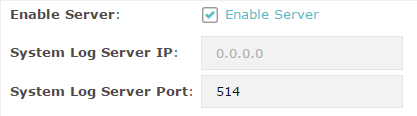
If Server is configured, system logs will be sent to the specified system log server, and you can use the syslog software to view the logs on the server.
Enable this feature and enter the IP address and port of the system log server.
Figure 1-5 Configuring Server
Nvram (Non-volatile Random Access Memory) is a RAM that can still save data even if a device is power off. With this option enabled, the Nvram feature can help reserve the system logs when the EAP is power off.
Figure 1-6 Configuring Nvram

2)Click Save.
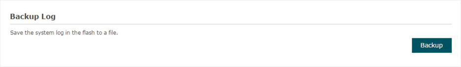
1.3Backup Logs (For EAP320/EAP330/EAP225)
In the Backup Log section, you can click  to backup the current system logs into a file and save the file on your local host.
Figure 1-7 Backuping Logs
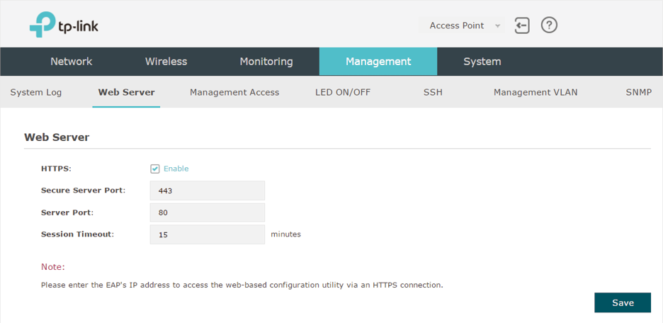
With the web server, you can log in to the management web page of the EAP. You can configure the web server parameters of the EAP according to your needs.
To configure Web Server, go to the Management > Web Server page.
Figure 2-1 Web Server Page
Follow the steps below to configure Web Server:
1)Refer to the following table to configure the parameters:
|
HTTPS |
HTTPS (Hypertext Transfer Protocol Secure) function is based on the SSL or TLS protocol. It provides a secure connection between the client and the EAP. HTTPS is enabled by default. |
|
Secure Server Port |
Designate a secure server port for web server in HTTPS mode. By default the port is 443. |
|
Server Port |
Designate a server port for web server in HTTP mode. By default the port is 80. |
|
Session Timeout |
Set the session timeout. If you do nothing with the web page within the timeout, the system will log out automatically. You can log in again if you want to go back to web page. |
2)Click Save.
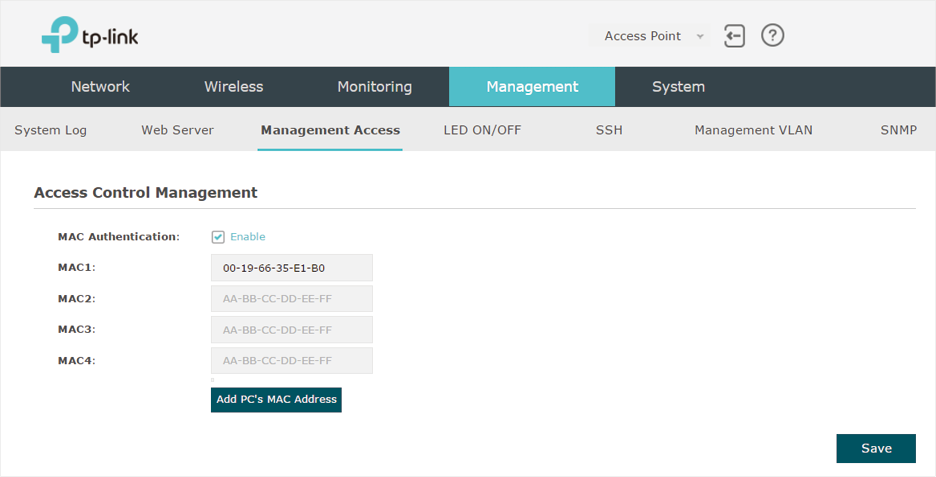
By default, all hosts in the LAN can log in to the management web page of the EAP with the correct username and password. To control the hosts’ access to the web page of the EAP, you can specify the MAC addresses of the hosts that are allowed to access the web page, and other hosts without MAC addresses specified are not allowed to access the web page.
To configure Management Access, go to the Management > Management Access page.
Figure 3-1 Management Access Page
Follow the steps below to configure Management Access on this page:
1)Check the box to enable MAC Authentication.
2)Specify one or more MAC addresses in the MAC1/MAC2/MAC3/MAC4 fields. Up to four MAC addresses can be added.
3)Click Save.
|
|
Tips •You can click •Verify the MAC addresses carefully. Once the settings are saved, only the hosts in the MAC address list can access the web page of the EAP. •If you cannot log in to the web page after saving the wrong configuration, you can reset the EAP to the factory defaults and use the default username and password (both admin) to log in. |
 to quickly add the MAC address of your current logged-in host, .
The trunk function can bundle multiple Ethernet links into a logical link to increase bandwidth and improve network reliability. The EAP330 has two 1000Mbps Ethernet ports. If the Trunk function is enabled and the ports are in the speed of 1000Mbps Full Duplex, the whole bandwidth of the trunk link is up to 4Gbps (2000Mbps * 2).
|
|
Tips The trunk feature here refers to static trunk. Make sure that the trunk mode of the peer is static. |
To configure Trunk, go to the Management > Trunk page.
Figure 4-1 Trunk Page
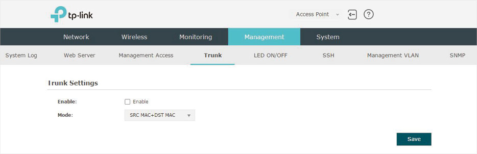
Follow the steps below to configure Trunk on this page:
1)Check the box to enable Trunk.
2)Select the trunk algorithm mode from the drop-down list. Three options are available: SRC MAC+DST MAC, DST MAC and SRC MAC. Based on the selected algorithm mode, the EAP determines which physical port is used to send out the received packet.
With SRC MAC+DST MAC selected, the EAP determines the outgoing port based on both the source and destination MAC addresses of the packet.
With DST MAC selected, the EAP determines the outgoing port baesed on the destination MAC address of the packet.
With SRC MAC selected, the EAP determines the outgoing port based on the source MAC address of the packet.
3)Click Save.
You can turn on or off the LED light of the EAP.
To configure LED, go to the Management > LED ON/OFF page.
Figure 5-1 LED ON/OFF Page
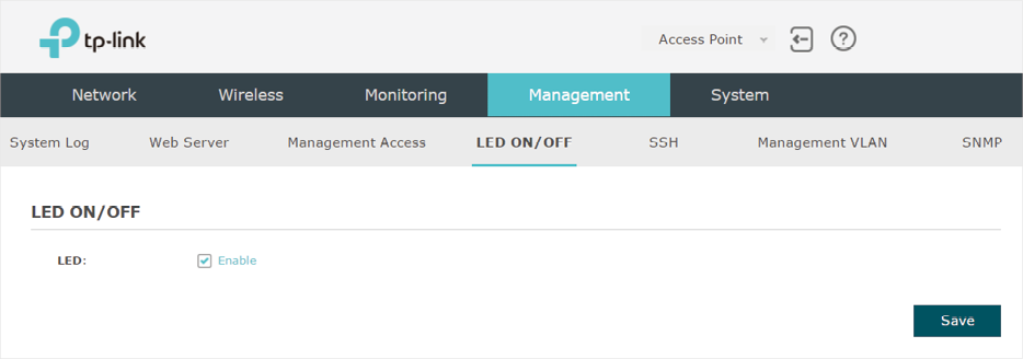
Check the box to turn on or turn off the LED light of the EAP, and click Save.
5.1Configure Wi-Fi Control (For EAP115-Wall)
EAP115-Wall has an LED/Wi-Fi button on the front panel. With Wi-Fi Control enabled, you can press the button to turn on or off both of the Wi-Fi and LED at the same time.
To configure Wi-Fi Control, go to the Management > Wi-Fi Control page.
Figure 5-2 Wi-Fi Control Page
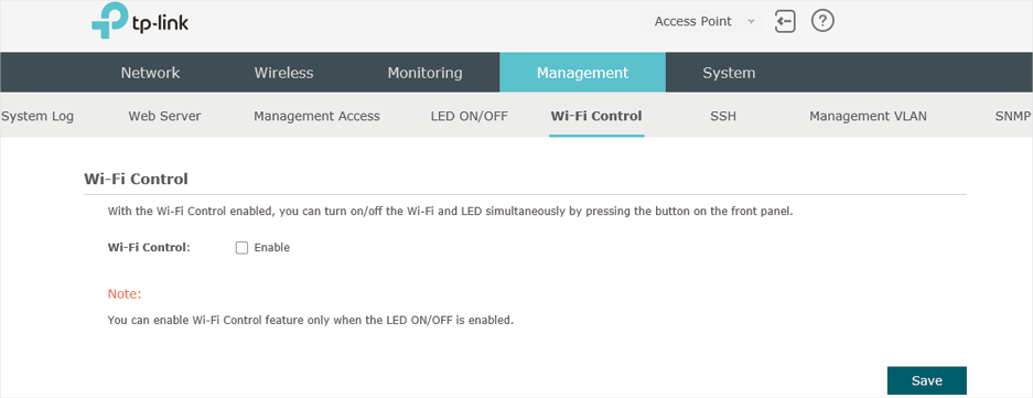
Check the box to enable Wi-Fi Control.
|
|
Tips You can enable Wi-Fi Control only when the option LED ON/OFF is enabled. |
6Configure PoE (For EAP225-Wall)
EAP225-Wall has a PoE out port that can transmit data and supply power to the client simultaneously. You can also disable the PoE feature to make the port transmit data only.
To configure PoE, go to the Management > PoE Out page.
Figure 6-1 PoE Out Page
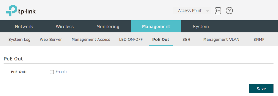
Check the box to enable the PoE feature.
If you want to remotely log in to the EAP via SSH, you can deploy an SSH server on your network and configure the SSH feature on the EAP.
To configure SSH, go to the Management > SSH page.
Figure 7-1 SSH Page
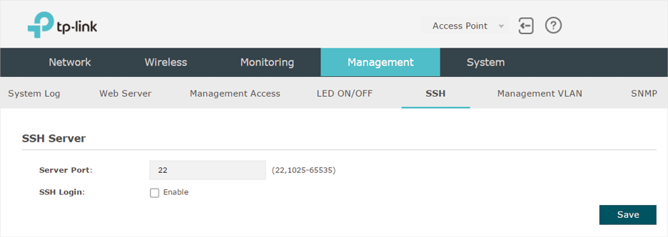
Follow the steps below to configure SSH on this page:
1)Enter the port number of the SSH server.
2)Check the box to enable SSH Login. By default, it is disabled.
3)Click Save.
Management VLAN provides a safer method to manage the EAP. With Management VLAN enabled, only the hosts in the Management VLAN can access the web page of the EAP. Since most hosts cannot process VLAN TAGs, you can connect the management host to the network via a switch, and set up correct VLAN settings for the switches on the network to ensure the communication between the host and the EAP in the Management VLAN.
To configure Management VLAN, go the Management > Management VLAN page.
Figure 8-1 Management VLAN Page
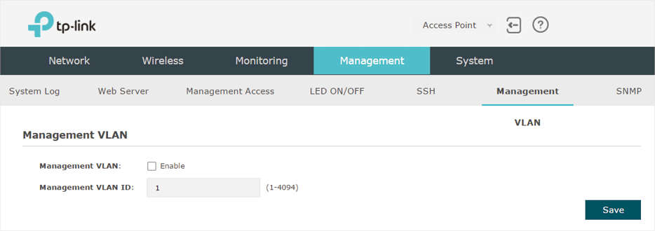
Follow the steps below to configure Management VLAN on this page:
1)Check the box to enable Management VLAN.
2)Specify the VLAN ID of the management VLAN. Only the hosts in the Management VLAN can log in to the EAP via the Ethernet port.
3)Click Save.
The EAP can be configured as an SNMP agent and work together with the SNMP manager. Once the EAP has become an SNMP agent, it is able to receive and process request messages from the SNMP manager. At present, the EAP supports SNMP v1 and v2c.
To configure the EAP as an SNMP agent, go to the Management > SNMP page.
Figure 9-1 SNMP Page
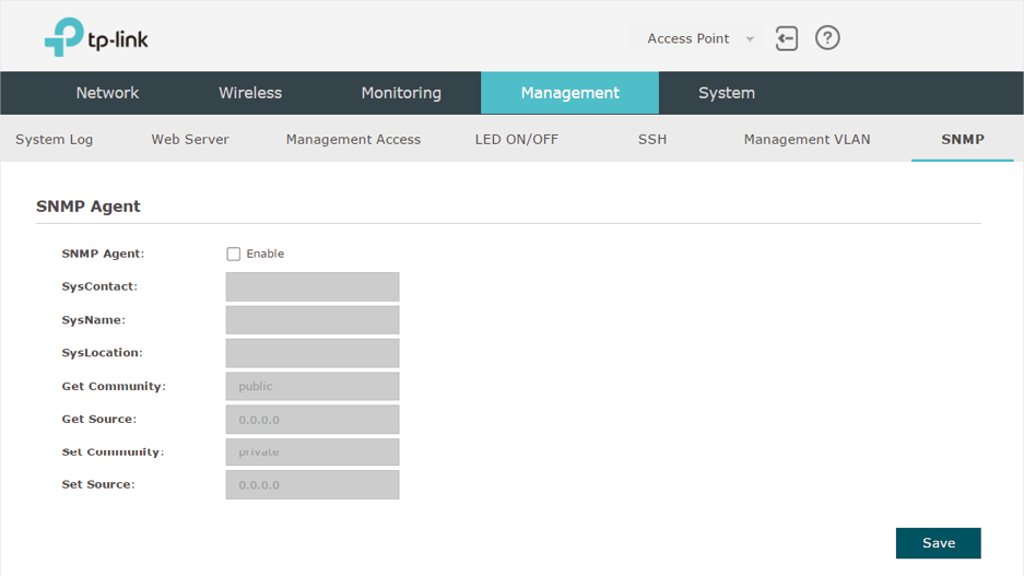
Follow the steps below to complete the configuration on this page:
1)Check the box to enable SNMP Agent.
2)Refer to the following table to configure the required parameters:
|
SysContact |
Enter the textual identification of the contact person for this managed node. |
|
SysName |
Enter an administratively-assigned name for this managed node. |
|
SysLocation |
Enter the physical location of this managed node. |
|
Get Community |
Community refers to a host group aiming at network management. Get Community only has the read-only right of the device’s SNMP information. The community name can be considered a group password. The default setting is public. |
|
Get Source |
Defines the IP address (for example, 10.10.10.1) for management systems that can serve as Get Community to read the SNMP information of this device. The default is 0.0.0.0, which means all hosts can read the SNMP information of this device. |
|
Set Community |
Set Community has the read and write right of the device’s SNMP information. Enter the community name that allows read/write access to the device’s SNMP information. The community name can be considered a group password. The default setting is private. |
|
Set Source |
Defines the IP address (for example, 10.10.10.1) for management systems that can serve as Set Community to read and write the SNMP information of this device. The default is 0.0.0.0, which means all hosts can read and write the SNMP information of this device. |
3)Click Save.
|
|
Tips Defining community can allow management systems in the same community to communicate with the SNMP Agent. The community name can be seen as the shared password of the network hosts group. Thus, for the security, we recommend that modify the default community name before enabling the SNMP Agent service. If the field of community is blank, the SNMP Agent will not respond to any community name. |