Diagnosing the Device & Network
CHAPTERS
3. Appendix: Default Parameters
|
|
This guide applies to: T1500G-8T v2 or above, T1500G-10PS v2 or above, T1500G-10MPS v2 or above, T1500-28PCT v3 or above, T1600G-18TS v2 or above, T1600G-28TS v3 or above, T1600G-28PS v3 or above, T1600G-52TS v3 or above, T1600G-52PS v3 or above, T1700X-16TS v3 or above, T1700G-28TQ v3 or above, T2500G-10TS v2 or above, T2600G-18TS v2 or above, T2600G-28TS v3 or above, T2600G-28MPS v3 or above, T2600G-28SQ v1 or above, T2600G-52TS v3 or above. |

The device diagnostics feature provides cable testing, which allows you to troubleshoot based on the connection status, cable length and fault location.
1.1Using the GUI
Choose the menu MAINTENANCE > Device Diagnostics to load the following page.
Figure 1-1 Diagnosing the Cable
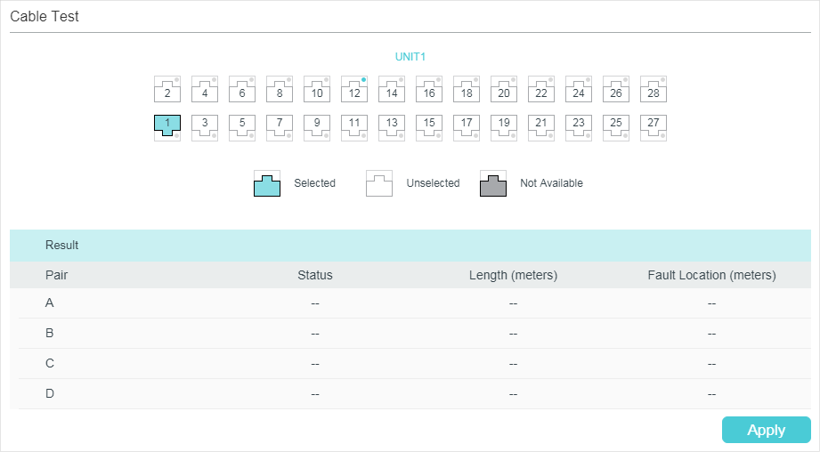
Follow these steps to diagnose the cable:
1)Select your desired port for the test and click Apply.
2)Check the test results in the Result section.
|
Pair |
Displays the Pair number. |
|
Status |
Displays the cable status. Test results include normal, closed, open and crosstalk. Normal : The cable is connected normally. Closed: A short circuit is being caused by abnormal contact of wires in the cable. Open: No device is connected to the other end or the connection is broken. Crosstalk: Impedance mismatch due to the poor quality of the cable. |
|
Length |
If the connection status is normal, the length range of the cable is displayed. |
|
Fault Location |
If the connection status is short, close or crosstalk, here displays the length from the port to the trouble spot. |
1.2Using the CLI
On privileged EXEC mode or any other configuration mode, you can use the following command to check the connection status of the cable that is connected to the switch.
|
show cable-diagnostics interface { fastEthernet port | gigabitEthernet port | ten-gigabitEthernet port } View the cable diagnostics of the connected Ethernet Port. port: Enter the port number in 1/0/1 format to check the result of the cable test. show cable-diagnostics careful interface { fastEthernet port | gigabitEthernet port | ten-gigabitEthernet port } View the cable diagnostics of the connected Ethernet Port. When taking the careful cable test, the switch will only test the cable for the port which is in the link-down status. port: Enter the port number in 1/0/1 format to check the result of the cable test. |
The following example shows how to check the cable diagnostics of port 1/0/2:
Switch#show cable-diagnostics interface gigabitEhternet 1/0/2
Port Pair Status Length Error
Gi1/0/2 Pair-A Normal 2 (+/- 10m) ---
Pair-B Normal 2 (+/- 10m) ---
Pair-C Normal 0 (+/- 10m) ---
Pair-D Normal 2 (+/- 10m) ---
The network diagnostics feature provides Ping testing and Tracert testing. You can test connectivity to remote hosts, or to the gateways from the switch to the destination.
With Network Diagnostics, you can:
Troubleshoot with Ping testing
Troubleshoot with Tracert testing
2.1Using the GUI
2.1.1Troubleshooting with Ping Testing
You can use the Ping tool to test connectivity to remote hosts.
Choose the menu MAINTENANCE > Network Diagnostics > Ping to load the following page.
Figure 2-1 Troubleshooting with Ping Testing
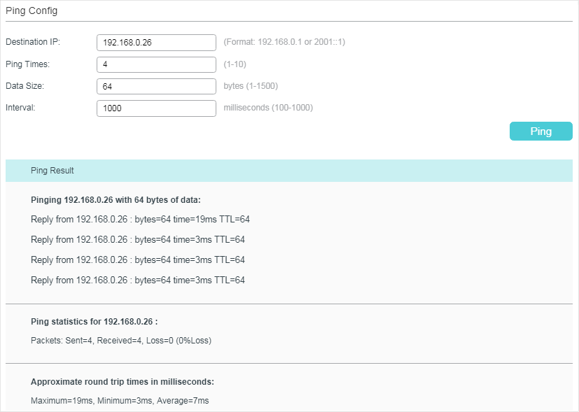
Follow these steps to test the connectivity between the switch and another device in the network:
1)In the Ping Config section, enter the IP address of the destination device for Ping test, set Ping times, data size and interval according to your needs, and then click Ping to start the test.
|
Destination IP |
Enter the IP address of the destination node for Ping test. Both IPv4 and IPv6 are supported. |
|
Ping Times |
Enter the number of times test data will be sent for Ping testing. It is recommended to use the default value of 4. |
|
Data Size |
Enter the size of the data sent for Ping testing. It is recommended to keep the default value of 64 bytes. |
|
Interval |
Specify the interval at which ICMP request packets are sent. It is recommended to keep the default value of 1000 milliseconds. |
2) In the Ping Result section, check the test results.
2.1.2Troubleshooting with Tracert Testing
You can use the Tracert tool to find the path from the switch to the destination, and test connectivity between the switch and routers along the path.
Choose the menu MAINTENANCE > Network Diagnostics > Tracert to load the following page.
Figure 2-1 Troubleshooting with Tracert Testing
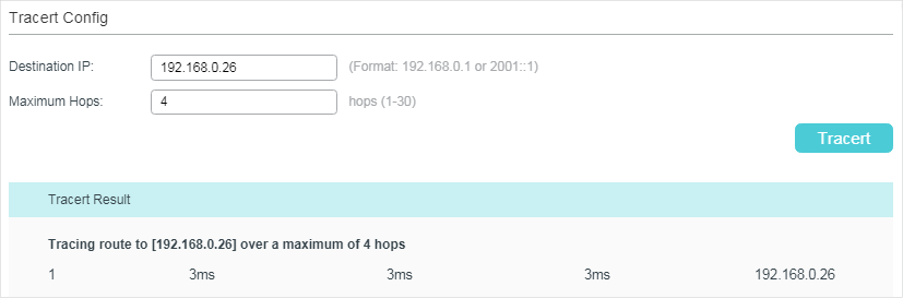
Follow these steps to test connectivity between the switch and routers along the path from the source to the destination:
1)In the Tracert Config section, enter the IP address of the destination, set the max hop, and then click Tracert to start the test.
|
Destination IP |
Enter the IP address of the destination device. Both IPv4 and IPv6 are supported. |
|
Maximum Hops |
Specify the maximum number of the route hops the test data can pass through. |
2)In the Tracert Result section, check the test results.
2.2Using the CLI
2.2.1Configuring the Ping Test
On privileged EXEC mode, you can use the following command to test the connectivity between the switch and one node of the network.
|
ping [ ip | ipv6 ] { ip_addr } [ -n count ] [ -l size ] [ -i interval ] Test the connectivity between the switch and destination device. ip: The type of the IP address for ping test should be IPv4. ipv6: The type of the IP address for ping test should be IPv6. ip_addr: The IP address of the destination node for ping test. If the parameter ip/ipv6 is not selected, both IPv4 and IPv6 addresses are supported, such as 192.168.0.100 or fe80::1234. count: Specify the amount of times to send test data for Ping testing. The values are from 1 to 10 times; the default is 4 times. size: Specify the size of the sending data for ping testing. The values are from 1 to 1500 bytes; the default is 64 bytes. interval: Specify the interval to send ICMP request packets. The values are from 100 to 1000 milliseconds; the default is 1000 milliseconds. |
The following example shows how to test the connectivity between the switch and the destination device with the IP address 192.168.0.10. Specify the ping times as 3, the data size as 1000 bytes and the interval as 500 milliseconds:
Switch#ping ip 192.168.0.10 -n 3 -l 1000 -i 500
Pinging 192.168.0.10 with 1000 bytes of data :
Reply from 192.168.0.10 : bytes=1000 time<16ms TTL=64
Reply from 192.168.0.10 : bytes=1000 time<16ms TTL=64
Reply from 192.168.0.10 : bytes=1000 time<16ms TTL=64
Ping statistics for 192.168.0.10:
Packets: Sent = 3 , Received = 3 , Lost = 0 (0% loss)
Approximate round trip times in milli-seconds:
Minimum = 0ms , Maximum = 0ms , Average = 0ms
2.2.2Configuring the Tracert Test
On privileged EXEC mode, you can use the following command to test the connectivity between the switch and routers along the path from the source to the destination:
|
tracert [ ip | ipv6 ] ip_addr [ maxHops ] Test the connectivity of the gateways along the path from the source to the destination. ip: The type of the IP address for tracert test should be IPv4. ipv6: The type of the IP address for tracert test should be IPv6. ip_addr: Enter the IP address of the destination device. If the parameter ip/ipv6 is not selected, both IPv4 and IPv6 addresses are supported, such as 192.168.0.100 or fe80::1234. maxHops: Specify the maximum number of the route hops the test data can pass though. The range is 1 to 30 hops; the default is 4 hops. |
The following example shows how to test the connectivity between the switch and the network device with the IP address 192.168.0.100. Set the maxhops as 2:
Switch#tracert 192.168.0.100 2
Tracing route to 192.168.0.100 over a maximum of 2 hops
1 8 ms 1 ms 2 ms 192.168.1.1
2 2 ms 2 ms 2 ms 192.168.0.100
Trace complete.
Default settings of Network Diagnostics are listed in the following tables.
Table 3-1Default Settings of Ping Config
|
Parameter |
Default Setting |
|
Destination IP |
192.168.0.1 |
|
Ping Times |
4 |
|
Data Size |
64 bytes |
|
Interval |
1000 milliseconds |
Table 3-2Default Settings of Tracert Config
|
Parameter |
Default Setting |
|
Destination IP |
192.168.0.100 |
|
Maximum Hops |
4 hops |