Configuring VPN
CHAPTERS
|
|
This guide applies to: TL-ER6120 v2, TL-ER6020 v2, TL-R600VPN v4. |

1.1Overview
VPN (Virtual Private Network) provides a means for secure communication between remote computers across a public wide area network (WAN), such as the internet. Virtual indicates the VPN connection is based on the logical end-to-end connection instead of the physical end-to-end connection. Private indicates users can establish the VPN connection according to their requirements and only specific users are allowed to use the VPN connection.
The core of VPN is to realize tunnel communication, which fulfills the task of data encapsulation, data transmission and data decompression via the tunneling protocol. Common tunneling protocols are Layer 2 tunneling protocol and Layer 3 tunneling protocol.
Figure 1-1 Typical Topology of VPN
1.2Supported Features
The router supports Layer 2 tunneling protocol (PPTP, L2TP) and Layer 3 tunneling protocol (IPSec).
PPTP
PPTP (Point-to-Point Tunneling Protocol) is a network protocol that enables the secure transfer of data from a remote client to a private enterprise server by creating a VPN across TCP/IP-based data networks. PPTP supports on-demand, multiprotocol, virtual private networking over public networks, such as the internet.
L2TP
L2TP (Layer 2 Tunneling Protocol) provides a way for a dialup user to make a virtual Point-to-Point Protocol (PPP) connection to an L2TP network server (LNS), which can be a security gateway. L2TP sends PPP frames through a tunnel between an L2TP access concentrator (LAC) and the LNS. Because of the lack of confidentiality inherent in the L2TP protocol, it is often implemented along with IPSec.
IPSec
IPSec (IP Security) can provide security services such as data confidentiality, data integrity and data authentication at the IP layer. IPSec uses IKE (Internet Key Exchange) to handle negotiation of protocols and algorithms based on the user-specified policy, and to generate the encryption and authentication keys to be used by IPSec. IPSec can be used to protect one or more paths between a pair of hosts, between a pair of security gateways, or between a security gateway and a host. The security gateway refers to a device which implements IPSec protocol. For example, a router or a firewall implementing IPSec is a security gateway.
To complete the IPSec VPN configuration, follow these steps:
1)Configure the IPSec Policy.
2)Verify the connectivity of the IPSec VPN tunnel.
Configuration Guidelines
For both ends of the VPN tunnel, the Pre-shared key, Proposal, Exchange Mode, and Encapsulation Mode should be identical.
For both ends of the VPN tunnel, the Remote Gateway, Local/Remote Subnet, Local/Remote ID Type should be matched.
2.1Configuring the IPSec Policy
2.1.1Configuring the Basic Parameters
Choose the menu VPN > IPSec > IPSec Policy and click Add to load the following page.
Figure 2-1 Configuring the Basic Parameters
Follow these steps to configure the basic parameters:
1)Specify the name of the IPSec Policy.
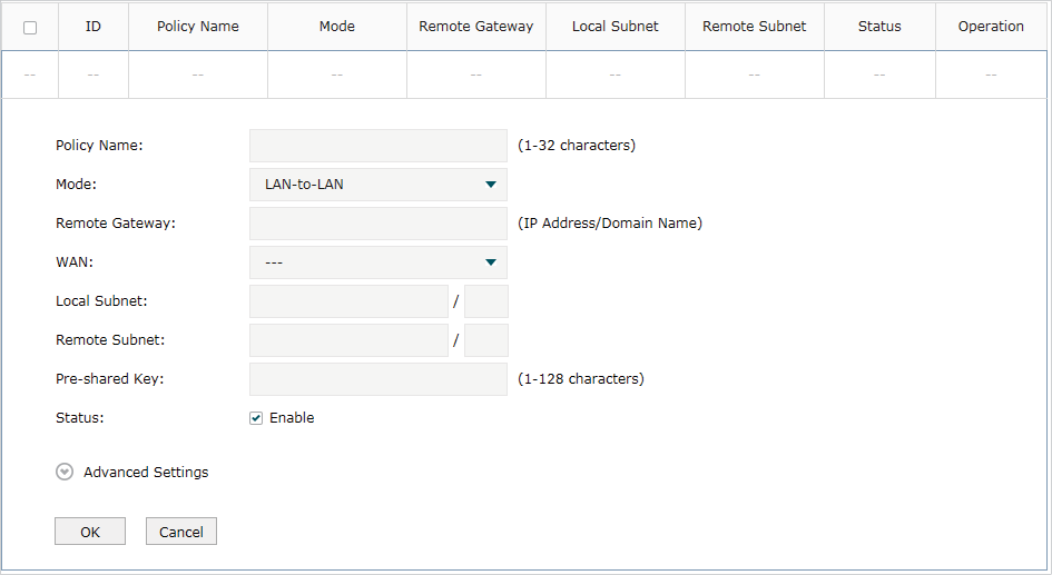
2)Configure the Network Mode. Select LAN-to-LAN when the network is connected to the other network. Select Client-to-LAN when a host is connected to the network.
When the LAN-to-LAN mode is selected, the following section will appear.

|
Remote Gateway |
Enter an IP address or a domain name (1 to 255 characters) as the remote gateway. 0.0.0.0 represents any IP address. Only when the negotiation mode is set to Responder Mode can you enter 0.0.0.0. |
|
WAN |
Specify the WAN port on which the IPSec tunnel is established. |
|
Local Subnet |
Specify the local network. (It’s always the IP address range of LAN on the local side of the VPN tunnel.) It’s formed from the IP address and subnet mask. |
|
Remote Subnet |
Specify the remote network. (It’s always the IP address range of LAN on the remote peer of the VPN tunnel.) It’s formed from the IP address and subnet mask. |
|
Pre-shared Key |
Specify the unique pre-shared key for both peers’ authentication. |
|
Status |
Choose to enable the IPSec policy. |
|
|
Note: The Local Subnet and Remote Subnet should not be in the same network segment when choosing LAN-to-LAN as the VPN mode. |

When the Client-to-LAN mode is selected, the following section will appear.

|
Remote Host |
Enter the IP address of the remote host. 0.0.0.0 represents any IP address. |
|
WAN |
Specify the WAN port on which the IPSec tunnel is established. |
|
Local Subnet |
Specify the local network. (This is the IP address range of the LAN on the local side of the VPN tunnel.) It’s formed from the IP address and subnet mask. |
|
Pre-shared Key |
Specify the unique pre-shared key for both peers’ authentication. |
|
Status |
Choose to enable the IPSec policy. |
3)Click OK.
2.1.2Configuring the Advanced Parameters
Advanced settings include IKEv1 phase-1 settings and IKEv1 phase-2 settings. IKEv1 phase-1 is used to authenticate both sides of the communication and establish the IKE SA. IKEv1 phase-2 is used to negotiate about keys and security related parameters, then establish the IPSec SA. It is suggested to keep the default advanced settings. You can complete the configurations according to your actual needs.
Configuring the IKE Phase-1 Parameters
Choose the menu VPN > IPSec > IPSec Policy and click Advanced Settings to load the following page.
Figure 2-2 Configuring the IKE Phase-1 Parameters
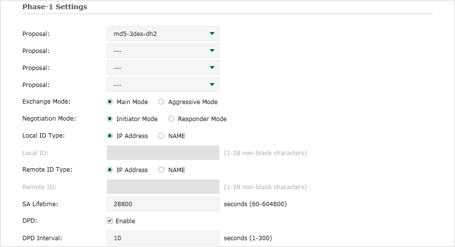
In the Phase-1 Settings section, configure the IKE phase-1 parameters and click OK.
|
Proposal |
Select the proposal for IKE negotiation phase 1 to specify the encryption algorithm, authentication algorithm and DH group. Up to four proposals can be selected. |
|
Exchange Mode |
Specify the IKE Exchange Mode as Main Mode or Aggressive Mode. By default, it is Main Mode. Main Mode: Main mode provides identity protection and exchanges more information, which applies to scenarios with higher requirements for identity protection. Aggressive Mode: Aggressive Mode establishes a faster connection but with lower security, which applies to scenarios with lower requirements for identity protection. |
|
Negotiation Mode |
Specify the IKE Negotiation Mode as Initiator Mode or Responder Mode. Initiator Mode means that the local device initiates a connection to the peer. Responder Mode means that the local device waits for the connection request initiated by the peer. You can keep this parameter as default. |
|
Local ID Type |
Specify the local ID type for IKE negotiation. IP Address: Use an IP address as the ID in IKE negotiation. It is the default type. NAME: Use a name as the ID in IKE negotiation. It refers to FQDN (Fully Qualified Domain Name). |
|
Local ID |
When the Local ID Type is configured as NAME, enter a name for the local device as the ID in IKE negotiation. |
|
Remote ID Type |
Specify the remote ID type for IKE negotiation. IP Address: Use an IP address as the ID in IKE negotiation. It is the default type. NAME: Use a name as the ID in IKE negotiation. It refers to FQDN (Fully Qualified Domain Name). |
|
Remote ID |
When the Remote ID Type is configured as NAME, enter a name of the remote peer as the ID in IKE negotiation . |
|
SA Lifetime |
Specify ISAKMP SA (Security Association) Lifetime in IKE negotiation. If the SA lifetime expired, the related ISAKMP SA will be deleted. |
|
DPD |
Check the box to enable or disable DPD (Dead Peer Detect) function. If enabled, the IKE endpoint can send a DPD request to the peer to inspect whether the IKE peer is alive. |
|
DPD Interval |
If DPD is triggered, specify the interval between sending DPD requests. If the IKE endpoint receives a response from the peer during this interval, it considers the peer alive. If the IKE endpoint does not receive a response during the interval, it considers the peer dead and deletes the SA. |
Configuring the IKE Phase-2 Parameters
Choose the menu VPN > IPSec > IPSec Policy and click Advanced Settings to load the following page.
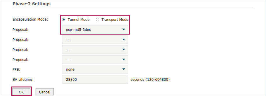
Figure 2-3 Configuring the IKE Phase-2 Parameters
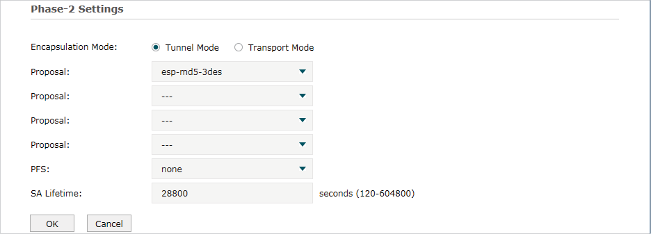
In the Phase-2 Settings section, configure the IKE phase-2 parameters and click OK.
|
Encapsulation Mode |
Specify the Encapsulation Mode as Tunnel Mode or Transport Mode. When both ends of the tunnel are hosts, either mode can be chosen. When at least one of the endpoints of a tunnel is a security gateway, such as a router or firewall, tunnel mode is recommended to ensure safety. |
|
Proposal |
Select the proposal for IKE negotiation phase 2 to specify the encryption algorithm, authentication algorithm and protocol. Up to four proposals can be selected. |
|
PFS |
Select the DH group to enable PFS (Perfect Forward Security) for IKE mode, then the key generated in phase 2 will be irrelevant with the key in phase 1, which enhance the network security. If you select None, it means PFS is disabled and the key in phase 2 will be generated based on the key in phase 1. |
|
SA Lifetime |
Specify IPSec SA (Security Association) Lifetime in IKE negotiation. If the SA lifetime expired, the related IPSec SA will be deleted. |
2.2Verifying the Connectivity of the IPSec VPN tunnel
Choose the menu VPN > IPSec > IPSec SA to load the following page.
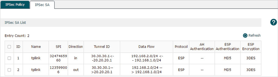
Figure 2-4 IPSec SA List
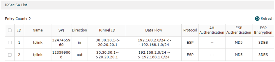
The IPSec SA List shows the information of the established IPSec VPN tunnel.
|
Name |
Displays the name of the IPSec policy associated with the SA. |
|
SPI |
Displays the SPI (Security Parameter Index) of the SA, including outgoing SPI and incoming SPI. The SPI of each SA is unique. |
|
Direction |
Displays the direction (in: incoming/out: outgoing) of the SA. |
|
Tunnel ID |
Displays the IP addresses of the local and remote peers. |
|
Data Flow |
Displays the Local Subnet and Remote Subnet/host covered by the SA. |
|
Protocol |
Displays the authentication protocol and encryption protocol used by the SA. |
|
AH Authentication |
Displays the AH authentication algorithm used by the SA. |
|
ESP Authentication |
Displays the ESP authentication algorithm used by the SA. |
|
ESP Encryption |
Displays the ESP encryption algorithm used by the SA. |
To complete the L2TP configuration, follow these steps:
1)Configure the VPN IP pool.
2)Configure L2TP globally.
3)Configure the L2TP server/client.
4)(Optional) Configure the L2TP users.
5)Verify the connectivity of the L2TP VPN tunnel.
Configuration Guidelines
When the network mode is configured as Client-to-LAN and the router acts as the L2TP server, you don’t need to configure the L2TP client on the router.
When the network mode is configured as LAN-to-LAN and the router acts as the L2TP client gateway, you don’t need to configure the L2TP users on the router.
3.1Configuring the VPN IP Pool
Choose the menu Preferences> VPN IP Pool > VPN IP Pool and click Add to load the following page.
Figure 3-1 Configuring the VPN IP Pool
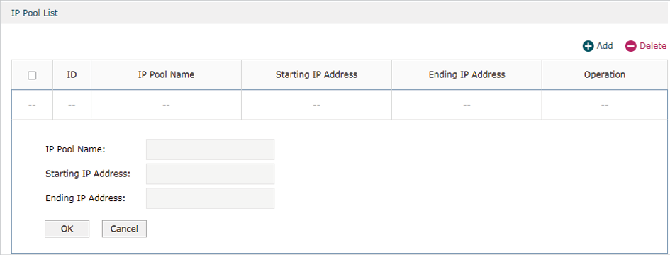
Follow these steps to configure the VPN IP Pool:
1)Specify the name of the IP Pool.
2)Specify the starting IP address and ending IP address for the IP Pool.
|
|
Note: •The starting IP address should not be greater than the ending IP address. •The ranges of IP Pools cannot overlap. |
3.2Configuring L2TP Globally
Choose the menu VPN> L2TP > Global Config to load the following page.
Figure 3-2 Configuring L2TP Globally
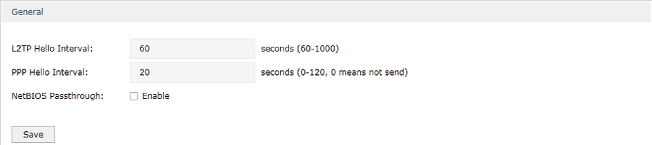
In the General section, configure L2TP parameters globally and click Save.
|
L2TP Hello Interval |
Specify the time interval of sending L2TP peer detect packets. |
|
PPP Hello Interval |
Specify the time interval of sending PPP peer detect packets. |
|
NetBIOS Passthrough |
Enable NetBIOS Passthrough function to allow NetBIOS packets to be broadcasted through VPN tunnel. |
3.3Configuring the L2TP Server
Choose the menu VPN> L2TP > L2TP Server and click Add to load the following page.
Figure 3-3 Configuring the L2TP Server
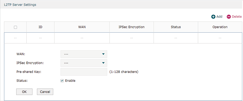
Follow these steps to configure the L2TP server:
1)Specify the WAN port used for L2TP tunnel.
2)Specify whether to enable the encryption for the tunnel.
|
IPSec Encryption |
Specify whether to enable the encryption for the tunnel. If enabled, the L2TP tunnel will be encrypted by IPSec (L2TP over IPSec). If you choose Auto, the L2TP server will determine whether to encrypt the tunnel according to the client ‘s encryption settings. |
3)Specify the Pre-shared Key for IKE authentication.
4)Enable the L2TP tunnel.
5)Click OK.
3.4Configuring the L2TP Client
Choose the menu VPN> L2TP > L2TP Client and click Add to load the following page.
Figure 3-4 Configuring the L2TP Client
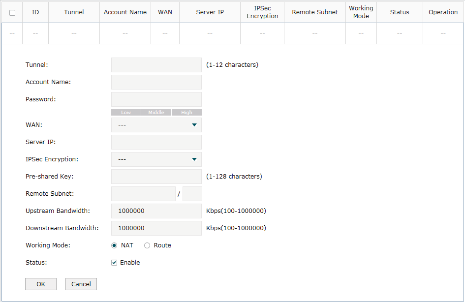
Follow these steps to configure the L2TP client:
1)Specify the name of the L2TP tunnel and configure other relevant parameters of the L2TP client according to your actual network environment.
|
Tunnel |
Specify the name of L2TP tunnel. |
|
Account Name |
Specify the account name of L2TP tunnel. It should be configured identically on server and client. |
|
Password |
Specify the password of L2TP tunnel. It should be configured identically on server and client. |
|
WAN |
Specify the WAN port used for L2TP tunnel. |
|
Server IP |
Specify the IP address or domain name of L2TP server. |
|
IPSec Encryption |
Specify whether to enable the encryption for the tunnel. If enabled, the L2TP tunnel will be encrypted by IPSec (L2TP over IPSec). |
|
Pre-shared Key |
Specify the Pre-shared Key for IKE authentication. |
|
Remote Subnet |
Specify the remote network. (It’s always the IP address range of LAN on the remote peer of the VPN tunnel.) It’s the combination of IP address and subnet mask. |
|
Upstream Bandwidth |
Specify the uptream limited rate in Kbps for L2TP tunnel. |
|
Downstream Bandwidth |
Specify the downstream limited rate in Kbps for L2TP tunnel. |
|
Working Mode |
Specify the Working Mode as NAT or Routing. NAT: NAT (Network Address Translation) mode allows the router to translate source IP address of L2TP packets to its WAN IP when forwarding L2TP packets. Route: Route mode allows the router to forward L2TP packets via routing protocol. |
|
Status |
Check the box to enable the L2TP tunnel. |
2)Click OK.
3.5(Optional) Configuring the L2TP Users
Choose the menu VPN> Users > Users and click Add to load the following page.
Figure 3-5 Configuring the L2TP User
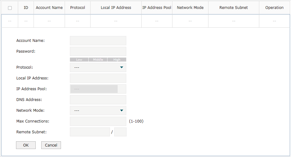
Follow these steps to configure the L2TP User:
1)Specify the account name and password of the L2TP User.
|
Account Name |
Specify the account name used for the VPN tunnel. This parameter should be the same with that of the L2TP client. |
|
Password |
Specify the password of user. This parameter should be the same with that of the L2TP client. |
2)Specify the protocol as L2TP and configure other relevant parameters according to your actual network environment.
|
Protocol |
Specify the protocol for the VPN tunnel. There are two types: L2TP and PPTP. |
|
Local IP Address |
Specify the local IP address of the tunnel. You can enter the LAN IP of the local device. |
|
IP Address Pool |
Specify the IP address pool from which the IP address will be assigned to the VPN client. The IP Pool referenced here can be created on the Preferences > VPN IP Pool page. |
|
DNS Address |
Specify the DNS address to be assigned to the VPN client (8.8.8.8 for example). |
|
Network Mode |
Specify the network mode. There are two modes: Client-to-LAN: Select this option when the L2TP/PPTP client is a single host. LAN-to-LAN: Select this option when the L2TP/PPTP client is a VPN gateway. The tunneling request is always initiated by a device. |
|
Max Connections |
Specify the maximum number of connections that the tunnel can support. |
|
Remote Subnet |
Specify a remote network. (This is the IP address range of the LAN on the remote peer of the L2TP/PPTP tunnel.) It’s the combination of IP address and subnet mask. |
3)Click OK.
3.6Verifying the Connectivity of L2TP VPN Tunnel
Choose the menu VPN> L2TP > Tunnel List to load the following page.
Figure 3-6 L2TP VPN Tunnel List
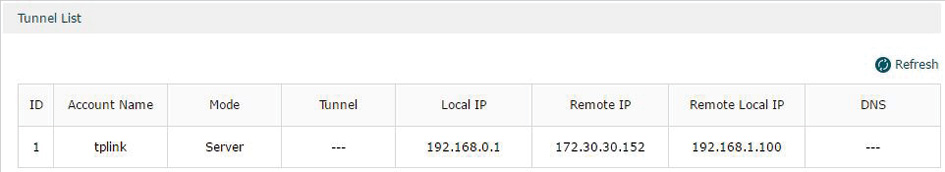
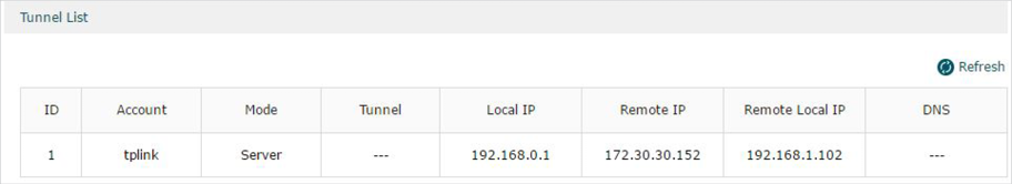
The Tunnel List shows the information of the established L2TP VPN tunnel.
|
Account Name |
Displays the account name of L2TP tunnel. |
|
Mode |
Displays whether the device is server or client. |
|
Tunnel |
Displays the name of the tunnel when the router is a L2TP client. |
|
Local IP |
Displays the local IP address of the tunnel. |
|
Remote IP |
Displays the remote real IP address of the tunnel. |
|
Remote Local IP |
Displays the remote local IP address of the tunnel. |
|
DNS |
Displays the DNS address of the tunnel. |
To complete the PPTP configuration, follow these steps:
1)Configure the VPN IP pool.
2)Configure PPTP globally.
3)Configure the PPTP server/client.
4)(Optional) Configure the PPTP users.
5)Verify the connectivity of the PPTP VPN tunnel.
Configuration Guidelines
When the network mode is configured as Client-to-LAN and the router acts as the PPTP server, you don’t need to configure a PPTP client on the router.
When the network mode is configured as LAN-to-LAN and the router acts as the PPTP client gateway, you don’t need to configure PPTP users on the router.
4.1Configuring the VPN IP Pool
Choose the menu Preferences> VPN IP Pool > VPN IP Pool and click Add to load the following page.
Figure 4-1 Configuring the VPN IP Pool
Follow these steps to configure the VPN IP Pool:
1)Specify the name of the IP Pool.
2)Specify the starting IP address and ending IP address for the IP Pool.
|
|
Note: •The starting IP address should not be greater than the ending IP address. •The ranges of IP Pools cannot overlap. |
4.2Configuring PPTP Globally
Choose the menu VPN> PPTP > Global Config to load the following page.
Figure 4-2 Configuring PPTP Globally
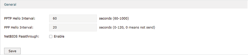
In the General section, configure PPTP parameters globally and click Save.
|
PPTP Hello Interval |
Specify the time interval of sending PPTP peer detect packets. |
|
PPP Hello Interval |
Specify the time interval of sending PPP peer detect packets. |
|
NetBIOS Passthrough |
Enable NetBIOS Passthrough function to allow NetBIOS packets to be broadcasted through VPN tunnel. |
4.3Configuring the PPTP Server
Choose the menu VPN> PPTP > PPTP Server and click Add to load the following page.
Figure 4-3 Configuring the PPTP Server
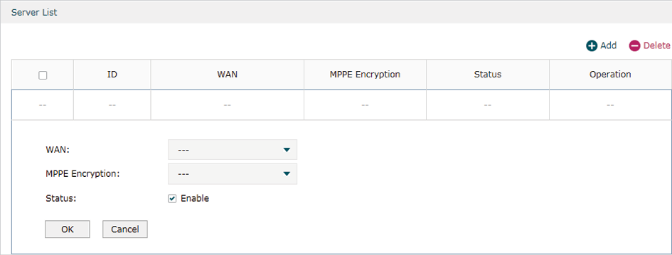
Follow these steps to configure the PPTP server:
1)Specify the WAN port used for PPTP tunnel.
2)Specify whether to enable the MPPE encryption for the PPTP tunnel.
3)Enable the PPTP tunnel.
4)Click OK.
4.4Configuring the PPTP Client
Choose the menu VPN> PPTP > PPTP Client and click Add to load the following page.
Figure 4-4 Configuring the PPTP Client
Follow these steps to configure the PPTP client:
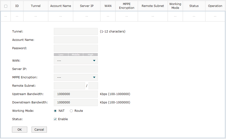
1)Specify the name of the PPTP tunnel and configure other relevant parameters of the PPTP client according to your actual network environment.
|
Tunnel |
Specify the name of PPTP tunnel. |
|
Account Name |
Specify the account name of PPTP tunnel. It should be configured identically on server and client. |
|
Password |
Specify the password of PPTP tunnel. It should be configured identically on server and client. |
|
WAN |
Specify the WAN port used for PPTP tunnel. |
|
Server IP |
Specify the IP address or domain name of PPTP server. |
|
MPPE Encryption |
Specify whether to enable the encryption for the tunnel. If enabled, the PPTP tunnel will be encrypted by MPPE. |
|
Remote Subnet |
Specify the remote network. (It’s always the IP address range of LAN on the remote peer of the VPN tunnel.) It’s the combination of IP address and subnet mask. |
|
Upstream Bandwidth |
Specify the uptream limited rate in Kbps for PPTP tunnel. |
|
Downstream Bandwidth |
Specify the downstream limited rate in Kbps for PPTP tunnel. |
|
Working Mode |
Specify the Working Mode as NAT or Routing. NAT: NAT (Network Address Translation) mode allows the router to translate source IP address of PPTP packets to its WAN IP when forwarding PPTP packets. Route: Route mode allows the router to forward PPTP packets via routing protocol. |
|
Status |
Check the box to enable the PPTP tunnel. |
2)Click OK.
4.5Configuring the PPTP Users
Choose the menu VPN> Users > Users and click Add to load the following page.
Figure 4-5 Configuring the PPTP User
Follow these steps to configure the PPTP User:
1)Specify the account name and password of the PPTP User.
|
Account Name |
Specify the account name used for the VPN tunnel. This parameter should be the same as that of the PPTP client. |
|
Password |
Specify the password of users. This parameter should be the same as that of the PPTP client. |
2)Specify the protocol as PPTP and configure other relevant parameters according to your actual network environment.
|
Protocol |
Specify the protocol for the VPN tunnel. There are two types: L2TP and PPTP. |
|
Local IP Address |
Specify the local IP address of the tunnel. You can enter the LAN IP of the local device. |
|
IP Address Pool |
Specify the IP address pool from which the IP address will be assigned to the VPN client. The IP Pool referenced here can be created on the Preferences > VPN IP Pool page. |
|
DNS Address |
Specify the DNS address to be assigned to the VPN client (8.8.8.8 for example). |
|
Network Mode |
Specify the network mode. There are two modes: Client-to-LAN: Select this option when the PPTP/PPTP client is a single host. LAN-to-LAN: Select this option when the PPTP/PPTP client is a VPN gateway. The tunneling request is always initiated by a device. |
|
Max Connections |
Specify the maximum number of connections that the tunnel can support. |
|
Remote Subnet |
Specify a remote network. (This is the IP address range of the LAN on the remote peer of the PPTP/PPTP tunnel.) It’s the combination of IP address and subnet mask. |
3)Click OK.
4.6Verifying the Connectivity of PPTP VPN Tunnel
Choose the menu VPN> PPTP > Tunnel List to load the following page.
Figure 4-6 PPTP VPN Tunnel List
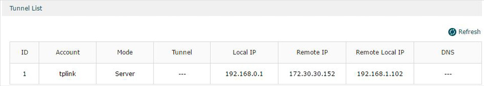
The Tunnel List shows the information of the established PPTP VPN tunnel.
|
Account |
Displays the account name of PPTP tunnel. |
|
Mode |
Displays whether the device is server or client. |
|
Tunnel |
Displays the name of the tunnel when the router is a PPTP client. |
|
Local IP |
Displays the local IP address of the tunnel. |
|
Remote IP |
Displays the remote real IP address of the tunnel. |
|
Remote Local IP |
Displays the remote local IP address of the tunnel. |
|
DNS |
Displays the DNS address of the tunnel. |
5.1Example for Configuring IPSec VPN
5.1.1Network Requirements
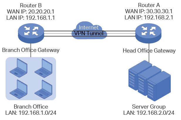
A business requires a highly secure connection between one of the branch offices and the head office. Thus we can build the site-to-site IPSec VPN tunnel between the branch office and the head office to establish the virtual private connection.
5.1.2Network Topology
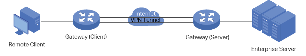
As is shown below, computers in the branch office are connected to the banch office VPN gateway router B via the LAN port, and the internal server group is connected to the head office VPN gateway router A via the LAN port.
Figure 5-1 Site-to-Site IPSec VPN Topology
5.1.3Configuration Scheme
To meet the requirements, configure IPSec policy on Router A and Router B. (As the network topology above shows, two VPN gateways are connected via the internet, so the network mode should be configured as LAN-to-LAN.) Then verify whether the IPSec VPN tunnel is established successfully.
The following section provides the configuration procedure.
5.1.4Configuration Procedure
Follow the steps below to configure IPSec policy on Router A and Router B:
Configuring the Router A
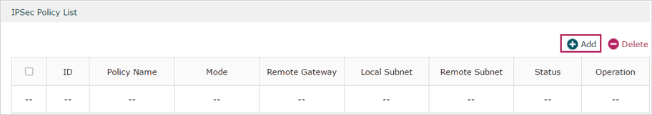
1)Choose the menu VPN > IPSec > IPSec Policy to load the following page. Click Add.
Figure 5-2 IPSec Policy List
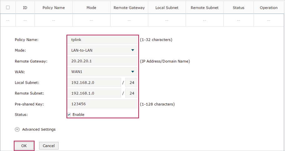
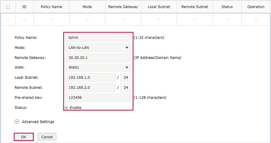
2)The following page will appear. Specify the IPSec Policy Name as tplink and configure the Mode as LAN-to-LAN as the network is connected to the other network, then configure other relevant parameters. Keep Enable selected as the Status of this entry. Click OK.
Figure 5-3 Configuring the IPSec Policy
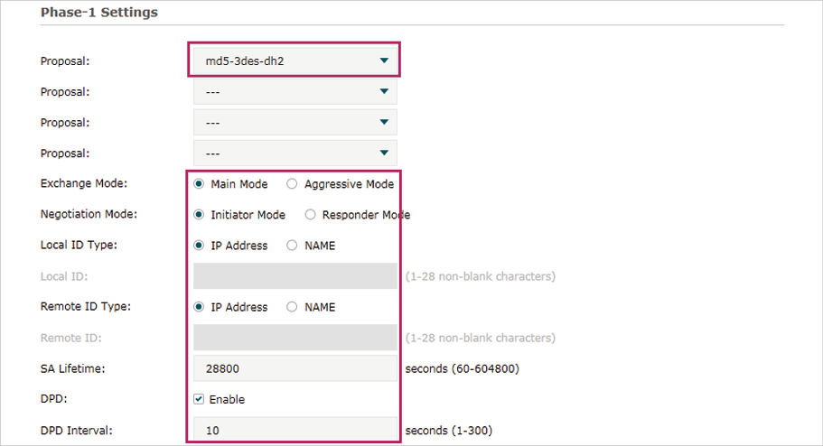
3)Choose the menu VPN > IPSec > IPSec Policy and click Advanced Settings to load the following page. Advanced settings include IKEv1 phase-1 settings and IKEv1 phase-2 settings. You can keep the default advanced settings.
In the Phase-1 Settings section, configure the IKE phase-1 parameters and click OK.
Figure 5-4 Configuring the IKE Phase-1 Parameters
In the Phase-2 Settings section, configure the IKE phase-2 parameters and click OK.
Figure 5-5 Configuring the IKE Phase-2 Parameters
Configuring the Router B
1)Choose the menu VPN > IPSec > IPSec Policy to load the following page. Click Add.
Figure 5-6 IPSec Policy List
2)The following page will appear. Specify the IPSec Policy Name as tplink and configure the Mode as LAN-to-LAN as the network is connected to the other network, then configure other relevant parameters. Keep Enable selected as the Status of this entry. Click OK.
Figure 5-7 Configuring the IPSec Policy
3)Choose the menu VPN > IPSec > IPSec Policy and click Advanced Settings to load the following page. Advanced settings include IKEv1 phase-1 settings and IKEv1 phase-2 settings. You can keep the default advanced settings.
In the Phase-1 Settings section, configure the IKE phase-1 parameters and click OK.
Figure 5-8 Configuring the IKE Phase-1 Parameters
In the Phase-2 Settings section, configure the IKE phase-2 parameters and click OK.
Figure 5-9 Configuring the IKE Phase-2 Parameters
Verifying the connectivity of the IPSec VPN tunnel
On Router A or Router B, choose the menu VPN > IPSec > IPSec SA to view the information of the established IPSec VPN tunnel. Here we take router A for example.
Figure 5-10 Viewing the IPSec SA
5.2Example for Configuring L2TP VPN
5.2.1Network Requirements
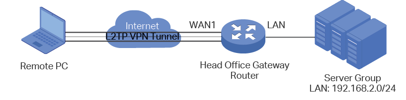
Employees out of the office need to communicate with the head office and access the internal resources at any time. And the communication data needs to be well protected. Thus we can build the remote access VPN tunnel between the employees on official business and the gateway device of the head office.
In this scenario, both PPTP and L2TP can be used. Here we take L2TP VPN as an example.
Figure 5-11 Remote Access L2TP VPN Topology
5.2.2Configuration Scheme
To meet the requirements, configure L2TP server on the router, and configure L2TP client on the remote PC. For the remote PC, use Windows built-in L2TP software or third-party L2TP software to connect to L2TP server. Then verify whether the L2TP VPN tunnel is established successfully.
The following section provides the configuration procedure.
5.2.3Configuration Procedure
Follow the steps below to configure L2TP VPN on the router and PC:
Configuring the router
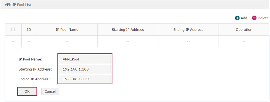
1)Choose the menu Preferences > VPN IP Pool > VPN IP Pool to load the configuration page, and click Add. Specify the pool name as VPN_Pool, and enter the starting/ending IP address.
Figure 5-12 Configuring the VPN IP Pool
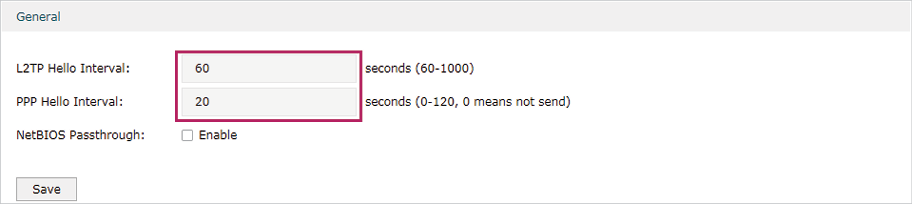
2)Choose the menu VPN> L2TP > Global Config to load the following page. You can keep the L2TP/PPP hello interval as the default value.
Figure 5-13 Configuring L2TP Globally
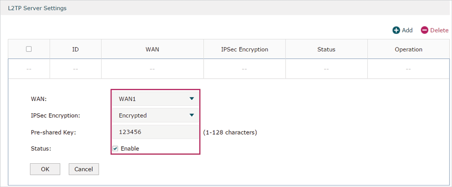
3)Choose the menu VPN> L2TP > L2TP Server to load the configuration page, and click Add. Specify WAN1 as the outgoing interface of L2TP VPN tunnel, enable IPSec encryption and specify the pre-shared key as 123456.
Figure 5-14 Configuring the L2TP Server
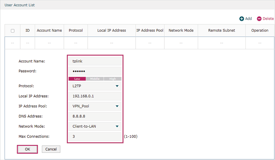
4)Choose the menu VPN> Users > Users to load the configuration page, and click Add. Specify the account name as tplink, and enter the password 123456. Select the protocol as L2TP, specify the LAN IP (192.168.0.1) as the local IP address of the gateway router, select VPN_Pool as the IP address pool to assign an IP address for the L2TP client, enter the DNS address (for example, 8.8.8.8), select the network mode as Client-to-LAN as the VPN gateway is connected to a host, specify the max connections as 3, then click OK.
Figure 5-15 Configuring the VPN User
Configuring the Remote PC
For remote PC, use Windows built-in L2TP software or third-party L2TP software to connect to L2TP server. For more information, you can refer to our official website:
http://www.tp-link.com/us/faq-1629.html
Verifying the connectivity of the L2TP VPN tunnel
On the router, choose the menu VPN> L2TP > Tunnel List to verify the connectivity of the L2TP VPN tunnel.
Figure 5-16 Viewing the L2TP VPN Tunnel
5.3Example for Configuring PPTP VPN
5.3.1Network Requirements
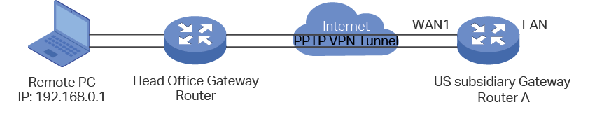
The employees at headquarters need to access the network resources through the server at the US subsidiary via a secure connection. Thus we can build the remote access VPN tunnel between the employees at headquarter and the gateway device of the US subsidiary.
In this scenario, both PPTP and L2TP can be used. Here we take PPTP VPN as an example.
Figure 5-17 Remote Access PPTP VPN Topology
5.3.2Configuration Scheme
To meet the requirements, configure PPTP server on Router A, and configure PPTP client on the remote PC. For Router A, make sure to add a Multi-Nets NAT entry. This will ensure Router A will not drop the packets sent from the remote PC. For the remote PC, use Windows built-in PPTP software or third-party PPTP software to connect to the PPTP server. Then verify whether the PPTP VPN tunnel is established successfully.
The following section provides the configuration procedure.
5.3.3Configuration Procedure
Follow the steps below to configure PPTP VPN on Router A and PC:
Configuring Router A
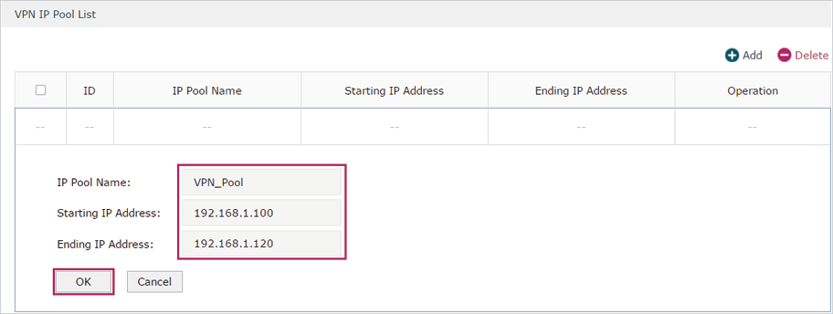
1)Choose the menu Preferences > VPN IP Pool > VPN IP Pool to load the configuration page, and click Add. Specify the pool name as VPN_Pool, and enter the starting/ending IP address.
Figure 5-18 Configuring the VPN IP Pool
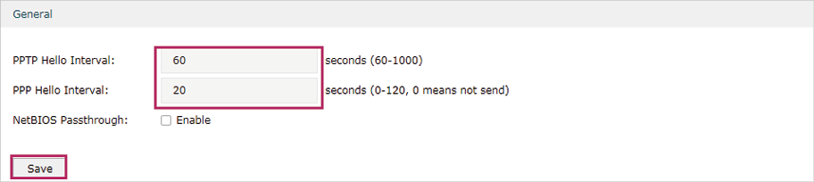
2)Choose the menu VPN> PPTP > Global Config to load the following page. You can keep the PPTP/PPP hello interval as the default value.
Figure 5-19 Configuring PPTP Globally
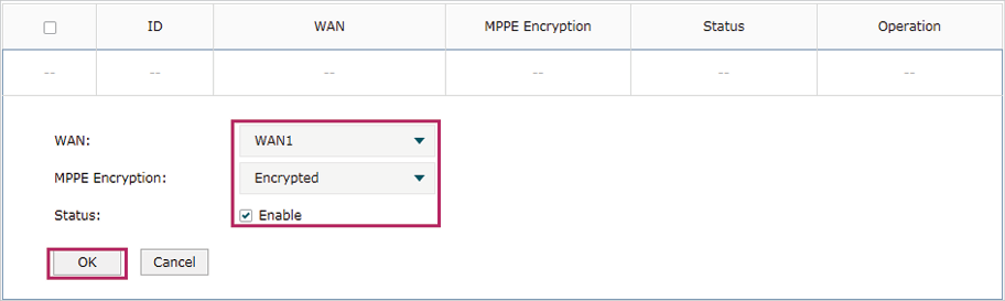
3)Choose the menu VPN> PPTP > PPTP Server to load the configuration page, and click Add. Specify WAN1 as the outgoing interface of PPTP VPN tunnel, enable MPPE encryption.
Figure 5-20 Configuring the PPTP Server
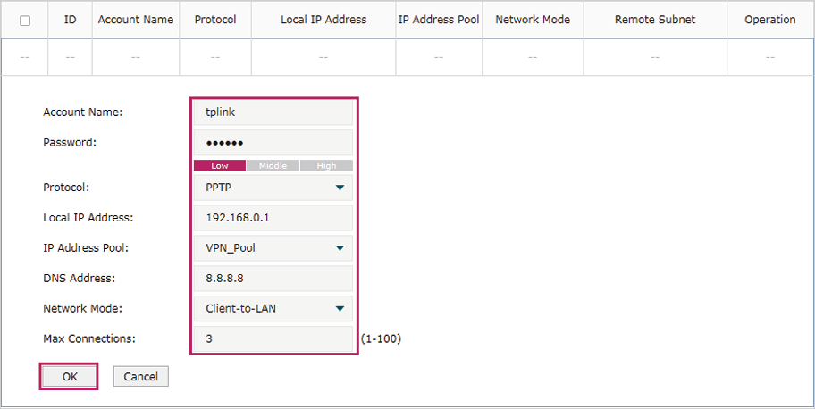
4)Choose the menu VPN> Users > Users to load the configuration page, and click Add. Specify the account name as tplink, and enter the password 123456. Select the protocol as PPTP, specify the LAN IP (192.168.0.1) as the local IP address of the gateway router, select VPN_Pool as the IP address pool to assign an IP address for the PPTP client, enter the DNS address (for example, 8.8.8.8), select the network mode LAN-to-LAN as the network is connected to the other network, specify the max connections as 3, then click OK.
Figure 5-21 Configuring the VPN User
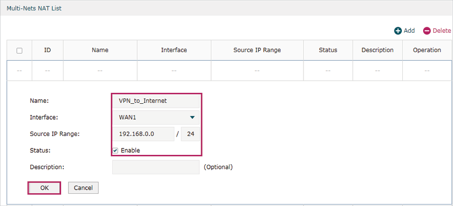
5)Choose the menu Tramsmission > NAT > Multi-Nets NAT to load the configuration page, and click Add. Specify the entry name as VPN_to_Internet, and choose WAN1 as the outgoing interface. Specify the LAN subnet (192.168.0.0) on which the employees are as the Source IP Range, Keep Enable selected as the Status of this entry. Click OK.
Figure 5-22 Adding the Multi-Nets NAT Entry
Configuring the Remote PC
For remote PC, use Windows built-in PPTP software or third-party PPTP software to connect to PPTP server. For more information, you can refer to our official website:
http://www.tp-link.com/us/faq-1629.html
Verifying the connectivity of the PPTP VPN tunnel
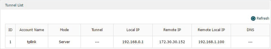
On the router, choose the menu VPN> PPTP > Tunnel List to verify the connectivity of the PPTP VPN tunnel.
Figure 5-23 Viewing the PPTP VPN Tunnel