Configuring VLAN-VPN
CHAPTERS
2. Basic VLAN VPN Configuration
3. Flexible VLAN VPN Configuration
5. Appendix: Default Parameters
|
|
This guide applies to: T2500G-10TS v2 or above, T2600G-18TS v2 or above, T2600G-28TS v3 or above, T2600G-28MPS v3 or above, T2600G-28SQ v1 or above, T2600G-52TS v3 or above. |

1.1Overview
VLAN VPN (Virtual Private Network) is an easy-to-implement layer 2 VLAN technology, and it is usually deployed at the edge of the ISP (Internet Service Provider) network.
With VLAN VPN, when forwarding packets from the customer network to the ISP network, the switch adds an outer tag to the packets with outer VLAN ID. Thus, packets can be transmitted through ISP networks with double VLAN tags. In the ISP network, packets are forwarded according to the outer VLAN tag (VLAN tag of the ISP network), while the inner VLAN tag is treated as part of the payload. When forwarding packets from the ISP network to the customer network, the switch remove the outer VLAN tag of the packets. Thus, packets are forwarded according to the inner VLAN tag (VLAN tag of the customer network) in the customer network.
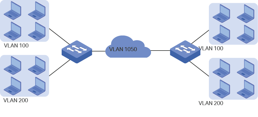
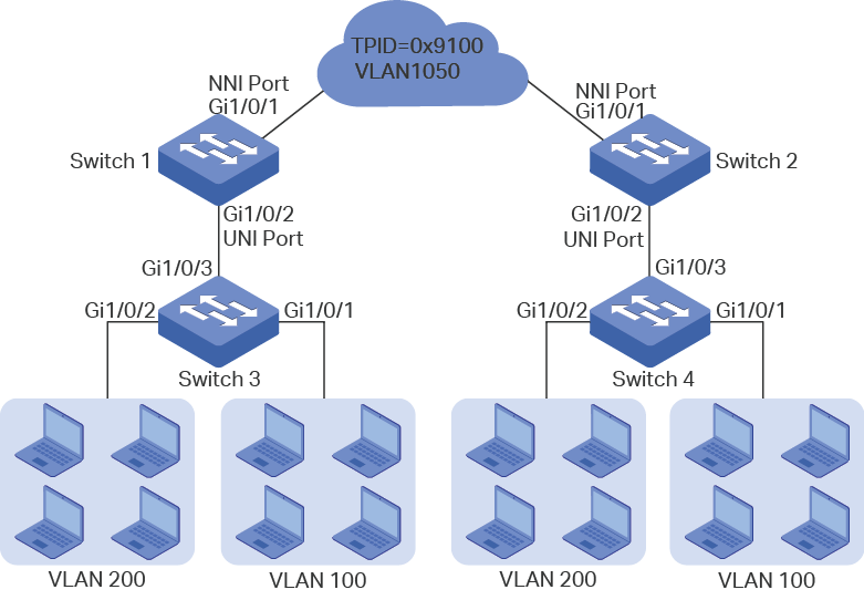
The following figure shows the typical application scenario of VLAN VPN. To realize the communication between two customer VLANs across the ISP network, you can configure VLAN VPN at the ISP edge switches to allow packets from customer VLAN 100 and VLAN 200 to be forwarded through the ISP network with the outer tag of VLAN 1050.
Figure 1-1 Application Scenario of VLAN VPN
1.2Supported Features
The VLAN VPN function includes: basic VLAN VPN and flexible VLAN VPN (VLAN mapping).
Basic VLAN VPN
All packets from customer VLANs are encapsulated with the same VLAN tag of the ISP network, and sent to the ISP network. Additionally, you can set the TPID (Tag Protocol Identifier) for compatibility with devices in the ISP network.
Flexible VLAN VPN
You can configure different VLANs in the customer network to map to different VLANs in the ISP network.
When the switch receives a packet with the customer network tag, the switch will check the VLAN Mapping List. If a match is found, the switch encapsulates the packet with the corresponding VLAN tag of the ISP network, and forwards it to the corresponding port. If no match is found, the switch process the packet in rules of MAC VLAN, Protocol VLAN and 802.1Q VLAN. For untagged packets, the switch directly processes them in rules of MAC VLAN, Protocol VLAN and 802.1Q VLAN.
To complete the basic VLAN VPN configuration, follow these steps:
1)Configure 802.1Q VLAN.
2)Configure NNI ports and UNI ports.
3)Enable VLAN VPN globally.
Configuration Guidelines
The TPID preset by the switch is 0x8100. If the devices in the ISP network do not support this value, you should change it to ensure VLAN VPN packets sent to the ISP network can be recognized and forwarded by devices of other manufacturers.
You can go to 802.1Q VLAN section to specify the Ingress Checking feature according to your needs. If the Ingress Checking is enabled, the port will perform this operation first then process the packets based on the VLAN VPN configuration. If Ingress Checking is disabled, the port will process the packets directly based on the VLAN VPN configuration.
2.1Using the GUI
2.1.1Configuring 802.1Q VLAN
Before configuring VLAN VPN, create 802.1Q VLAN add ports to corresponding VLANs and configure Ingress Checking on ports according to your needs. For details, refer to Configuring 802.1Q VLAN.
2.1.2Configuring Basic VLAN VPN
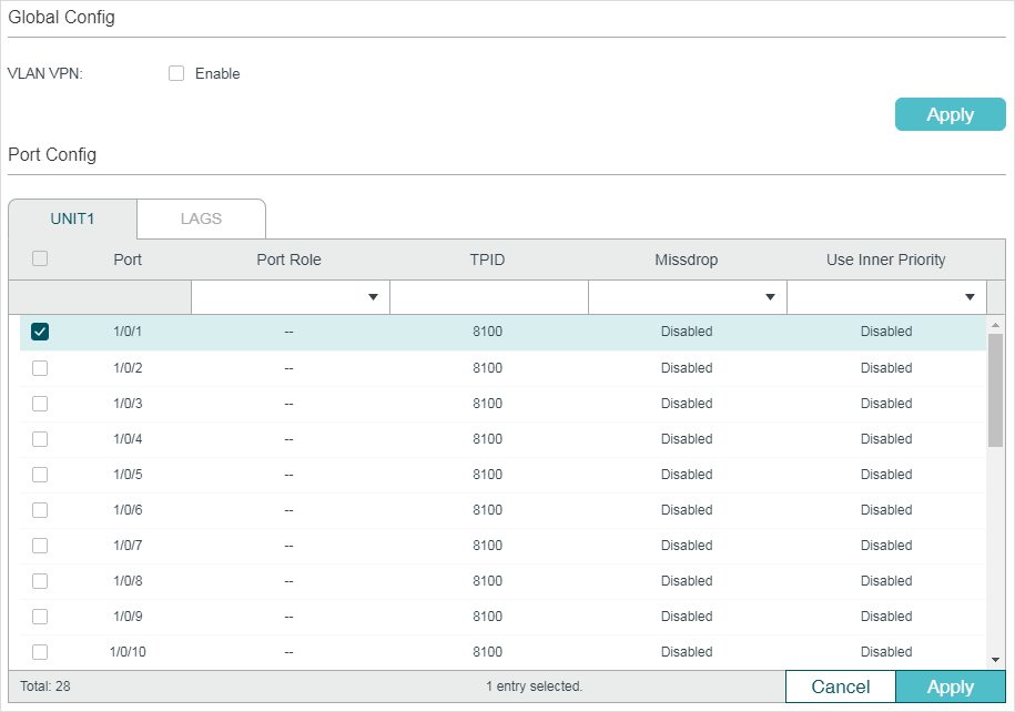
Choose the menu L2 FEATURES > VLAN > VLAN VPN > VPN Config to load the following page.
Figure 2-1 Basic VPN Configuration
Follow these steps to configure the basic VLAN VPN parameters:
1)In the Global Config section, enable VLAN VPN globally, and click Apply.
|
VLAN VPN |
Enable the VLAN VPN function globally. |
2)In the VPN Port Config section, select on or more ports and configure the corresponding parameters. Click Apply.
|
Port Role |
Select the port role that will take effect in the VLAN VPN function. NNI: NNI ports are usually edge ports connected to the ISP network, and the packets forwarded by these port have outer VLAN tags. UNI: UNI ports are usually connected to the customer network. The outer VLAN tags will be added or removed when the packets are forwarded by the VPN port. Note: The direct shift between ports modes UNI and NNI is not supported. To switch from the current mode to another mode, you can change the port tole to “--” first. |
|
TPID |
Specify the value of TPID. TPID is a field of VLAN tag and is modified to make the double tagged packets identifiable to devices from different vendors. |
|
Missdrop |
Enable the Missdrop feature. This option only can take effect on tagged packets. With Missdrop enabled, the tagged packets that don’t match the VLAN Mapping entries will be dropped. It is available only when the port role is UNI. |
|
Use Inner Priority |
Enable this function and the switch will determine the forwarding sequence of the packets according to the 802.1p priority of the inner VLAN tag. It is available only when the port role is UNI. |
|
|
Note: The PVID of the UNI port should be specified as the VLAN ID of the ISP VLAN. The member port of an LAG (Link Aggregation Group) follows the configuration of the LAG and not its own. The configurations of the port can take effect only after it leaves the LAG. |

2.2Using the CLI
2.2.1Configuring 802.1Q VLAN
Before configuring VLAN VPN, create 802.1Q VLAN, add ports to corresponding VLANs and configure Ingress Checking on ports according to your needs. For details, refer to Configuring 802.1Q VLAN.
2.2.1Configuring Basic VLAN VPN
Follow these steps to configure basic VLAN VPN:
|
Step 1 |
configure Enter global configuration mode. |
|
Step 2 |
dot1q-tunnel Enable the VLAN VPN feature globally. |
|
Step 3 |
interface {fastEthernet port | range fastEthernet port-list | gigabitEthernet port | range gigabitEthernet port-list | ten-gigabitEthernet port | range ten-gigabitEthernet port-list | port-channel port-channel-id | range port-channel port-channel-list} Enter interface configuration mode. |
|
Step 4 |
switchport dot1q-tunnel mode { nni | uni } Select the port role that will take effect in the VLAN VPN function. nni : NNI ports are usually connected to the ISP network, and the packets forwarded by these port have outer VLAN tags. uni : UNI ports are usually connected to the customer network. The outer VLAN tags will be added or removed when the packets are forwarded by the VPN port. Note: The direct shift between ports modes uni and nni is not supported. To switch from the current mode to another mode, you can use no switchport dot1q-tunnel mode to disable the current mode. |
|
Step 5 |
switchport dot1q-tunnel tpid tpid Specify the value of TPID. TPID is a field of VLAN tag and is modified to make the double tagged packets identifiable to devices from different vendors. tpid: Enter the IPID for the port. It must be 4 Hex integers. By default, it is 8100. |
|
Step 6 |
switchport dot1q-tunnel missdrop Enable the Missdrop feature. This option only can take effect on tagged packets. With Missdrop enabled, the tagged packets that don’t match the VLAN Mapping entries will be dropped. By default, it is disabled. It is available only when the port mode is UNI. |
|
Step 7 |
switchport dot1q-tunnel use_inner_priority Enable this function and the switch will determine the forwarding sequence of the packets according to the 802.1p priority of the inner VLAN tag. By default, it is disabled. It is available only when the port mode is UNI. |
|
Step 8 |
show dot1q-tunnel Verify the global configuration of VLAN VPN. |
|
Step 9 |
show dot1q-tunnel interface Verify the interface configuration of basic VLAN VPN. |
|
Step 10 |
end |
|
Step 11 |
copy running-config startup-config Save the settings in the configuration file. |
The following example shows how to enable the VLAN VPN feature globally, set port 1/0/1 of switch as the UNI port and 1/0/2 as the NNI port:
Switch#configure
Switch(config)#dot1q-tunnel
Switch(config)#interface gigabitEthernet 1/0/1
Switch(config-if)#switchport dot1q-tunnel mode uni
Switch(config-if)#exit
Switch(config)#interface gigabitEthernet 1/0/2
Switch(config-if)#switchport dot1q-tunnel mode nni
Switch(config-if)#show dot1q-tunnel
VLAN VPN Mode: Enabled
Mapping Mode: Disabled
Switch(config-if)#show dot1q-tunnel interface
Port Type Tpid Use Inner Priority LAG
------- ------- ------- ------------------ ---
Gi1/0/1 UNI 0x8100 Disable N/A
Gi1/0/2 NNI 0x8100 Enable N/A
...
Switch(config-if)#end
Switch#copy running-config startup-config
3Flexible VLAN VPN Configuration
To complete the flexible VLAN VPN configuration, follow these steps:
1)Configure 802.1Q VLAN and basic VLAN VPN.
2)Configure VLAN mapping.
Configuration Guidelines
Before you start, configure 802.1Q VLAN and the basic VLAN VPN.
You can specify the PVID of the UNI port according to your needs. The untagged packets and the tagged packets that don’t the VLAN mapping entry may be added the outer VLAN tag with this PVID according to your configuration.
3.1Using the GUI
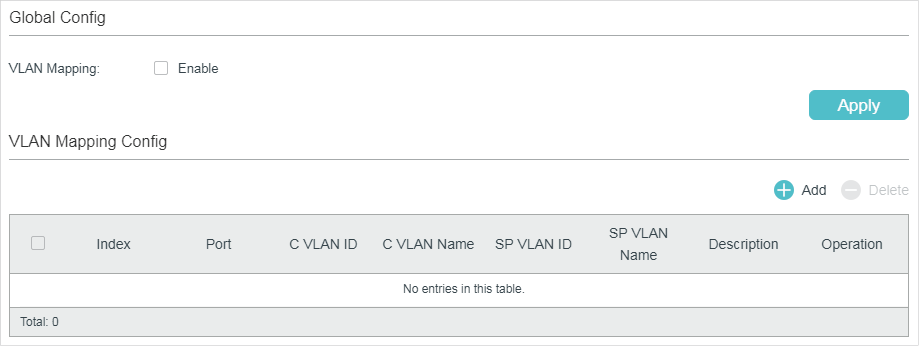
Choose the menu L2 FEATURES > VLAN > VLAN VPN > VLAN Mapping to load the following page.
Figure 3-1 Enable Flexible VLAN VPN
Follow these steps to configure flexible VLAN VPN:
1)In the Global Config section, enable VLAN mapping globally and click Apply.
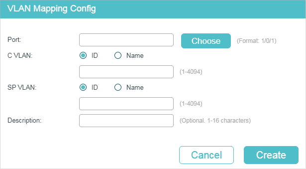
2)In the VLAN Mapping Config section, click  to load the following page. Configure the following parameters.
Figure 3-2 Create VLAN Mapping Entry
|
Port |
Choose a UNI port to enable VLAN mapping. Usually, ports that are connected to the customer network are set as UNI ports. You can also enter the port number in 1/0/1 format. |
|
C VLAN |
Specify the customer VLAN of the UNI port by entering the VLAN ID or VLAN Name. |
|
SP VLAN |
Specify the ISP VLAN of the UNI port by entering the VLAN ID or VLAN Name. |
|
Description |
Give a description to identify the VLAN Mapping. |
3)Click Create.
3.2Using the CLI
Follow these steps to configure flexible VLAN VPN:
|
Step 1 |
configure Enter global configuration mode. |
|
Step 2 |
dot1q-tunnel mapping Enable VLAN mapping globally. |
|
Step 3 |
interface {fastEthernet port | range fastEthernet port-list | gigabitEthernet port | range gigabitEthernet port-list | ten-gigabitEthernet port | range ten-gigabitEthernet port-list | port-channel port-channel-id | range port-channel port-channel-list} Enter interface configuration mode. |
|
Step 4 |
switchport dot1q-tunnel mapping c-vlan sp-vlan [ descript ] Set VLAN mapping entries for the specified port. c vlan: Enter VLAN ID of the customer network. sp vlan: Enter VLAN ID of the ISP network. descript: Give a description to identify the VLAN Mapping. |
|
Step 5 |
end Return to privileged EXEC mode. |
|
Step 6 |
copy running-config startup-config Save the settings in the configuration file. |
The following example shows how to enable VLAN mapping and set a VLAN mapping entry named mapping1 on port 1/0/3 to map customer network VLAN 15 to ISP network VLAN 1040:
Switch#configure
Switch(config)#dot1q-tunnel mapping
Switch(config)#show dot1q-tunnel
VLAN VPN Mode: Enabled
Mapping Mode: Enabled
Switch(config)#interface gigabitEthernet 1/0/3
Switch(config-if)#switchport dot1q-tunnel mapping 15 1040 mapping1
Switch(config-if)#show dot1q-tunnel mapping
Port C-VLAN SP-VLAN Name
----------- ---------- ------------ -----------
Gi1/0/3 15 1040 mapping1
Switch(config-if)#end
Switch#copy running-config startup-config
4.1Example for Basic VLAN VPN
4.1.1Network Requirements
A company has two stations, and the computers belong to VLAN 100 and VLAN 200 respectively. The ISP VLAN is VLAN 1050 and the TPID adopted by the ISP network is 0x9100.
The two stations need to communicate with each other through the ISP network. And it is required that the traffic from VLAN 100 and VLAN 200 should be transmitted in VLAN 1050.
Figure 4-1 Network Topology
4.1.2Configuration Scheme
To meet the requirement that all the traffic from VLAN 100 and VLAN 200 should be transmitted through VLAN 1050, users can configure basic VLAN VPN on Switch 1 and Switch 2 to allow packets sent with double VLAN tags, and thus ensure the communication between them. The general configuration procedure is as follows:
Here we only introduce the configuration schemes on switch 1 and switch 3, for the configurations on switch 2 are the same as those on switch 1, and the configurations on switch 4 are the same as those on switch 3.
1)Configure 802.1Q VLAN on switch 1. The parameters are shown below:
|
VLAN 100 |
VLAN 200 |
VLAN 1050 |
PVID |
|
|
Port 1/0/1 |
- |
- |
Tagged |
1 |
|
Port 1/0/2 |
Tagged |
Tagged |
Untagged |
1050 |
2)Configure 802.1Q VLAN on switch 3. The parameters are shown below:
|
VLAN 100 |
VLAN 200 |
PVID |
|
|
Port 1/0/1 |
- |
Untagged |
100 |
|
Port 1/0/2 |
Untagged |
- |
200 |
|
Port 1/0/3 |
Tagged |
Tagged |
1 |
3)Configure VLAN VPN on switch 1. Set port 1/0/1 as NNI port and port 1/0/2 as UNI port; configure the TPID as 0x9100.
Demonstrated with T2600G-28TS, this chapter provides configuration procedures in two ways: using the GUI and using the CLI.
4.1.3Using the GUI
Configuring Switch 1:
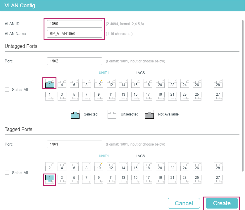
1)Go to L2 FEATURES > VLAN > 802.1Q VLAN to create VLAN 100, VLAN 200 and VLAN 1050. Configure the egress rule of port 1/0/2 in VLAN 100 and VLAN 200 as Tagged, and in VLAN 1050 as Untagged; Configure the egress rule of port 1/0/1 in VLAN 1050 as Tagged.
Figure 4-2 Create VLAN 100
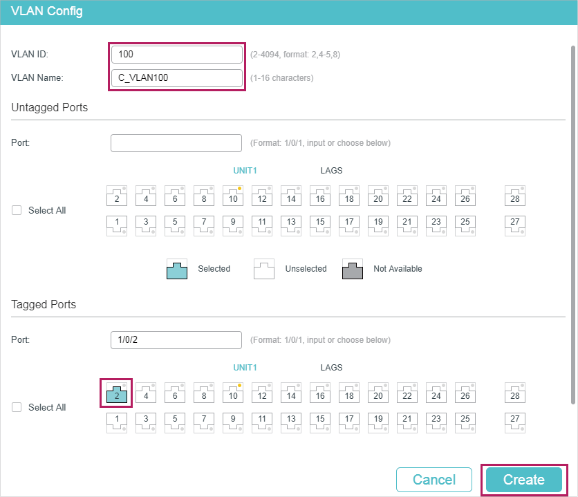
Figure 4-3 Create VLAN 200
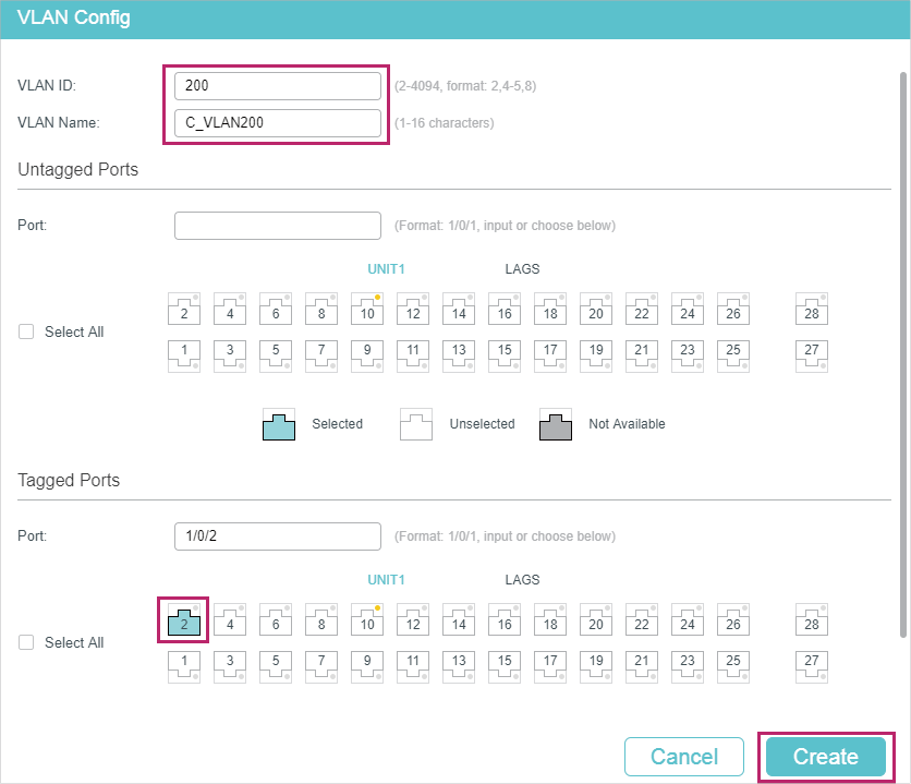
Figure 4-4 Create VLAN 1050
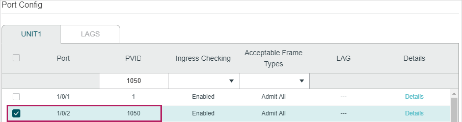
2)Go to L2 FEATURES > VLAN > Port Config to set the PVID as 1050 for port 1/0/2 and leave the default vaule 1 for port 1/0/1.
Figure 4-5 Configuring PVID
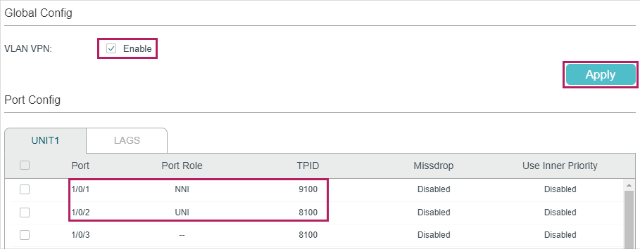
3)Go to L2 FEATURES > VLAN > VLAN VPN > VPN Config, enable VLAN VPN globally; set port 1/0/1 as NNI port and port /1/0/2 as UNI port. Specify the TPID of port 1/0/1 as 9100.
Figure 4-6 Enabling VLAN VPN Globally and Configuring the Ports
4)Click  to save the settings.
Configuring Switch 3:
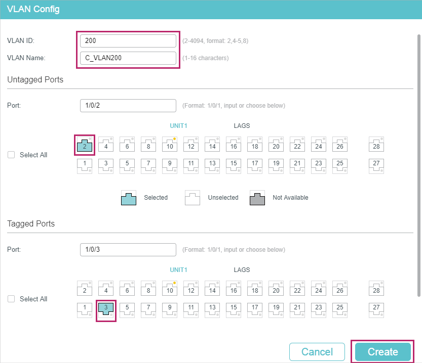
1)Go to L2 FEATURES > VLAN > 802.1Q VLAN to create VLAN 100 and VLAN 200. Configure the egress rules of port 1/0/1 in VLAN 100 as Untagged; egress rules of port 1/0/2 in VLAN 200 as Untagged; egress rule of port 1/0/3 in VLAN 100 and VLAN 200 as Tagged.
Figure 4-7 Creating VLAN 100
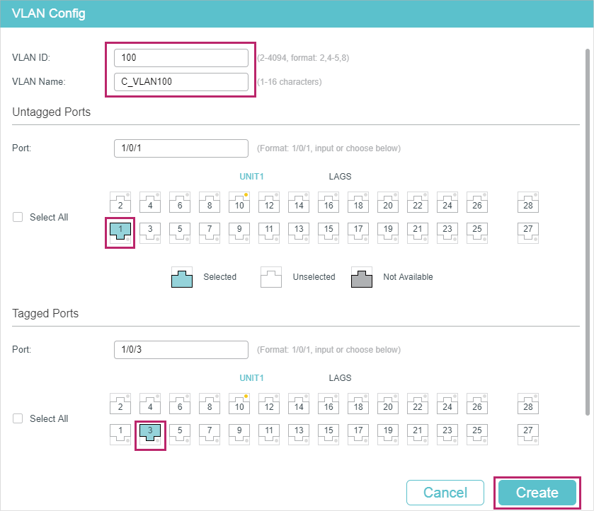
Figure 4-8 Creating VLAN 200
2)Go to L2 FEATURES > VLAN > Port Config to set the PVID as 100 for port 1/0/1 and 200 for port 1/0/2.
Figure 4-9 Configuring PVID
3)Click to save the settings.
4.1.4Using the CLI
The configurations of Switch 1 and Switch 2 are similar. The following introductions take Switch 1 as an example.
1)Create VLAN 1050, VLAN 100 and VLAN 200.
Switch_1#configure
Switch_1(config)#vlan 1050
Switch_1(config-vlan)#name SP_VLAN
Switch_1(config-vlan)#exit
Switch_1(config)#vlan 100
Switch_1(config-vlan)#name C_VLAN100
Switch_1(config-vlan)#exit
Switch_1(config)#vlan 200
Switch_1(config-vlan)#name C_VLAN200
Switch_1(config-vlan)#exit
2)Add port 1/0/1 to VLAN 1050 as tagged port, modify PVID as 1050, set the port as NNI port and specify the TPID as 9100.
Switch_1(config)#interface gigabitEthernet 1/0/1
Switch_1(config-if)#switchport general allowed vlan 1050 tagged
Switch_1(config-if)#switchport pvid1050
Switch_1(config-if)#switchport dot1q-tunnel mode nni
Switch_1(config-if)#switchport dot1q-tunnel tpid 9100
Switch_1(config-if)#exit
3)Add port 1/0/2 to VLAN 1050 as untagged port, and add it to VLAN 100 and VLAN 200 as tagged port. Modify PVID of the port as 1050. Set the port as the UNI port.
Switch_1(config)#interface gigabitEthernet 1/0/2
Switch_1(config-if)#switchport general allowed vlan 1050 untagged
Switch_1(config-if)#switchport general allowed vlan 100,200 tagged
Switch_1(config-if)#switchport pvid 1050
Switch_1(config-if)#switchport dot1q-tunnel mode uni
Switch_1(config-if)#exit
4)Enable VLAN VPN globally
Switch_1(config)#dot1q-tunnel
Switch_1(config)#end
Switch_1#copy running-config startup-config
Configuring Switch 3
1)Create VLAN 100 and VLAN 200.
Switch_3#configure
Switch_3(config)#vlan 100
Switch_3(config-vlan)#name C_VLAN100
Switch_3(config-vlan)#exit
Switch_3(config)#vlan 200
Switch_3(config-vlan)#name C_VLAN200
Switch_3(config-vlan)#exit
2)Add port 1/0/1 to VLAN 100 and port 1/0/2 to VLAN 200 as untagged ports; add port 1/0/3 to VLAN 100 and VLAN 200 as tagged ports. Configure the PVID as 100 for port 1/0/1 and 200 for port 1/0/2.
Switch_3(config)#interface gigabitEthernet 1/0/1
Switch_3(config-if)#switchport general allowed vlan 100 untagged
Switch_3(config-if)#switchport pvid 100
Switch_3(config-if)#exit
Switch_3(config)#interface gigabitEthernet 1/0/2
Switch_3(config-if)#switchport general allowed vlan 200 untagged
Switch_3(config-if)#switchport pvid 200
Switch_3(config-if)#exit
Switch_3(config)#interface gigabitEthernet 1/0/3
Switch_3(config-if)#switchport general allowed vlan 100,200 tagged
Switch_3(config-if)#end
Switch_3#copy running-config startup-config
Verify the VLAN VPN Configurations on Switch 1
Verify the configurations of global VLAN VPN:
Switch_3#show dot1q-tunnel
VLAN VPN Mode: Enabled
Mapping Mode: Disabled
Verify the configurations of VPN up-link port and VPN port:
Switch_3#show dot1q-tunnel interface
Port Type Tpid Use Inner Priority LAG
------- ------- ------- ----------------- ---
Gi1/0/1 NNI 0x9100 Disable N/A
Gi1/0/2 UNI 0x8100 Enable N/A
Gi1/0/3 NONE 0x8100 Disable N/A
Gi1/0/4 NONE 0x8100 Disable N/A
...
Verify the port configuration:
Switch_3#show interface switchport gigabitEthernet 1/0/1
Port Gi1/0/1:
PVID: 1050
Acceptable frame type: All
Ingress Checking: Enable
Member in LAG: N/A
Link Type: General
Member in VLAN:
Vlan Name Egress-rule
---- ----------- -----------
1 System-VLAN Untagged
1050 SP_VLAN Tagged
Switch_3#show interface switchport gigabitEthernet 1/0/2
Port Gi1/0/2:
PVID: 1050
Acceptable frame type: All
Ingress Checking: Enable
Member in LAG: N/A
Link Type: General
Member in VLAN:
Vlan Name Egress-rule
---- ----------- -----------
1 System-VLAN Untagged
100 C_VLAN100 Tagged
200 C_VLAN200 Tagged
1050 SP_VLAN Untagged
4.2Example for Flexible VLAN VPN
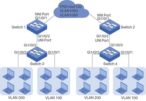
4.2.1Network Requirements
A company has two stations, and the computers belong to VLAN 100 and VLAN 200 respectively. The ISP VLAN is VLAN 1050 and VLAN 1060, and the TPID adopted by the ISP network is 0x9100.
The two stations need to communicate with each other through the ISP network. And it is required that the traffic from VLAN 100 should be transmitted in VLAN 1050, while the traffic from VLAN 200 should be transmitted in VLAN 1060.
Figure 4-10 Network Topology
4.2.2Configuration Scheme
To meet the requirement that all the traffic from VLAN 100 and VLAN 200 need to be transmitted through different ISP VLANs, users can configure flexible VLAN VPN on Switch 1 and Switch 2 to map VLAN 100 to VLAN 1050 and VLAN 200 to VLAN 1060, so packets from VLAN 100 and VLAN 200 will be transmitted through VLAN 1050 and VLAN 1060 respectively.
Here we only introduce the configuration scheme on switch 1 and switch 3, for the configurations on switch 2 are the same as that on switch 1, and the configurations on switch 4 are the same as that on switch 3.
1)Configure 802.1Q VLAN on switch 1. The parameters are shown below:
|
VLAN 100 |
VLAN 200 |
VLAN 1050 |
VLAN 1060 |
PVID |
|
|
Port 1/0/1 |
- |
- |
Tagged |
Tagged |
1 |
|
Port 1/0/2 |
Tagged |
Tagged |
Untagged |
Untagged |
1050 |
2)Configure 802.1Q VLAN on switch 3. The parameters are shown below:
|
VLAN 100 |
VLAN 200 |
PVID |
|
|
Port 1/0/1 |
- |
Untagged |
100 |
|
Port 1/0/2 |
Untagged |
- |
200 |
|
Port 1/0/3 |
Tagged |
Tagged |
1 |
3)Configure VLAN VPN on switch 1. Set port 1/0/1 as NNI port and port 1/0/2 as UNI port; configure the TPID as 0x9100; map VLAN 100 to VLAN 1050 and VLAN 200 to VLAN 1060.
Demonstrated with T2600G-28TS, this chapter provides configuration procedures in two ways: using the GUI and using the CLI.
4.2.3Using the GUI
Configuring Switch 1:
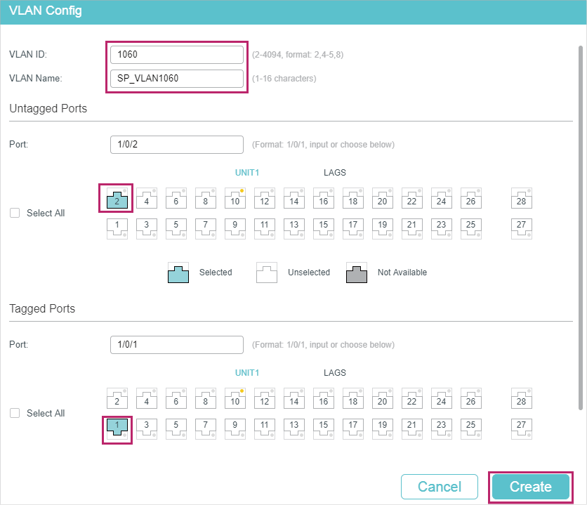
1)Go to L2 FEATURES > VLAN > 802.1Q VLAN to create VLAN 100, VLAN 200, VLAN 1050 and VLAN 1060. Configure the egress rule of port 1/0/2 in VLAN 100 and VLAN 200 as Tagged, and Untagged in VLAN 1050 and VLAN 1060; Configure the egress rule of port 1/0/1 in VLAN 1050 and VLAN 1060 as Tagged.
Figure 4-11 Create VLAN 100
Figure 4-12 Create VLAN 200
Figure 4-13 Create VLAN 1050
Figure 4-14 Create VLAN 1060
2)Go to L2 FEATURES > VLAN > Port Config to set the PVID as 1050 for port 1/0/2 and leave the default vaule 1 for port 1/0/1.
Figure 4-15 Configuring PVID
3)Go to L2 FEATURES > VLAN > VLAN VPN > VPN Config, enable VLAN VPN globally; set port 1/0/1 as NNI port and port /1/0/2 as UNI port. Specify the TPID of port 1/0/1 as 9100.
Figure 4-16 Enabling VLAN VPN Globally and Configuring the Ports
4)Go to L2 FEATURES > VLAN > VLAN VPN > VLAN Mapping, enable VLAN Mapping globally. Then configure VLAN mapping for the UNI port 1/0/2.
Figure 4-17 Mapping VLAN 100 to VLAN 1050
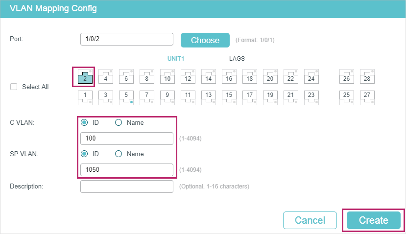
Figure 4-18 Mapping VLAN 200 to VLAN 1060
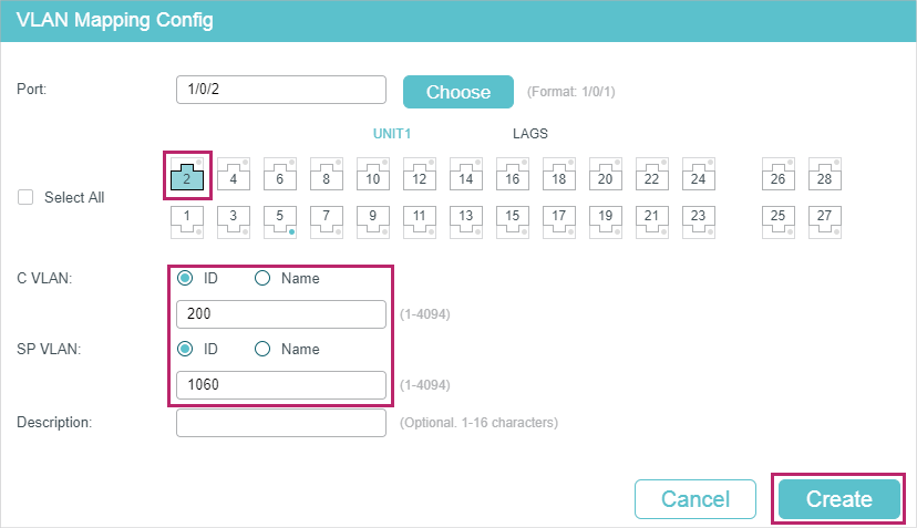
5)Click to save the settings.
Configuring Switch 3:
1)Go to L2 FEATURES > VLAN > 802.1Q VLAN to create VLAN 100 and VLAN 200. Configure the egress rules of port 1/0/1 in VLAN 100 as Untagged; egress rules of port 1/0/2 in VLAN 200 as Untagged; egress rule of port 1/0/3 in VLAN 100 and VLAN 200 as Tagged.
Figure 4-19 Creating VLAN 100
Figure 4-20 Creating VLAN 200
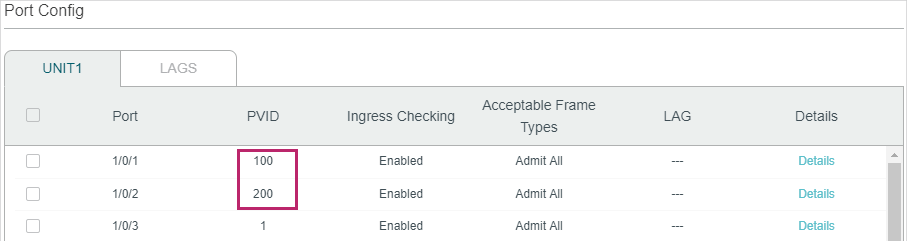
2)Go to L2 FEATURES > VLAN > Port Config to set the PVID as 100 for port 1/0/1 and 200 for port 1/0/2.
Figure 4-21 Configuring PVID
3)Click to save the settings.
4.2.4Using the CLI
Configuring Switch 1
1)Create VLAN 100, VLAN 200, VLAN 1050 and VLAN 1060.
Switch_1#configure
Switch_1(config)#vlan 1050
Switch_1(config-vlan)#name SP_VLAN1050
Switch_1(config-vlan)#exit
Switch_1(config)#vlan 1060
Switch_1(config-vlan)#name SP_VLAN1060
Switch_1(config-vlan)#exit
Switch_1(config)#vlan 100
Switch_1(config-vlan)#name C_VLAN100
Switch_1(config-vlan)#exit
Switch_1(config)#vlan 200
Switch_1(config-vlan)#name C_VLAN200
Switch_1(config-vlan)#exit
2)Add port 1/0/1 to VLAN 1050 and VLAN 1060 as tagged port, modify PVID as 1050, set the port as NNI port and specify the TPID as 9100.
Switch_1(config)#interface gigabitEthernet 1/0/1
Switch_1(config-if)#switchport general allowed vlan 1050,1060 tagged
Switch_1(config-if)#switchport pvid1050
Switch_1(config-if)#switchport dot1q-tunnel mode nni
Switch_1(config-if)#switchport dot1q-tunnel tpid 9100
Switch_1(config-if)#exit
3)Add port 1/0/2 to VLAN 1050 and VLAN 1060 as untagged port, and add it to VLAN 100 and VLAN 200 as tagged port. Modify the PVID as 1050. Set the port as the UNI port.
Switch_1(config)#interface gigabitEthernet 1/0/2
Switch_1(config-if)#switchport general allowed vlan 1050,1060 untagged
Switch_1(config-if)#switchport general allowed vlan 100,200 tagged
Switch_1(config-if)#switchport pvid 1050
Switch_1(config-if)#switchport dot1q-tunnel mode uni
Switch_1(config-if)#exit
4)Enable VLAN mapping. Map VLAN 100 to VLAN 1050 and VLAN 200 to VLAN 1060 for port 1/0/2.
Switch_1(config)#dot1q-tunnel mapping
Switch_1(config)#interface gigabitEthernet 1/0/2
Switch_1(config-if)#switchport dot1q-tunnel mapping 100 1050 mapping
Switch_1(config-if)#switchport dot1q-tunnel mapping 200 1060 mapping
Switch_1(config-if)#exit
5)Enable VLAN VPN globally
Switch_1(config)#dot1q-tunnel
Switch_1(config)#end
Switch_1#copy running-config startup-config
Configuring Switch 3
1)Create VLAN 100 and VLAN 200.
Switch_3#configure
Switch_3(config)#vlan 100
Switch_3(config-vlan)#name C_VLAN100
Switch_3(config-vlan)#exit
Switch_3(config)#vlan 200
Switch_3(config-vlan)#name C_VLAN200
Switch_3(config-vlan)#exit
2)Add port 1/0/1 to VLAN 100 and port 1/0/2 to VLAN 200 as untagged ports; add port 1/0/3 to VLAN 100 and VLAN 200 as tagged ports. Configure the PVID as 100 for port 1/0/1 and 200 for port 1/0/2.
Switch_3(config)#interface gigabitEthernet 1/0/1
Switch_3(config-if)#switchport general allowed vlan 100 untagged
Switch_3(config-if)#switchport pvid 100
Switch_3(config-if)#exit
Switch_3(config)#interface gigabitEthernet 1/0/2
Switch_3(config-if)#switchport general allowed vlan 200 untagged
Switch_3(config-if)#switchport pvid 200
Switch_3(config-if)#exit
Switch_3(config)#interface gigabitEthernet 1/0/3
Switch_3(config-if)#switchport general allowed vlan 100,200 tagged
Switch_3(config-if)#end
Switch_3#copy running-config startup-config
Default settings of VLAN VPN are listed in the following table.
Table 5-1Default Settings of VLAN VPN
|
Parameter |
Default Setting |
|
Global VLAN VPN |
Disabled |
|
Port Role |
None |
|
Global TPID |
0x8100 |
|
Missdrop |
Disabled |
|
Use Inner Priority |
Disabled |
|
VLAN Mapping |
Disabled |