Configuring the Network (CPE and WBS)
CHAPTERS
4. Configure the Forwarding Feature
5. Configure the Security Feature
8. Configure Bandwidth Control
|
|
This guide applies to: CPE210(UN) 1.0, CPE210(UN) 2.0, CPE210(UN) 3.0, CPE210(EU) 3.0, CPE220(UN) 1.0, CPE220(UN) 2.0, CPE220(UN) 3.0, CPE510(UN) 1.0, CPE510(UN) 2.0, CPE510(UN) 3.0, CPE520(UN) 1.0, CPE520(UN) 2.0, CPE610(UN) 1.0, WBS210(UN) 1.0, WBS210(UN) 2.0, WBS510(UN) 1.0, WBS510(UN) 2.0. |

This guide introduces how to configure wireless network using the CPE/WBS products:
1. Configure WAN Parameters
2. Configure LAN Parameters
3. Configure Management VLAN
4. Configure the Forwarding Feature
5. Configure the Security Feature
6. Configure Access Control
7. Configure Static Routing
8. Configure Bandwidth Control
9. Configure IP & MAC Binding
The following parts detailedly introduces these features.
|
|
Note: WAN submenu is only available in AP Router mode and AP client Router (WISP client) mode. |

WAN submenu is used to create the WAN connection and configure the related advanced parameters.
Go to the Network page. In the WAN section, configure the WAN parameters of the device.
Figure 1-1 Configuring the WAN Parameters
Follow the steps below to configure the WAN parameters:
1)Select the connection type according to your need. The device supports five types: Static, Dynamic, PPPoE, L2TP, and PPTP.
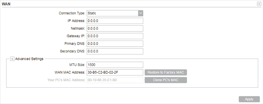
»Static
This connection type uses a permanent, fixed (static) IP address that is assigned by your ISP. In this type, you should fill in the IP address, Netmask, Gateway IP, and DNS IP address manually, which are assigned by your ISP.
Figure 1-2 Static Type
|
IP address |
Enter the IP address provided by your ISP. |
|
Netmask |
Enter the netmask provided by your ISP. Normally use 255.255.255.0. |
|
Gateway IP |
Enter the gateway IP address provided by your ISP. |
|
Primary DNS |
Enter the DNS IP address provided by your ISP. |
|
Secondary DNS |
Enter alternative DNS IP address if your ISP provides it. |
|
MTU Size |
The normal MTU (Maximum Transmission Unit) value for most Ethernet networks is 1500 Bytes. For some ISPs you need to modify the MTU. But this is rarely required, and should not be done unless you are sure it is necessary for your ISP connection. |
|
WAN MAC Address |
Specify the MAC address of WAN interface. This field displays the current MAC address of the WAN port. If your ISP requires that you register the MAC address, enter the correct MAC address into this field. The format for the MAC Address is XX-XX-XX-XX-XX-XX (X is any hexadecimal digit). Click Restore Factory MAC to restore the MAC address of WAN port to the factory default value. |
|
Your PC's MAC Address |
Displays the MAC address of the PC that is managing the router. Some ISPs require that you should register the MAC address of your PC. If the MAC address is required, you can click Clone PC’s MAC to set the WAN MAC address the same as your management PC’s MAC address. |
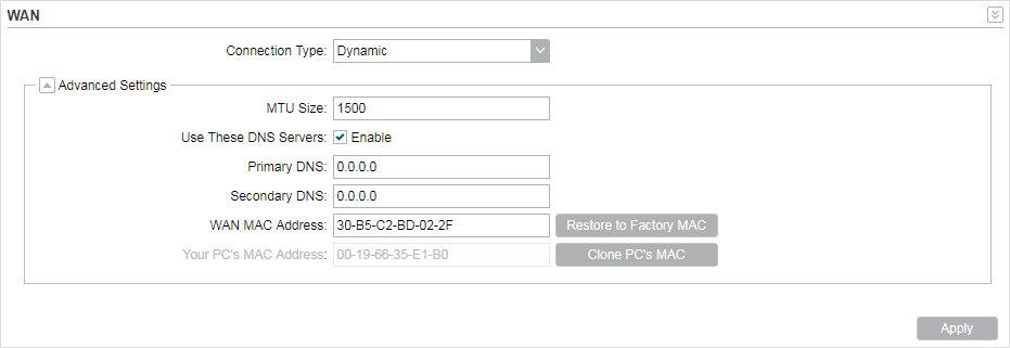
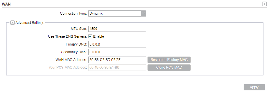
»Dynamic
For this connection, your ISP uses a DHCP server to assign your router an IP address for connecting to the internet. You don’t need to configure any parameters.
Figure 1-3 Dynamic Mode
|
MTU Size |
Specify the MTU size. The normal MTU (Maximum Transmission Unit) value for most Ethernet networks is 1500 Bytes. For some ISPs you need to modify the MTU. But this is rarely required, and should not be done unless you are sure it is necessary for your ISP connection. |
|
Use These DNS Servers |
If your ISP gives you one or two DNS IP addresses, select Use These DNS Servers and enter the Primary DNS and Secondary DNS into the correct fields. Otherwise, the DNS servers will be assigned from ISP dynamically. |
|
Primary DNS |
Enter the DNS IP address provided by your ISP. |
|
Secondary DNS |
Enter another DNS IP address provided by your ISP. |
|
WAN MAC Address |
Specify the WAN MAC address. This field displays the current MAC address of the WAN port. If your ISP binds the MAC address of your previous computer/router, enter the correct MAC address into this field. The format for the MAC Address is XX-XX-XX-XX-XX-XX (X is any hexadecimal digit). Click Restore Factory MAC to restore the MAC address of WAN port to the factory default value. |
|
Your PC’s MAC Address |
Displays the MAC address of the PC that is managing the router. Some ISPs require that you should register the MAC address of your PC. If the MAC address is required, you can click Clone PC’s MAC to set the WAN MAC address the same as your management PC’s MAC address. |
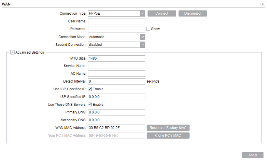
»PPPoE
If your ISP delivers internet through phone line and provides you with username and password, you should choose this type. Under this condition, you should fill in both User Name and Password that the ISP supplied. Note that these fields are case-sensitive.
Figure 1-4 PPPoE Type
|
User Name |
Enter the User Name that is provided by your ISP. |
|
Password |
Enter the Password that is provided by your ISP. |
|
Connection Mode |
Select the Connection Mode. On Demand You can configure the device to disconnect your internet connection after a specified period of inactivity (Idle Time). If your internet connection has been terminated due to inactivity, Connection on Demand enables the device to automatically re-establish your connection when you attempt to access the internet again. The default Idle Time is 15 minutes. If your internet connection is expected to remain active all the time, enter 0 in the Idle Time field. Users those pay by time for their internet access can choose this mode to save their internet-access fee.
Automatic Connect automatically after the device is disconnected. Users those are charged a flat monthly fee can choose this mode. Time-based You can configure the device to make it connect or disconnect based on time. Enter the start time in From (HH:MM) for connecting and end time in To (HH:MM) for disconnecting. Users those need to control the time period of internet access can choose this mode.
Manual You can configure the device to make it connect or disconnect manually. After a specified period of inactivity (Idle Time), the device will disconnect your internet connection, and you must click Connect manually to access the internet again. If your internet connection is expected to remain active all the times, enter 0 in the Idle Time field. Otherwise, enter the desired Idle Time in minutes you wish to use. Users charged by time for their internet access can choose this mode to save their internet-access fee.
|
|
Second Connection |
If your ISP provides an extra Connection type such as Dynamic/Static IP to connect to a local area network, you can activate this secondary connection. Disable: The Secondary Connection is disabled by default, so there is PPPoE connection only. This is recommended. Dynamic IP: Use dynamic IP address to connect to the local area network provided by ISP. Static IP: Use static IP address to connect to the local area network provided by ISP. |
|
MTU Size |
Specify the MTU size. The default MTU (Maximum Transmission Unit) size is 1480 bytes, which is usually appropriate. For some ISPs, you need modify the MTU. This should not be done unless your ISP told you to. |
|
Service Name |
Specify the Service Name provided by your ISP. Please keep it empty if your ISP doesn't provide the name. |
|
AC Name |
Specify the AC Name provided by your ISP. Please keep it empty if your ISP doesn't provide the name. |
|
Detect Internal |
Specify the Detect Interval. The default value is 0. You can input the value between 0 and 120. The device will detect Access Concentrator online every interval seconds. If the value is 0, it means not detecting. |
|
Use ISP-specified IP |
If your service provider provides you with an IP address along with the user name and password, Enable "Use ISP-specified IP" and enter the IP address. |
|
Use These DNS Servers |
If the ISP provides a DNS server IP address for you, Enable Use These DNS Server, and fill the Primary DNS and Secondary DNS fields below. Otherwise, the DNS servers will obtain automatically from ISP. |
|
WAN MAC Address |
Specify the WAN MAC address. This field displays the current MAC address of the WAN port. If your ISP binds the MAC address of your previous computer/router, enter the correct MAC address into this field. The format for the MAC Address is XX-XX-XX-XX-XX-XX (X is any hexadecimal digit). Click Restore Factory MAC to restore the MAC address of WAN port to the factory default value. |
|
Your PC's MAC Address |
Displays the MAC address of the PC that is managing the router. You can click Clone PC’s MAC to set the WAN MAC address the same as your management PC’s MAC address. |
|
Restore to Factory MAC |
Click this button to restore the WAN MAC address as factory MAC address. |
|
Clone PC's MAC |
Click this button to set the WAN MAC address as PC’s MAC address. |


»L2TP/PPTP
If your ISP supplies internet access through L2TP or PPTP, it will provide the following parameters. The configurations of L2TP and PPTP are the same, and the following introduction takes L2TP as an example.
Figure 1-5 L2TP/PPTP Type
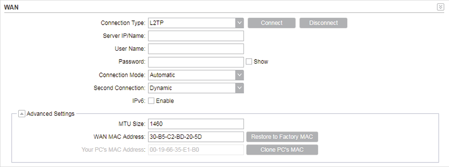
Specify the parameters below and click Connect:
|
Server IP/Name |
Enter the server IP address or the domain name provided by your ISP. |
|
User Name |
Enter the User Name provided by your ISP. This field is case-sensitive. |
|
Password |
Enter the Password provided by your ISP. This field is case-sensitive. |
|
Connection Mode |
Select the Connection Mode. On Demand You can configure the device to disconnect your internet connection after a specified period of inactivity (Idle Time). If your internet connection has been terminated due to inactivity, Connection on Demand enables the device to automatically re-establish your connection when you attempt to access the internet again. The default Idle Time is 15 minutes. If your internet connection is expected to remain active all the time, enter 0 in the Idle Time field. Users those pay by time for their internet access can choose this mode to save their internet-access fee.
Automatic Connect automatically after the device is disconnected. Users those are charged a flat monthly fee can choose this mode. Manual You can configure the device to make it connect or disconnect manually. After a specified period of inactivity (Idle Time), the device will disconnect your internet connection, and you must click Connect manually to access the internet again. If your internet connection is expected to remain active all the times, enter 0 in the Idle Time field. Otherwise, enter the desired Idle Time in minutes you wish to use. Users charged by time for their internet access can choose this mode to save their internet-access fee.
|
|
Second Connection |
If your ISP provides a Connection type such as Dynamic/Static IP to connect to a local area network, you can activate this secondary connection. Dynamic IP: Use dynamic IP address to connect to the local area network provided by ISP. Static IP: Use static IP address to connect to the local area network provided by ISP. |
|
MTU Size |
Specify the MTU size. The normal MTU (Maximum Transmission Unit) value for most Ethernet networks is 1500 Bytes. For some ISPs you need to modify the MTU. But this is rarely required, and should not be done unless you are sure it is necessary for your ISP connection. |
|
WAN MAC Address |
Specify the WAN MAC address. This field displays the current MAC address of the WAN port. If your ISP requires that you register the MAC address, enter the correct MAC address into this field. The format for the MAC Address is XX-XX-XX-XX-XX-XX (X is any hexadecimal digit). Click Restore Factory MAC to restore the MAC address of WAN port to the factory default value. |
|
Your PC's MAC Address |
Displays the MAC address of the PC that is managing the router. Some ISPs require that you should register the MAC address of your PC. If the MAC address is required, you can click Clone PC’s MAC to set the WAN MAC address the same as your management PC’s MAC. |
2)Click Apply, then click Save.
LAN submenu is used to configure the LAN parameters for the device and the clients.
2.1Access Point/Client/Repeater/Bridge Mode
Go to the Network page. In the LAN section, configure the following parameters.
Figure 2-1 LAN Parameters
Follow the steps below to configure the LAN parameters:
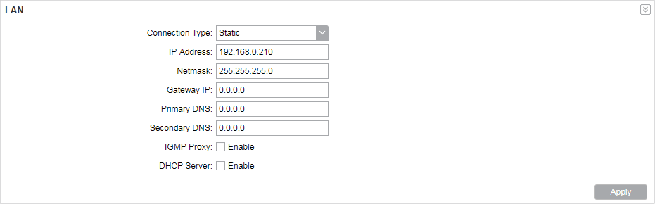
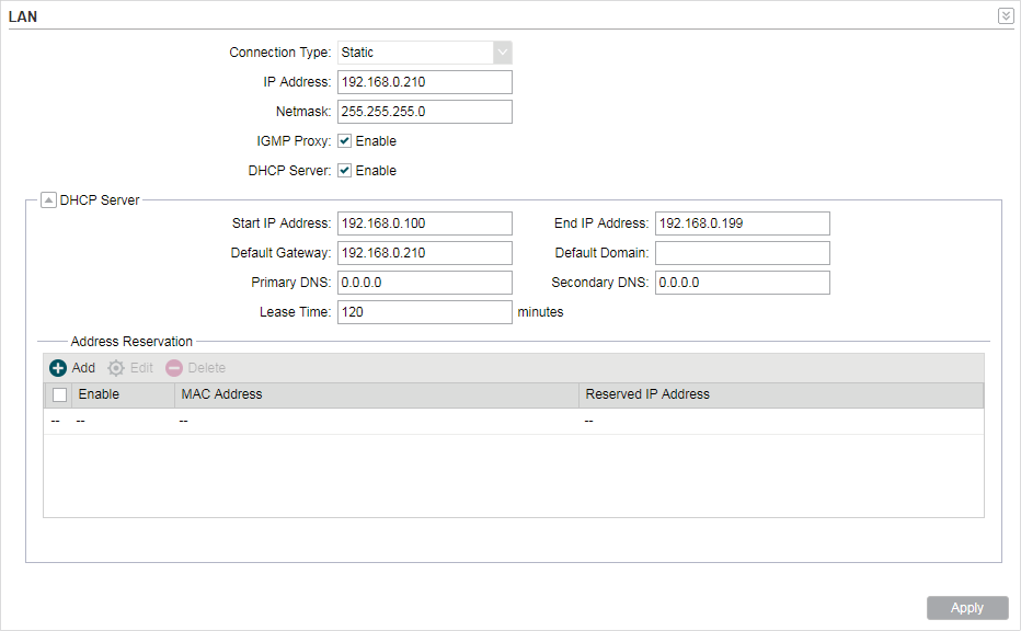
1)Select the connection type according to your need. The device supports two types: Static and Dynamic.
»Static
Figure 2-2 Static Type
|
IP address |
Enter the LAN IP address of your device. By default, it is 192.168.0.254. |
|
Netmask |
Enter the Netmask provided by your ISP. Normally use 255.255.255.0. |
|
Gateway IP |
Enter the gateway IP address for your device. |
|
Primary DNS |
Enter the primary DNS IP address provided by your ISP. Please consult your ISP if you don’t know the DNS value. The factory default setting is 0.0.0.0. |
|
Secondary DNS |
Enter the secondary DNS IP address of alternative DNS server if your ISP two DNS servers. The factory default setting is 0.0.0.0. |
|
MTU Size |
Specify the MTU size. The normal MTU (Maximum Transmission Unit) value for most Ethernet networks is 1500 Bytes. For some ISPs you need to modify the MTU. But this is rarely required, and should not be done unless you are sure it is necessary for your ISP connection. |
|
IGMP Proxy |
Enable or disable IGMP (Internet Group Management Protocol) Proxy. IGMP proxy is used to process the multicast stream in the netwok. It normally works for IPTV service. |
|
DHCP Server |
Enable or disable the DHCP server function. With this function enabled, the build-in DHCP server will assign IP address to the clients connected to the device. |
|
Start IP Address |
Specify the first IP address of the IP address pool. By default, it is 192.168.0.100. |
|
End IP Address |
Specify the last IP address of the IP address pool. By default, it is 192.168.0.199. |
|
Default Gateway |
Specify the gateway IP address for the LAN network. By default, it is 192.168.0.254. |
|
Default Domain |
(Optional) Specify the domain name for the DHCP server. |
|
Primary DNS |
Enter the DNS IP address for the LAN. By default,it is 0.0.0.0. |
|
Secondary DNS |
Enter the IP address of alternative DNS server if there are two DNS servers. By default, it is 0.0.0.0. |
|
Lease Time |
Enter the amount time of the leased IP address assigned by the DHCP server. When the time expires, the clients will request to renew the lease automatically. |
|
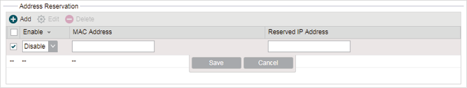
Address Reservation |
Enable Address Reservation and you can specify a reserved IP address for a PC on the local area network, so the PC will always obtain the same IP address each time when it starts up. Reserved IP addresses could be assigned to servers that require permanent IP settings.
To configure Address Reservation: Click Add, specify the MAC address and the IP address. Enable this entry, then click Save. |
|
IPv6 |
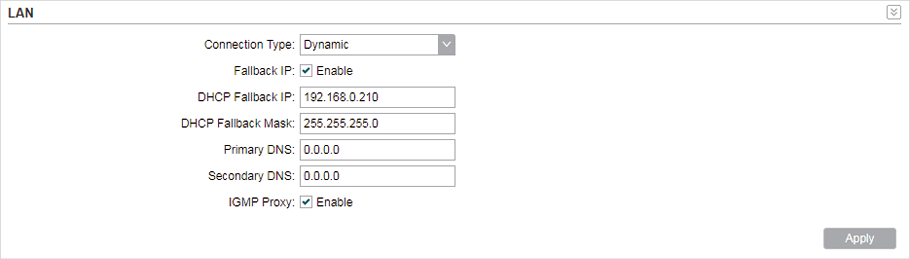
»Dynamic
Figure 2-3 Dynamic Type
|
Fallback IP |
Enable or disable the Fallback IP. When the device doesn’t find DHCP server, it will use the fallback IP as the LAN IP address. |
|
DHCP Fallback IP |
Specify the fallback IP for the device. By default, it is 192.168.0.254. |
|
DHCP Fallback Mask |
Specify the fallback netmask for the device. |
|
Primary DNS |
Enter the DNS IP address for the LAN. By default, it is 0.0.0.0. |
|
Secondary DNS |
Enter the IP address of alternative DNS server if there are two DNS servers. By default, it is 0.0.0.0. |
|
IGMP Proxy |
Enable or disable IGMP (Internet Group Management Protocol) Proxy. IGMP proxy is used to process the multicast stream in the network. It normally works for IPTV service. |
2)Click Apply, then click Save.
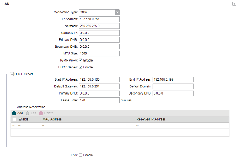
2.2AP Router/AP Client Router Mode
Go to the Network page. In the LAN section, configure the following parameters.
Figure 2-4 LAN Settings
1)For LAN connection type, the device only supports Static.
|
IP address |
Enter the LAN IP address of your device. By default, it is 192.168.0.254. |
|
Netmask |
Enter the Netmask provided by your ISP. Normally use 255.255.255.0. |
|
IGMP Proxy |
Enable or disable IGMP (Internet Group Management Protocol) Proxy. IGMP proxy is used to process the multicast stream in the netwok. It normally works for IPTV service. |
|
DHCP Server |
Enable or disable the DHCP server function. With this function enabled, the build-in DHCP server will assign IP address to the clients connected to the device. |
|
Start IP Address |
Specify the first IP address of the IP address pool. By default, it is 192.168.0.100. |
|
End IP Address |
Specify the last IP address of the IP address pool. By default, it is 192.168.0.199. |
|
Default Gateway |
Specify the gateway IP address for the LAN network. By default, it is 192.168.0.254. |
|
Default Domain |
(Optional) Specify the domain name for the DHCP server. |
|
Primary DNS |
Enter the DNS IP address for the LAN. By default,it is 0.0.0.0. |
|
Secondary DNS |
Enter the IP address of alternative DNS server if there are two DNS servers. By default, it is 0.0.0.0. |
|
Lease Time |
Enter the amount time of the leased IP address assigned by the DHCP server. When the time expires, the clients will request to renew the lease automatically. |
|
Address Reservation |
Enable Address Reservation and you can specify a reserved IP address for a PC on the local area network, so the PC will always obtain the same IP address each time when it starts up. Reserved IP addresses could be assigned to servers that require permanent IP settings.
To configure Address Reservation: Click Add, specify the MAC address and the IP address. Enable this entry, then click Save. |
2)Click Apply, then click Save.
Management VLAN provides a safer way for you to manage the device. With Management VLAN enabled, only the hosts in the management VLAN can manage the device. Since most hosts cannot process VLAN tags, connect the management host to the network via a switch, and set up correct VLAN settings to ensure the communication between the host and the device in the management VLAN.
Go to the Network page. In the Management VLAN Interfaces section, enable the Management VLAN function, specify VLAN ID and click Apply. Then click Save.
Figure 3-1 Configuring Management VLAN

|
Management VLAN |
Enable or disable the Management VLAN function. By default, it is disabled. |
|
VLAN ID |
Specify the Management VLAN ID. The valid values are from 2 to 4094. |
4Configure the Forwarding Feature
|
|
Note: Forwarding submenu is only available in AP Router mode and AP client Router (WISP client) mode. |
The IP address used on the internet is public IP address, while IP address used on local area network is private IP address. The hosts using private IP addresses cannot access the internet directly and vice versa.
The hosts using private IP addresses visit internet through NAT (Network Address Translation) technology. NAT can transfer private IP addresses into public IP addresses to realize the communication from internal hosts to external hosts.
If the hosts on the internet want to visit the hosts on local area network, the forwarding function should be used, including DMZ, Virtual server, Port triggering and UPnP.
Go to the Network page. In the Forwarding section, configure the following parameters and click Apply. Then click Save.
Figure 4-1 Configuring Forwarding Feature

|
DMZ |
Enable or disable the DMZ function. DMZ (Demilitarized Zone) specifically allows one computer/device behind NAT to become “demilitarized”, so all packets from the external network are forwarded to this computer/device. The demilitarized host is exposed to the wide area network, which can realize the unlimited bidirectional communication between internal hosts and external hosts. |
|
DMZ IP |
Specify the IP address of the local host network device. The DMZ host device will be completely exposed to the external network. Any PC that was used for a DMZ must have a static or reserved IP Address because its IP Address may change when using the DHCP function. |
|
ALG |
Select the type of ALG to enable the corresponding feature. Common NAT only translates the address of packets at network layer and the port number at transport layer but cannot deal with the packets with embedded source/destination information in the application layer. Application layer gateway (ALG) can deal with protocols with embedded source/destination information in the application payload. Some protocols such as FTP, TFTP, H323 and RTSP require ALG (Application Layer Gateway) support to pass through NAT. FTP ALG: Allows FTP clients and servers to transfer data across NAT. TFTP ALG: Allows TFTP clients and servers to transfer data across NAT. H323 ALG: Allows Microsoft NetMeeting clients to communicate across NAT. RTSP ALG: Allows some media player clients to communicate with some streaming media servers across NAT. |
|
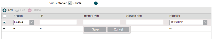
Virtual Server |
Enable or disable Virtual Server. Virtual servers can be used for setting up public services on your local area network, such as DNS, Email and FTP. A virtual server is defined as a service port, and all requests from the internet to this service port will be redirected to the LAN server. Virtual Server function not only makes the users from internet visit the local area network, but also keeps network security within the intranet as other services are still invisible from internet. The LAN server must have a static or reserved IP Address because its IP Address may change when using the DHCP function.
To configure Virtual Server: Click Add, specify the following parameters and Enable the entry. Click Save. IP: Enter the IP Address of the PC providing the service application. Internal Port: Enter the Internal Port number of the PC running the service application. You can leave it blank if the Internal Port is the same as the Service Port, or enter a specific port number. Service Port: Enter the numbers of external Service Port. You can type a service port or a range of service ports (the format is XXX – YYY, XXX is the start port, YYY is the end port). Internet users send request to the port for services. Protocol: Choose the one of the protocols used for this application: TCP, UDP, or TCP/UDP. |
|
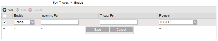
Port Trigger |
Enable or disable port trigger. Due to the existence of the firewall, some applications such as online games, video conferences, VoIPs and P2P downloads need the device to configure the forwarding to work properly, and these applications require multiple ports connection, for single-port virtual server cannot meet the demand. Port trigger function comes at this time. When an application initiates a connection to the trigger port, all the incoming ports will open for subsequent connections.
To configure port trigger: Click Add, specify the following parameters and Enable the entry. Click Save. Incoming Port: Enter the incoming port for incoming traffic. The port or port range is used by the remote system when it responds to the outgoing request. A response to one of these ports will be forwarded to the PC that triggered this rule. You can input at most 5 groups of ports (or port section). Every group of ports must be set apart with “,”. For example, 2000-2038, 2050-2051, 2085, 3010-3030. Trigger Port: Enter the trigger port for outgoing traffic. An outgoing connection using this port will “Trigger” this rule. Protocol: Choose the one of the protocols used for this application: TCP, UDP, or TCP/UDP. |
|
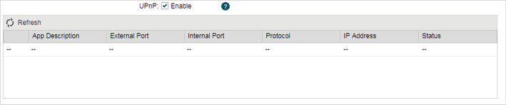
UPnP |
Enable or disable UPnP. If you use applications such as multiplayer gaming, peer-to-peer connections, or real-time communications such as instant messaging or remote assistance (a feature in Windows XP), you should enable the UPnP function. The Universal Plug and Play (UPnP) function allows the devices, such as internet computers, to access the local host resources or devices as needed. Host in the local area network can automatically open the corresponding ports on a router, and make the application of external host access the resources of the internal host through the opened ports. Therefore, the functions limited to the NAT can work properly. Compared to virtual server and port triggering, the application of UPnP doesn’t need manual settings. It is more convenient for some applications required unfixed ports.
App Description: Displays the description provided by the application in the UPnP request. External Port: Displays the external port number that the router opened for the service application. Protocol: Displays which type of protocol is opened. Internal Port: Displays the internal service port number of the local host running the service application. IP Address: Displays the IP address of the local host which initiates the UPnP request. Status: Enabled means that port is still active. Otherwise, the port is inactive. |
5Configure the Security Feature
|
|
Note: Security submenu is only available in AP Router mode and AP client Router (WISP client) mode. |
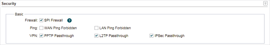
Stateful Packet Inspection (SPI) is a firewall that keeps track of the state of network connections (such as TCP streams, UDP communication) traveling across it. The firewall is programmed to distinguish legitimate packets for different types of connections. Only packets matching a known active connection will be allowed to pass through by the firewall and others will be rejected. SPI Firewall is enabled by factory default.
1)Go to the Network page. In the Security > Basic section, configure the following parameters and click Apply.
Figure 5-1 Configuring Security Feature
|
SPI Firewall |
Check the Enable box to use the SPI Firewall function. If forwarding rules are enabled at the same time, the device will give priority to meet forwarding rules. |
|
Ping |
Select and enable the ping forbidden function. WAN Ping Forbidden: Enable or disable this function. With this option enabled, the device will not reply the ping request originates from internet. By default, it is disabled. LAN Ping Forbidden: Enable or disable this function. With this option enabled, the device will not reply the ping request originates from local network. |
|
VPN |
Select and enable the VPN function. A VPN is created by establishing a virtual point-to-point connection through the use of dedicated connections, virtual tunneling protocols, or traffic encryptions. Through VPN you can access your private network over internet. A virtual private network connection across the internet is similar to a wide area network (WAN) link between sites. From a user perspective, the extended network resources are accessed in the same way as resources available within the private network. When hosts in the local area network want to visit the remote virtual private network using virtual tunneling protocols, the corresponding VPN protocol should be enabled. PPTP Passthrough: PPTP (Point-to-Point Tunneling Protocol) allows the Point-to-Point Protocol (PPP) to be tunneled through an IP (Internet Protocol) network. Check the box to allow PPTP tunnels to pass through the Device. L2TP Passthrough: L2TP (Layer Two Tunneling Protocol) is the method used to enable Point-to-Point connections via the internet on the Layer Two level. Check the box to allow L2TP tunnels to pass through the Device. IPSec Passthrough: IPSec (Internet Protocol Security) is a suite of protocols for ensuring private, secure communications over IP (Internet Protocol) networks, through the use of cryptographic security services. Check the box to allow IPSec tunnels to pass through the Device. |
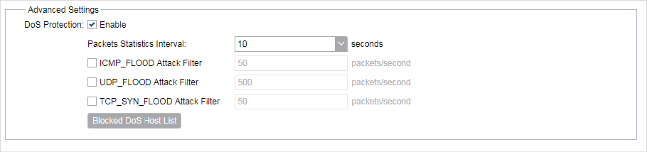
2)In the Security > Advanced Settings section, configure the following parameters and click Apply.
Figure 5-2 Configuring Advanced Settings
|
DoS Protection |
Enable the DoS Protection and specify the parameters. DoS (Denial of Service) Attack is to occupy the network bandwidth maliciously by the network attackers or the evil programs sending a lot of service requests to the Host, which incurs an abnormal service or even breakdown of the network. With DoS Protection function enabled, the device can analyze the specific fields of the IP packets and distinguish the malicious DoS attack packets. Upon detecting the packets, the device will discard the illegal packets directly and limit the transmission rate of the legal packets if the over legal packets may incur a breakdown of the network. The hosts sending these packets will be added into the Blocked DoS Host List. The device can defend a few types of DoS attack such as ICMP_FLOOD, UDP_FLOOD and TCP_SYN_FLOOD. Packets Statistics Interval: Select a value between 5 and 60 seconds from the drop-down list. The default value is 10. The value indicates the time interval of the packets statistics. The result of the statistic is used for analysis by ICMP-Flood, UDP Flood and TCP-SYN Flood. ICMP_FLOOD Attack Filter: Enter a value between 5 and 3600. The default value is 50. When the current ICMP-FLOOD Packets number is beyond the set value, the device will start up the blocking function immediately. UDP_FLOOD Attack Filter: Enter a value between 5 and 3600. The default value is 500. When the current UPD-FLOOD Packets number is beyond the set value, the device will start up the blocking function immediately. TCP_SYN_FLOOD Attack Filter: Enter a value between 5 and 3600. The default value is 50. When the current TCP-SYN-FLOOD Packets numbers is beyond the set value, the Device will start up the blocking function immediately. |
|
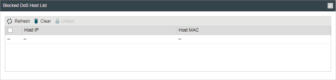
Blocked DoS Host List |
Click Blocked DoS Host List to display the blocked DoS host table including host IP and host MAC. Click Refresh to renewal the table list. Click Clear to release all the blocked hosts. If you want to release one or some of the blocked hosts, select them and Click Unlock.
|
3)Click Save.
|
|
Note: Access Control submenu is only available in AP Router mode and AP client Router (WISP client) mode. |
The function can be used to control the internet activities of hosts in the local area network. For example, the online time limit and the specified web stations to visit can be controlled by the filtering policy.
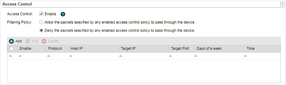
1)Go to the Network page. In the Access Control section, enable Access Control and select the Filtering Policy.
Figure 6-1 Configuring Access Control
|
Access Control |
Enable or disable Access Control. |
|
Filtering Policy |
Select the filtering policy according to your need. Allow the packets specified by any enabled access control policy to pass through the Device: The hosts listed below are allowed to access the internet under the rules. While others are forbidden to access. Deny the packets specified by any enabled access control policy to pass through the Device: The hosts listed below are forbidden to access the internet under the rules. While others are allowed to access. |
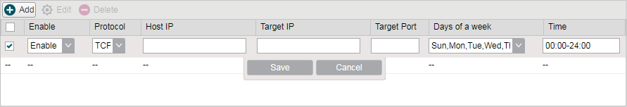
2)Click Add and create the filtering entries.
Figure 6-2 Creating Filtering Entries
|
Enable |
Enable or disable the desired entry. |
|
Protocol |
Choose one of the protocols from the drop-down list used for the target, any of IP, TCP, UDP, or ICMP. |
|
Host IP |
Enter the IP address or address range of the hosts that you need to control, for example 192.168.0.12-192.168.0.25. |
|
Target IP |
Enter the IP address or address range of the targets that you need to control, for example 192.168.3.12-192.168.3.25. |
|
Target Port |
Specify the port or port range for the target when protocol is TCP or UDP. |
|
Days of a week |
Specify the days in which the rules take effect. |
|
Time |
Enter the time rule in HH:MM-HH:MM format, the default value is 00:00-24:00. |
3)Click Save and click Apply, then click Save.
|
|
Note: Static Routing submenu is only available in AP Router mode and AP client Router (WISP client) mode. |
A static route is a pre-determined path that network information must travel to reach a specific host or network. If static route is used properly in the network, it can decrease the network overhead and improve the speed of forwarding packets.
Static routing is generally suitable for simple network environment, in which users clearly understand the topology of the network so as to set the routing information correctly. When the network topology is complicated and users are not so familiar with the topology structure, this function should be used with caution or under the guidance of the experienced administrator.
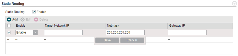
1)Go to the Network page. In the Static Routing section, click Add and specify the following parameters.
Figure 7-1 Configuring Static Routing
|
Enable |
Enable or disable the desired entry. |
|
Target Network IP |
Enter the Target Network IP, the address of the network or host to be visited. The IP address cannot be on the same network segment with the device’s WAN or LAN port. |
|
Netmask |
Specify the netmask for the desired entry. |
|
Gateway IP |
Enter the Gateway IP, the address of the gateway that allows for contact between the Device and the network or host |
2)Click Save and click Apply, then click Save.
|
|
Note: Bandwidth Control submenu is only available in AP Router mode and AP client Router (WISP client) mode. |
Bandwidth control function is used to control the internet bandwidth in the local area network. In the case of insufficient bandwidth resources, enable the function to make the device allocate reasonable bandwidth to the clients and achieve the purpose of efficient use of the existing bandwidth. Via IP bandwidth control function, you can set the upper and lower limit in the bandwidth of the computer network and guarantee a smooth sharing network.
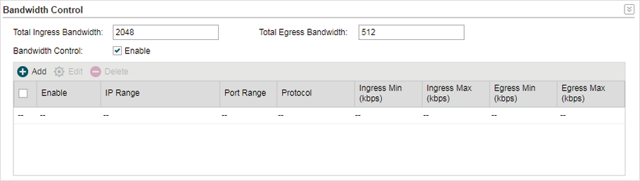
1)Go to the Network page. In the Bandwidth Control section, enable the Bandwidth Control function.
Figure 8-1 Configuring Bandwidth Control
|
Total Ingress Bandwidth |
Specify the upper bandwidth for receiving packets from the WAN port. The maximum value is 100,000kbps. |
|
Total Egress Bandwidth |
Specify the upper bandwidth for sending packets from the WAN port. The maximum value is 100,000kbps. |
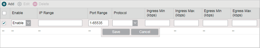
2)Click Add and specify the following parameters.
Figure 8-2 Creating Bandwidth Control Entries
|
Enable |
Enable or disable the desired entry. |
|
IP Range |
Enter the IP Range of the target hosts which need to be controlled of bandwidth, for example 192.168.0.12-192.168.0.25. |
|
Port Range |
Enter the Port Range through which the target hosts visit external server, for example 1-63258. |
|
Protocol |
Choose one of the protocols used for this application: TCP, UDP, or TCP/UDP. |
|
Ingress Min (kbps) |
Specify the minimum ingress bandwidth for the desired entry. |
|
Ingress Max (kbps) |
Specify the maximum ingress bandwidth for the desired entry. |
|
Egress Min (kbps) |
Specify the minimum egress bandwidth for the desired entry. |
|
Egress Max (kbps) |
Specify the maximum egress bandwidth for the desired entry. |
3)Click Save and click Apply, then click Save.
We can effectively prevent ARP attack and IP embezzlement by enabling the IP&MAC binding. Within the local network, the device transmits IP packets to the certain target identified by the MAC address. Therefore, the IP and MAC address should be one-to-one correspondence and their corresponding relations are maintained by the ARP table. ARP attack can use forged information to renewal the ARP table, and destroy the corresponding relations between IP and MAC addresses, which would prevent the communication between the device and the corresponding host. When the IP&MAC Binding function is enabled, the IP and MAC relations in the ARP table won’t be expired and renewed automatically, which effectively prevents the ARP attack.
Some functions such as access control and bandwidth control, are based on the IP addresses to identify the access clients. The network administrator can allocate every client a static IP, according to which he makes the access and bandwidth rules to control the clients’ online behavior and the bandwidth they’ve used. Some illegal users may change the IP address in order to get higher internet access. Enabling IP & MAC binding function can effectively prevent the IP embezzlement.
|
|
Note: After IP & MAC binding function is enabled, the IP bound to the MAC cannot be used by other MACs. However this MAC can use other IPs within the same segment, which are not bounded by other MACs, to access the network. |
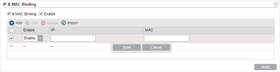
1)Go to the Network page. In the IP & MAC Binding section, click Add and specify the IP address and MAC address.
Click Import to quick import the entries in ARP table to IP & MAC Binding table. The imported entries are disabled by default. You can select the desired entries and click Edit to enable it.
Figure 9-1 Configuring IP & MAC Binding
|
IP |
Enter the IP address that you want to bind with the MAC address. |
|
MAC |
Enter the MAC address that you want to bind with the IP address. |
2)Enable the desired entry and click Save. Click Apply, then click Save.