Configuring the EAPs Globally via Omada Controller
CHAPTERS
5. MAC Filter
6. Scheduler
7. QoS
8. System
|
|
This guide applies to: Omada Controller 2.6.0 |

This guide introduces the global configurations applied to all the managed EAPs via Omada Controller. To configure a specific EAP, please refer to Configuring the EAPs Separately via Omada Controller.
In global configurations, you can configure the following items:
Wireless Network
Access Control
Portal Authentication
Free Authentication Policy
MAC Filter
Scheduler
QoS
System
In addition to the wireless network you created in Quick Start, you can add more wireless networks and configure the advanced wireless parameters to improve the network quality.
1.1Add Wireless Networks
To add wireless networks, follow the steps below.
1)Go to Wireless Settings > Basic Wireless Setting.
Figure 1-1 Wireless Setting
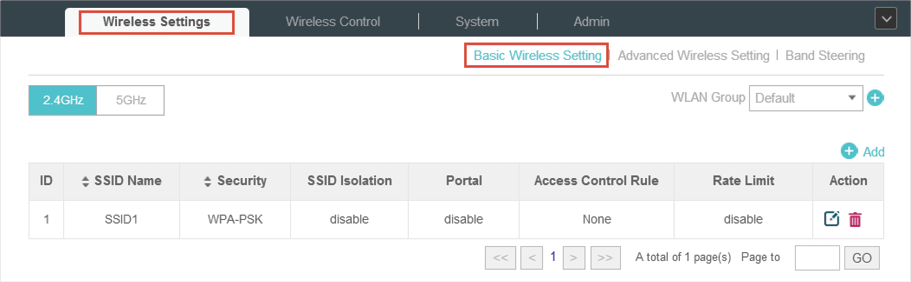
2)Select a band frequency  and click
 at the right of
  to add a WLAN group. Different WLAN groups can be applied to different EAPs. If you have no need to group your wireless networks, you can use the default WLAN group and skip this step.
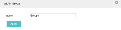
3)Specify a name for the group and click Apply.
Figure 1-2 WLAN Group
4)Select the brand frequency and WLAN group .
5)Click  to add an SSID to the specific WLAN group.
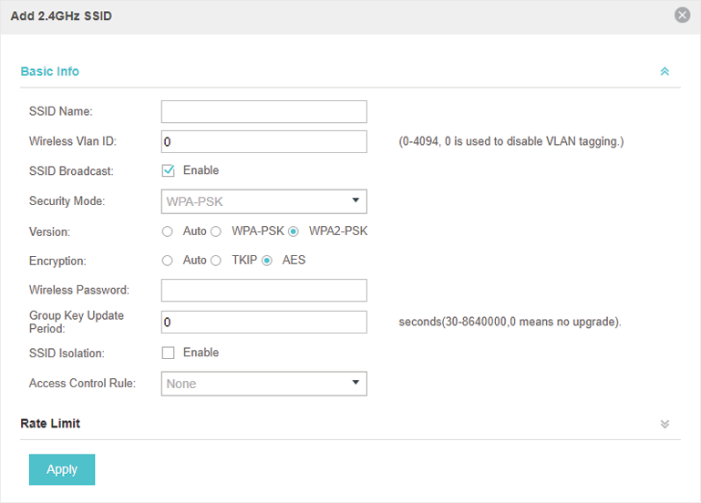
6)Configure the parameters in the following window.
Figure 1-3 Adding a 2.4GHz SSID
|
SSID Name |
Enter an SSID name contains up to 32 characters. |
|
Wireless Vlan ID |
Set a VLAN ID for the wireless network. Wireless networks with the same VLAN ID are grouped to a VLAN. The value ranges from 0 to 4094. 0 means VLAN function is disabled. |
|
SSID Broadcast |
With the option enabled, EAPs will broadcast the SSID to the nearby hosts, so that those hosts can find the wireless network identified by this SSID. If this option is disabled, users must enter the SSID manually to connect to the EAP. Enabled by default. |
|
Security Mode |
Select the security mode of the wireless network. None: The hosts can access the wireless network without authentication. WEP/WPA-Enterprise/WPA-PSK: The hosts need to get authenticated before accessing the wireless network. For the network security, you are suggested to encrypt your wireless network. Settings vary in different security modes and the details are in the following introduction. |
|
Portal |
With the option enabled, the configurations in Portal Authentication will be applied. Portal provides authentication service for the clients who just need temporary access to the wireless network, such as the customers in shopping mall and restaurant. Disabled by default. |
|
SSID Isolation |
With the option enabled, the devices connected in the same SSID of the same AP cannot communicate with each other. Disabled by default. |
|
Access Control |
Select an Access Control rule for this SSID. For more information, refer to Access Control. |
Following is the detailed introduction of WEP, WPA-Enterprise and WPA-PSK.
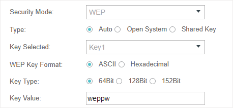
WEP is based on the IEEE 802.11 standard and less safe than WPA-Enterprise and WPA-PSK.
WEP is not supported in 802.11n mode or 802.11ac mode. If WEP is applied in 802.11n, 802.11 ac or 802.11n/ac mixed mode, the clients may not be able to access the wireless network. If WEP is applied in 11b/g/n mode (2.4GHz) or 11a/n (5GHz), the EAP device may work at a low transmission rate.
Figure 1-4 The Page of Setting WEP
|
Type |
Select the authentication type for WEP. Auto: The Omada Controller can select Open System or Shared Key automatically based on the wireless station's capability and request. Open System: Clients can pass the authentication and associate with the wireless network without password. However, correct password is necessary for data transmission. Shared Key: Clients have to input password to pass the authentication, otherwise it cannot associate with the wireless network or transmit data. |
|
Key Selected |
Select one key to specify. You can configure four keys at most. |
|
WEP Key Format |
Select ASCII or Hexadecima as the WEP key format. ASCII: ASCII format stands for any combination of keyboard characters of the specified length. Hexadecimal: Hexadecimal format stands for any combination of hexadecimal digits (0-9, a-f, A-F) with the specified length. |
|
Key Type |
Select the WEP key length for encryption. 64Bit: Enter 10 hexadecimal digits or 5 ASCII characters. 128Bit: Enter 26 hexadecimal digits or 13 ASCII characters. 152Bit: Enter 32 hexadecimal digits or 16 ASCII characters. |
|
Key Value |
Enter the WEP keys. The length and valid characters are affected by key type. |
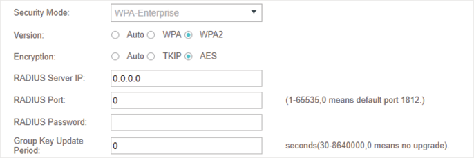
The WPA-Enterprise mode requires a RADIUS server to authenticate clients. Since the WPA-Enterprise can generate different passwords for different clients, it is much safer than WPA-PSK. However, it costs much more to maintain and is usually used by enterprise.
Figure 1-5 The Page of Setting WPA-Enterprise
|
Version |
Select the version of WPA-Enterprise. Auto: The EAP will automatically choose the version used by each client device. WPA/WPA2: Two versions of Wi-Fi Protected Access. |
|
Encryption |
Select the Encryption type. Auto: The default setting is Auto and the EAP will select TKIP or AES automatically based on the client device's request. TKIP: Temporal Key Integrity Protocol. TKIP is not supported in 802.11n mode, 802.11ac mode or 802.11n/ac mixed mode. If TKIP is applied in 802.11n, 802.11 ac or 802.11n/ac mixed mode, the clients may not be able to access the wireless network of the EAP. If TKIP is applied in 11b/g/n mode (2.4GHz) or 11a/n mode(5GHz), the device may work at a low transmission rate. AES: Advanced Encryption Standard. We recommend you select AES as the encryption type because it is more secure than TKIP. |
|
RADIUS Server IP |
Enter the IP address of the RADIUS Server. |
|
RADIUS Port |
Enter the port number of the RADIUS Server. |
|
RADIUS Password |
Enter the shared secret key of the RADIUS server. |
|
Group Key Update Period |
Specify a group key update period, which instructs the EAP how often it should change the encryption keys. The value can be either 0 or 30~8640000 seconds. 0 means no change of the encryption key anytime. |
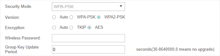
Based on a pre-shared key, WPA-PSK is characterized by high safety and simple settings and is mostly used by common households and small businesses.
Figure 1-6 The Page of Setting WPA-PSK
|
Version |
Select the version of WPA-PSK. Auto: The EAP will automatically choose the version for each client device. WPA-PSK: Pre-shared key of WPA. WAP2-PSK: Pre-shared key of WPA2. |
|
Encryption |
Select the Encryption type. Auto: The default setting is Auto and the EAP will select TKIP or AES automatically based on the client request. TKIP: Temporal Key Integrity Protocol. TKIP is not supported in 802.11n mode, 802.11ac mode or 802.11n/ac mixed mode. If TKIP is applied in 802.11n, 802.11 ac or 802.11n/ac mixed mode, the clients may not be able to access the wireless network of the EAP. If TKIP is applied in 11b/g/n mode (2.4GHz) or 11a/n mode(5GHz), the device may work at a low transmission rate. AES: Advanced Encryption Standard. We recommend you select AES as the encryption type for it is more secure than TKIP. |
|
Wireless Password |
Configure the wireless password with ASCII or Hexadecimal characters. For ASCII, the length should be between 8 and 63 characters with combination of numbers, letters (case-sensitive) and common punctuations. For Hexadecimal, the length should be 64 characters (case-insensitive, 0-9, a-f, A-F). |
|
Group Key Update Period |
Specify a group key update period, which instructs the EAP how often it should change the encryption keys. The value can be either 0 or 30~8640000 seconds. 0 means the encryption keys will not be changed all the time. |
7)Enable Rate Limit for the clients to guarantee the network balance. Enter the value for Download Limit and Upload Limit. 0 means unlimited.
Figure 1-7 Configuring Rate Limit
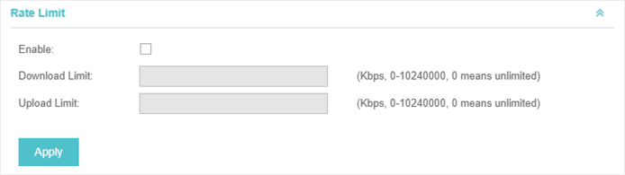
8)Click Apply.
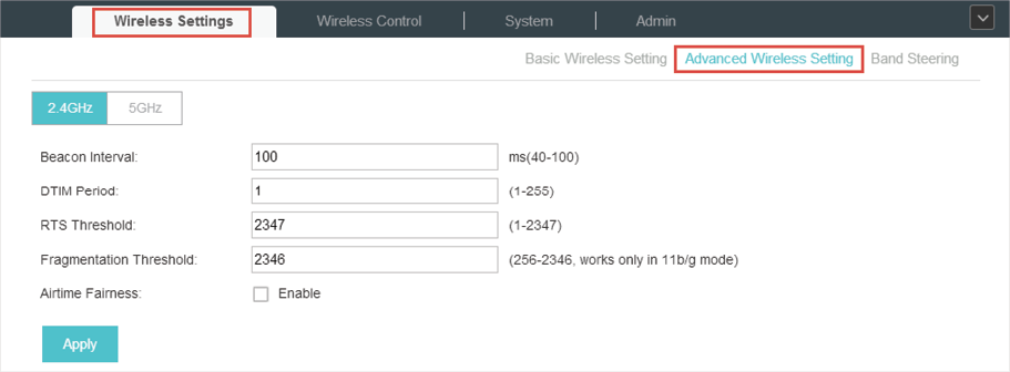
1.2Configure Advanced Wireless Parameters
Proper wireless parameters can improve the network’s stability, reliability and communication efficiency. The advanced wireless parameters consist of Beacon Interval, DTIM Period, RTS Threshold, Fragmentation Threshold and Airtime Fairness.
To configure the advanced wireless parameters, follow the steps below.
1)Go to Wireless Settings > Advanced Wireless Setting.
Figure 1-8 Advanced Wireless Setting
2)Select the band frequency  .
.
3)Configure the following parameters.
|
Beacon Interval |
Beacons are transmitted periodically by the EAP device to announce the presence of a wireless network for the clients. Beacon Interval value determines the time interval of the beacons sent by the device. You can specify a value between 40 and 100ms. The default is 100ms. |
|
DTIM Period |
The DTIM (Delivery Traffic Indication Message) is contained in some Beacon frames. It indicates whether the EAP device has buffered data for client devices. The DTIM Period indicates how often the clients served by this EAP device should check for buffered data still on the EAP device awaiting pickup. You can specify the value between 1-255 Beacon Intervals. The default value is 1, indicating clients check for buffered data on the EAP device at every beacon. An excessive DTIM interval may reduce the performance of multicast applications, so we recommend you keep it by default. |
|
RTS Threshold |
RTS (Request to Send) can ensure efficient data transmission. When RTS is activated, the client will send a RTS packet to EAP to inform that it will send data before it send packets. After receiving the RTS packet, the EAP notices other clients in the same wireless network to delay their transmitting of data and informs the requesting client to send data, thus avoiding the conflict of packet. If the size of packet is larger than the RTS Threshold, the RTS mechanism will be activated. If you specify a low threshold value, RTS packets are sent more frequently and help the network recover from interference or collisions that might occur on a busy network. However, it also consumes more bandwidth and reduces the throughput of the packet. We recommend you keep it by default. The recommended and default value is 2347. |
|
Fragmentation Threshold |
The fragmentation function can limit the size of packets transmitted over the network. If a packet exceeds the Fragmentation Threshold, the fragmentation function is activated and the packet will be fragmented into several packets. Fragmentation helps improve network performance if properly configured. However, too low fragmentation threshold may result in poor wireless performance caused by the extra work of dividing up and reassembling of frames and increased message traffic. The recommended and default value is 2346 bytes. |
|
Airtime Fairness |
With this option enabled, each client connecting to the EAP can get the same amount of time to transmit data, avoiding low-data-rate clients to occupy too much network bandwidth and improving the network throughput. We recommend you enable this function under multi-rate wireless networks. |
4)Click Apply.
1.3Configure Band Steering
A client device that is capable of communicating on both the 2.4GHz and 5GHz frequency bands will typically connect to the 2.4 GHz band. However, if too many client devices are connected to an EAP on the 2.4 GHz band, the efficiency of communication will be diminished. Band Steering can steer clients capable of communication on both bands to the 5GHz frequency band which supports higher transmission rates and more client devices, and thus to greatly improve the network quality.
To configure Band Steering, follow the steps below.
1)Go to Wireless Settings > Band Steering.
Figure 1-9 Configuring Band Steering
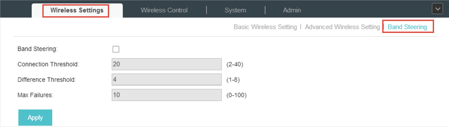
2)Check the box to enable the Band Steering function.
3)Configure the following parameters to balance the clients on both frequency bands:
|
Connection Threshold/Difference Threshold |
When the number of clients on the 5GHz band reaches the value of Connection Threshold and the difference value between the number of clients on the 2.4GHz band and the 5GHz band reaches the value of Difference Threshold, EAPs will refuse the requests of communication on the 5GHz band from other clients and no longer steer other clients to the 5GHz band. The value of Connection Threshold is from 2 to 40, and the default is 20. The value of Difference Threshold is from 1 to 8, and the default is 4. |
|
Max Failures |
If a client repeatedly attempts to associate with the EAP on the 5GHz band and the number of rejections reaches the value of Max Failures, the EAP will accept the request. The value is from 0 to 100, and the default is 10. |
4)Click Apply.
Access Control is used to block or allow the clients to access specific subnets. To configure Access Control rules, follow the steps below.
1)Go to Wireless Control > Access Control.
Figure 2-1 Configuring Access Control
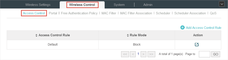
2)Click to add a new Access Control rule.
Figure 2-2 Adding Access Control Rules
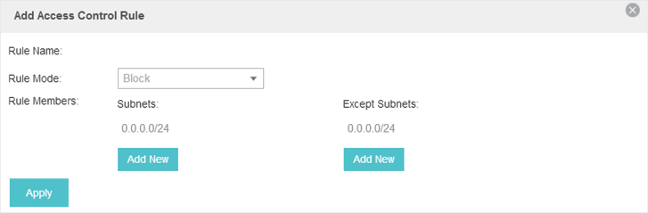
3)Configure the following parameters.
|
Rule Name |
Specify a name for this rule. |
|
Rule Mode |
Select the mode for this rule. Block: Select this mode to block clients to access the specific subnets. Allow: Select this mode to allow clients to access the specific subnets. |
|
Rule Memebers |
Specify the member subnets for this rule. Subnets: Enter the subnet that will follow the rule mode in the format X.X.X.X/X and click Except Subnets: Enter the excepted subnet in the format X.X.X.X/X and click |


4)Click Apply.
5)Go to Wireless Settings > Basic Wireless Setting and enable Access Control function of a selected SSID.
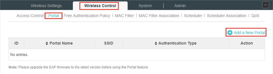
Portal authentication enhances the network security by providing authentication service to the clients that just need temporary access to the wireless network. Such clients have to log into a web page to establish verification, after which they will access the network as guests. What’s more, you can customize the authentication login page and specify a URL which the newly authenticated clients will be redirected to.
To configure Portal Authentication, go to Wireless Control > Portal and click  .
.
Figure 3-1 Portal
Then the following window will pop up:
Figure 3-2 Adding a New Portal
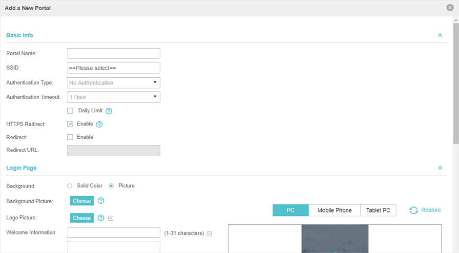
These authentication methods are available: No Authentication, Simple Password, Local User, Voucher, SMS, Facebook, External RADIUS Server and External Portal Server. The following sections introduce how to configure each Portal authentication.
3.1No Authentication
With No Authentication configured, clients can access the network without any authentication.
Follow the steps below to configure No Authentication:
1)Go to Wireless Settings > Basic Wireless Settings and create an SSID for the Portal.
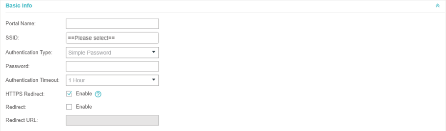
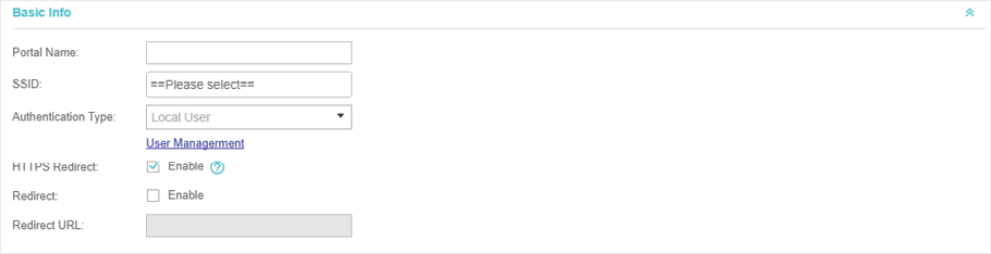
2)Go back to the Portal configuration page. In the Basic Info section, complete the basic settings for the portal authentication.
Figure 3-3 Basic Info
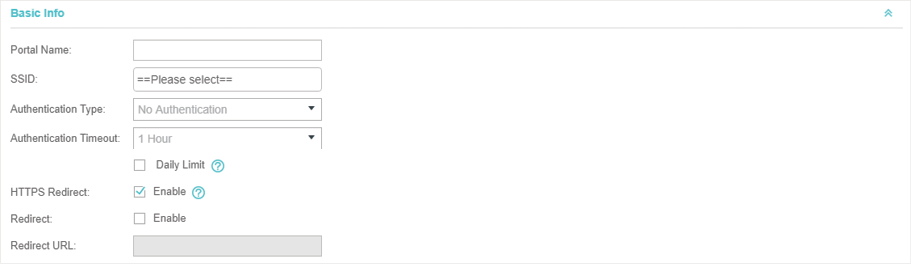
Configure the following parameters:
|
Portal Name |
Specify a name for the Portal. |
|
SSID |
Select an SSID for the Portal. |
|
Authentication Type |
Select No Authentication. |
|
Authentication Timeout |
With Daily Limit disabled, the client's authentication will expire after the time period you set and the client needs to log in on the web authentication page again to access the network. Options include 1 Hour, 8 Hours, 24 Hours, 7 Days and Custom. Custom allows you to define the time in days, hours and minutes. The default value is one hour. With Daily Limit enabled, the client’s authentication will expire after the time period you set and the client cannot log in again in the same day. Options include 30 Minutes, 1 Hour, 2 Hours, 4 Hours and 8 Hours, Custom. Custom allows you to define the time in hours and minutes. The default value is 30 minutes. |
|
Daily Limit |
With Daily Limit enabled, after authentication times out, the user cannot get authenticated again in the same day. |
|
HTTPS Redirect |
With this function enabled, the unauthorized clients will be redirected to the Portal page when they are trying to browse HTTPS websites. With this function disabled, the unauthorized clients cannot browse HTTPS websites or be redirected to the Portal page. |
|
Redirect |
If you enable this function, the portal will redirect the newly authenticated clients to the configured URL. |
|
Redirect URL |
If the Redirect function above is enabled, enter the URL that a newly authenticated client will be redirected to. |
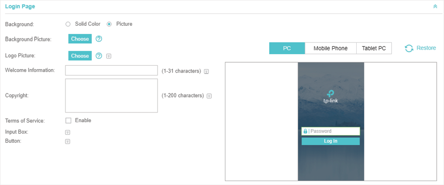
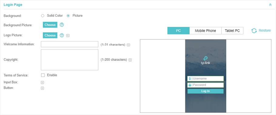
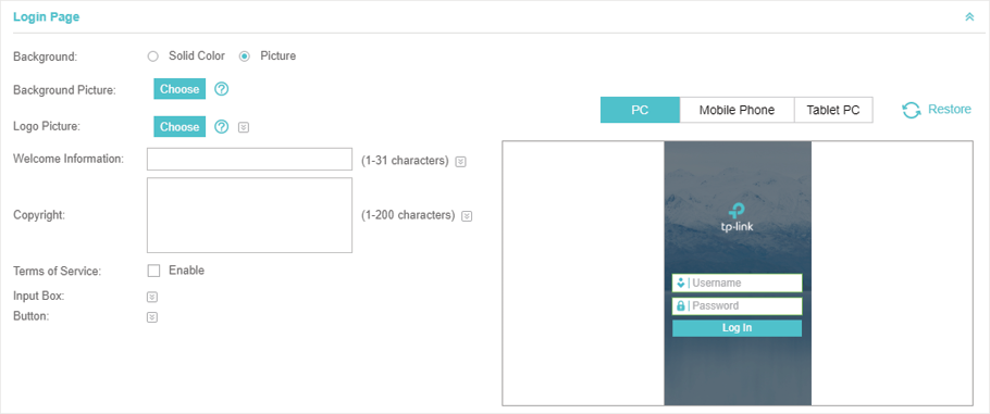
3)In the Login Page section, configure the login page for the Portal.
Figure 3-4 Configuring the Login Page
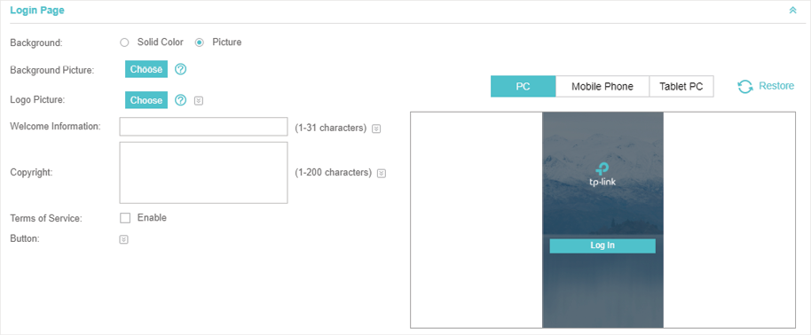
Configure the following parameters:
|
Background |
Select the background type. Two types are supported: Solid Color and Picture. |
|
Background Color |
If Solid Color is selected, configure your desired background color through the color picker or by entering the RGB value manually. |
|
Background Picture |
If Picture is selected, click the Choose button and select a picture from your PC. Drag and scale the clipping region to edit the picture and click Confirm. |
|
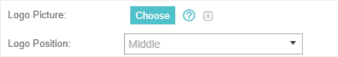
Logo Picture |
Click the Choose button and select a picture from your PC. Drag and scale the clipping region to edit the picture and click Confirm. In addtion, you can click
|
|
Welcome Information |
Specify the welcome information. In addtion, you can click
|
|
Copyright |
Specify the copyright information. In addtion, you can click
|
|
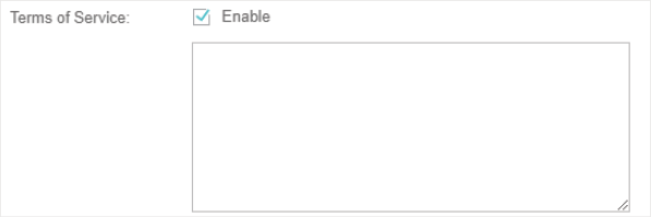
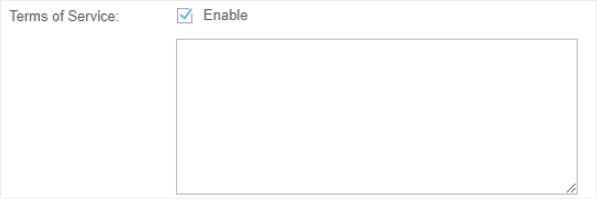
Terms of Service |
Enable or disable Terms of Service. With this option enabled, specify the terms of service in the following box.
|
|
Button |
Click Button Position: Set the position of the login button. The options include Middle, Upper and Lower. Button Color: Select your desired login button color through the color picker or by entering the RGB value manually. Button Text Color: Select your desired text color for the button through the color picker or by entering the RGB value manually.
|
 and configure the logo position. The options include
 and select your desired text color for the welcome information through the color picker or by entering the RGB value manually.
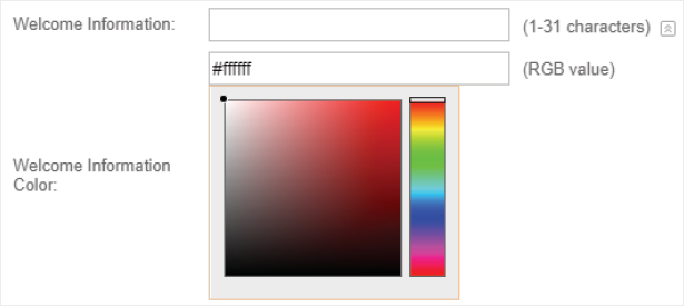
 and select your desired text color for Copyright information through the color picker or by entering the RGB value manually.
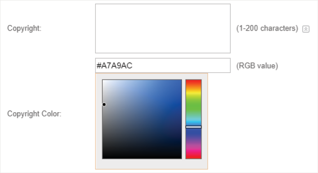
 and configure the button.
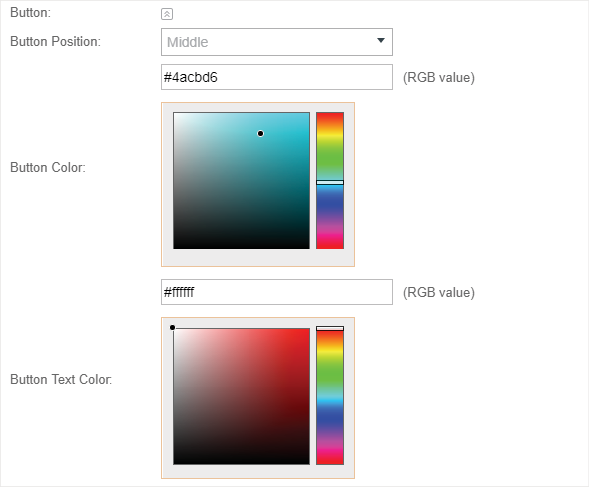
4)In the Advertisement section, select whether display advertisement pictures for users and configure the related parameters.
Figure 3-5 Configuring the Advertisement

Configure the following parameters:
|
Advertisement |
Specify whether to enable the Advertisement feature. With this feature enabled, you can add advertisement pictures on the authentication page. These advertisement pictures will be displayed before the login page appears. You can also allow users to skip the advertisement by enabling Allow to Skip Advertisement. |
|
Picture Resource |
Upload advertisement pictures. When several pictures are added, they will be played in a loop. |
|
Advertisement Duration Time |
Specify how long the advertisement will be displayed for. For this duration, the pictures will be played in a loop. If the duration time is not enough for all the pictures, the rest will not be displayed. |
|
Picture Careusel Interval |
Specify the picture carousel interval. For example, if this value is set as 5 seconds, the first picture will be displayed for 5 seconds, followed by the second picture for 5 seconds, and so on. |
|
Allow Users To Skip Advertisement |
Specify whether to enable this feature. With this feature enabled, the user can click the Skip button to skip the advertisement. |
5)Click Apply.
3.2Simple Password
With this Simple Password configured, clients are required to enter the correct password to pass the authentication.
Follow the steps below to configure No Simple Password Portal:
1)Go to Wireless Settings > Basic Wireless Settings and create an SSID for the Portal.
2)Go back to the Portal configuration page. In the Basic Info section, complete the basic settings for the portal authentication.
Figure 3-6 Basic Info
Configure the following parameters:
|
Portal Name |
Specify a name for the Portal. |
|
SSID |
Select an SSID for the Portal. |
|
Authentication Type |
Select Simple Password. |
|
Password |
Set the password for authentication. |
|
Authentication Timeout |
The client's authentication will expire after the time period you set and the client needs to log in the web authentication page again to access the network. Options include 1 Hour, 8 Hours, 24 Hours, 7 Days and Custom. Custom allows you to define the time in days, hours and minutes. The default value is one hour. |
|
HTTPS Redirect |
With this function enabled, the unauthorized clients will be redirected to the Portal page when they are trying to browse HTTPS websites. With this function disabled, the unauthorized clients cannot browse HTTPS websites or be redirected to the Portal page. |
|
Redirect |
If you enable this function, the portal will redirect the newly authenticated clients to the configured URL. |
|
Redirect URL |
If the Redirect function above is enabled, enter the URL that a newly authenticated client will be redirected to. |
3)In the Login Page section, configure the login page for the Portal.
Figure 3-7 Configuring the Login Page
Configure the following parameters:
|
Background |
Select the background type. Two types are supported: Solid Color and Picture. |
|
Background Color |
If Solid Color is selected, configure your desired background color through the color picker or by entering the RGB value manually. |
|
Background Picture |
If Picture is selected, click the Choose button and select a picture from your PC. Drag and scale the clipping region to edit the picture and click Confirm. |
|
Logo Picture |
Click the Choose button and select a picture from your PC. Drag and scale the clipping region to edit the picture and click Confirm. In addtion, you can click
|
|
Welcome Information |
Specify the welcome information. In addtion, you can click
|
|
Copyright |
Specify the copyright information. In addtion, you can click
|
|
Terms of Service |
Enable or disable Terms of Service. With this option enabled, specify the terms of service in the following box.
|
|
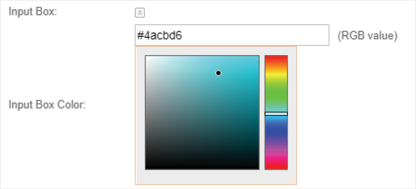
Input Box |
Click Select your desired color for the input box through the color picker or by entering the RGB value manually.
|
|
Button |
Click Button Position: Set the position of the login button. The options include Middle, Upper and Lower. Button Color: Select your desired login button color through the color picker or by entering the RGB value manually. Button Text Color: Select your desired text color for the button through the color picker or by entering the RGB value manually.
|
 and configure the logo position. The options include
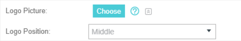

 and select your desired text color for Copyright information through the color picker or by entering the RGB value manually.

 and configure the input box.
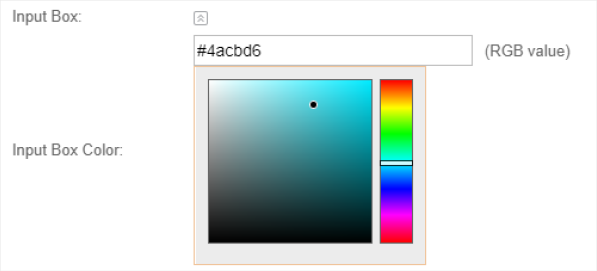
4)In the Advertisement section, select whether display advertisement pictures for users and configure the related parameters.
Figure 3-8 Configuring the Advertisement
Configure the following parameters:
|
Advertisement |
Specify whether to enable the Advertisement feature. With this feature enabled, you can add advertisement pictures on the authentication page. These advertisement pictures will be displayed before the login page appears. You can also allow users to skip the advertisement by enabling Allow to Skip Advertisement. |
|
Picture Resource |
Upload advertisement pictures. When several pictures are added, they will be played in a loop. |
|
Advertisement Duration Time |
Specify how long the advertisement will be displayed for. For this duration, the pictures will be played in a loop. If the duration time is not enough for all the pictures, the rest will not be displayed. |
|
Picture Careusel Interval |
Specify the picture carousel interval. For example, if this value is set as 5 seconds, the first picture will be displayed for 5 seconds, followed by the second picture for 5 seconds, and so on. |
|
Allow Users To Skip Advertisement |
Specify whether to enable this feature. With this feature enabled, the user can click the Skip button to skip the advertisement. |
5)Click Apply.
3.3Local User
With this Local User configured, clients are required to enter the correct username and password of the login account to pass the authentication. You can create multiple accounts and assign different accounts for different users.
Configure Local User Portal
Follow the steps below to configure Local User Portal:
1)Go to Wireless Settings > Basic Wireless Settings and create an SSID for the Portal.
2)Go back to the Portal configuration page. In the Basic Info section, complete the basic settings for the portal authentication.
Figure 3-9 Basic Info
Configure the following parameters:
|
Portal Name |
Specify a name for the Portal. |
|
SSID |
Select an SSID for the Portal. |
|
Authentication Type |
Select Local User. |
|
User Management |
You can click this button to configure user accounts for authentication later. Please refer to Create Local User Accounts. |
|
HTTPS Redirect |
With this function enabled, the unauthorized clients will be redirected to the Portal page when they are trying to browse HTTPS websites. With this function disabled, the unauthorized clients cannot browse HTTPS websites or be redirected to the Portal page. |
|
Redirect |
If you enable this function, the portal will redirect the newly authenticated clients to the configured URL. |
|
Redirect URL |
If the Redirect function above is enabled, enter the URL that a newly authenticated client will be redirected to. |
3)In the Login Page section, configure the login page for the Portal.
Figure 3-10 Configuring the Login Page
Configure the following parameters:
|
Background |
Select the background type. Two types are supported: Solid Color and Picture. |
|
Background Color |
If Solid Color is selected, configure your desired background color through the color picker or by entering the RGB value manually. |
|
Background Picture |
If Picture is selected, click the Choose button and select a picture from your PC. Drag and scale the clipping region to edit the picture and click Confirm. |
|
Logo Picture |
Click the Choose button and select a picture from your PC. Drag and scale the clipping region to edit the picture and click Confirm. In addtion, you can click
|
|
Welcome Information |
Specify the welcome information. In addtion, you can click
|
|
Copyright |
Specify the copyright information. In addtion, you can click
|
|
Terms of Service |
Enable or disable Terms of Service. With this option enabled, specify the terms of service in the following box.
|
|
Input Box |
Click Select your desired color for the input box through the color picker or by entering the RGB value manually.
|
|
Button |
Click Button Position: Set the position of the login button. The options include Middle, Upper and Lower. Button Color: Select your desired login button color through the color picker or by entering the RGB value manually. Button Text Color: Select your desired text color for the button through the color picker or by entering the RGB value manually.
|
 and select your desired text color for the welcome information through the color picker or by entering the RGB value manually.
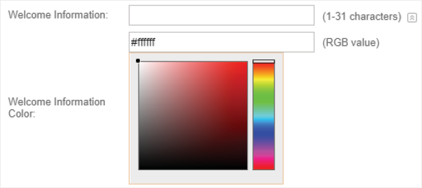

4)In the Advertisement section, select whether display advertisement pictures for users and configure the related parameters.
Figure 3-11 Configuring the Advertisement
Configure the following parameters:
|
Advertisement |
Specify whether to enable the Advertisement feature. With this feature enabled, you can add advertisement pictures on the authentication page. These advertisement pictures will be displayed before the login page appears. You can also allow users to skip the advertisement by enabling Allow to Skip Advertisement. |
|
Picture Resource |
Upload advertisement pictures. When several pictures are added, they will be played in a loop. |
|
Advertisement Duration Time |
Specify how long the advertisement will be displayed for. For this duration, the pictures will be played in a loop. If the duration time is not enough for all the pictures, the rest will not be displayed. |
|
Picture Careusel Interval |
Specify the picture carousel interval. For example, if this value is set as 5 seconds, the first picture will be displayed for 5 seconds, followed by the second picture for 5 seconds, and so on. |
|
Allow Users To Skip Advertisement |
Specify whether to enable this feature. With this feature enabled, the user can click the Skip button to skip the advertisement. |
5)Click Apply.
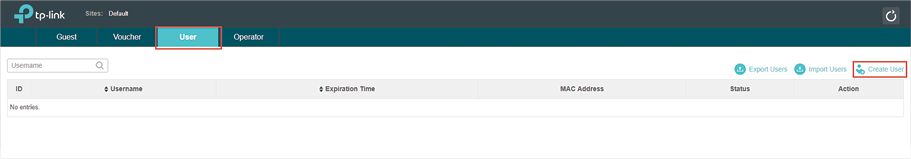
Follow the steps below to create the user accounts for authentication:
1)In the Basic Info section on the portal configuration page, click User Management. The management page will appear. Go to the User page and click  .
.
Figure 3-12 Creating Local User Accounts
2)The following window will pop up. Configure the required parameters and click Apply.
Figure 3-13 Creating a New User
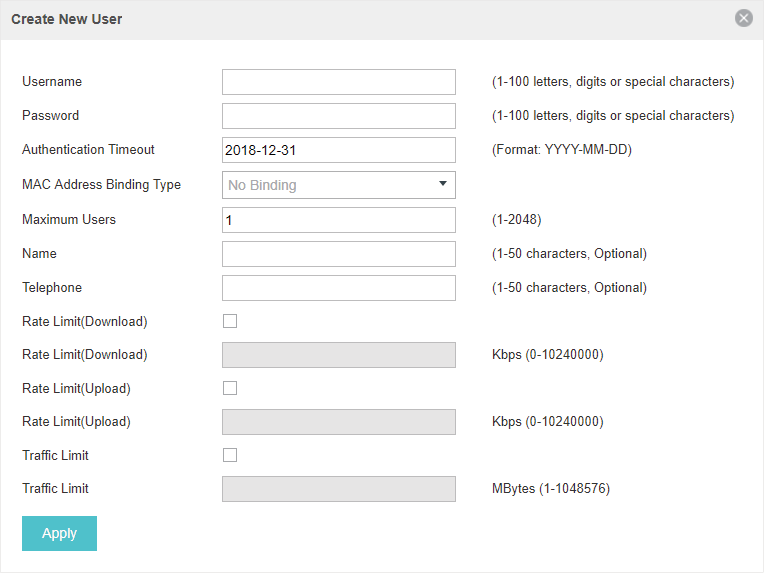
Configure the following parameters:
|
Username |
Specify the username. The username should not be the same as any existing one. |
|
Password |
Specify the password. Users will be required to enter the username and password when they attempt to access the network. |
|
Authentication Timeout |
Specify the authentication timeout for formal users. After timeout, the users need to log in at the web authentication page again to access the network. |
|
MAC Address Binding Type |
There are three types of MAC binding: No Binding, Static Binding and Dynamic Binding. Static Binding: Specify a MAC address for this user account. Then only the user with the this MAC address can use the username and password to pass the authentication. Dynamic Binding: The MAC address of the first user that passes the authentication will be bound. Then only this user can use the username and password to pass the authentication. |
|
Maximum Users |
Specify the maximum number of users able to use this account to pass the authencitation. |
|
Name |
Specify a name for identification. |
|
Telephone |
Specify a telephone number for identification. |
|
Rate Limit (Download) |
Select whether to enable download rate limit. With this option enabled, you can specify the limit of download rate. |
|
Rate Limit (Upload) |
Select whether to enable upload rate limit. With this option enabled, you can specify the limit of upload rate. |
|
Traffic Limit |
Select whether to enable traffic limit. With this option enabled, you can specify the total traffic limit for the user. Once the limit is reached, the user can no longer use this account to access the network. |
3)In the same way, you can add more user accounts. The created user accounts will be displayed in the list. Users can use the username and password of the account to pass the portal authentication.
By default, the account Status is  , which means that the user account is enabled and valid. You can also click this button to disable the user account. The icon will be changed to
  , which means that the user account is disabled.
Figure 3-14 The User Page
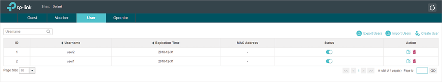
Additionally, you can click  to backup all the user account information into a CSV file or XLS file and save the file to your PC. If needed, you can click
  and select the file to import the account information to the list.
|
|
Note: Using Excel to open the CSV file may cause some numerical format changes, and the number may be displayed incorrectly. If you use Excel to edit the CSV file, please set the cell format as text. |

Manage the Guests
On the Guest page, you can view the information of clients that have passed the portal authentication and manage the clients.
Figure 3-15 The Guest Page
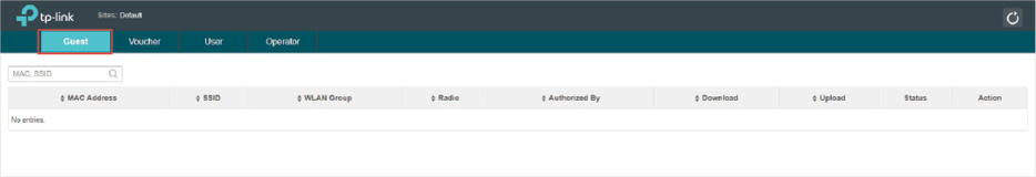
You can select an icon to execute the corresponding operation:
|
|
Disconnect client. |
|
|
Extend the effective time. |


Create Operator Accounts
Operator account can be used to remotely manage the Local User Portal and Voucher Portal. Other users can visit the URL https://Omada Controller Host’s IP Address:8043/hotspot (For example: https://192.168.0.64:8043/hotspot) and use the Operator account to enter the portal management page.
|
|
Note: The users who enter the portal management page by Operator account can only create local user accounts and vouchers and manage the clients. |
Follow the steps below to create Operator account.
1)Go to the Operator page.
Figure 3-16 The Operator Page
2)Click  and the following window will pop up.
Figure 3-17 Creating a New Operator Account
3)Specify the Name, Password and Notes of the Operator account.
4)Choose Site Privileges (more than one options can be chosen) for the Operator account.
5)Click Apply to create an Operator account. Then other users can use this account to enter the hotspot management page.
3.4Voucher
With Voucher configured, you can distribute the vouchers automatically generated by the Omada Controller to the clients. Clients can use the vouchers to access the network.
Configure Voucher Portal
Follow the steps below to configure Voucher Portal:
1)Go to Wireless Settings > Basic Wireless Settings and create an SSID for the Portal.
2)Go back to the Portal configuration page. In the Basic Info section, complete the basic settings for the portal authentication.
Figure 3-18 Basic Info
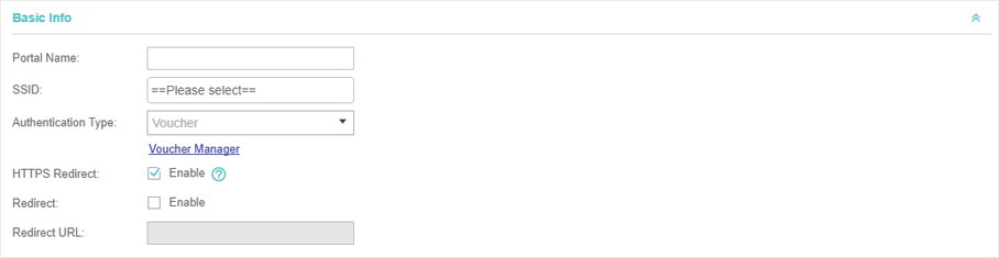
Configure the following parameters:
|
Portal Name |
Specify a name for the Portal. |
|
SSID |
Select an SSID for the Portal. |
|
Authentication Type |
Select Voucher. |
|
User Management |
You can click this button to configure vouchers for authentication later. Please refer to Create Vouchers. |
|
HTTPS Redirect |
With this function enabled, the unauthorized clients will be redirected to the Portal page when they are trying to browse HTTPS websites. With this function disabled, the unauthorized clients cannot browse HTTPS websites or be redirected to the Portal page. |
|
Redirect |
If you enable this function, the portal will redirect the newly authenticated clients to the configured URL. |
|
Redirect URL |
If the Redirect function above is enabled, enter the URL that a newly authenticated client will be redirected to. |
3)In the Login Page section, configure the login page for the Portal.
Figure 3-19 Configuring the Login Page
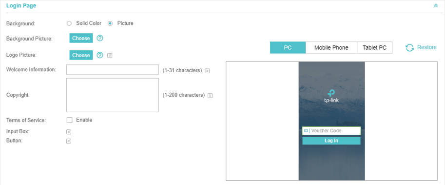
Configure the following parameters:
|
Background |
Select the background type. Two types are supported: Solid Color and Picture. |
|
Background Color |
If Solid Color is selected, configure your desired background color through the color picker or by entering the RGB value manually. |
|
Background Picture |
If Picture is selected, click the Choose button and select a picture from your PC. Drag and scale the clipping region to edit the picture and click Confirm. |
|
Logo Picture |
Click the Choose button and select a picture from your PC. Drag and scale the clipping region to edit the picture and click Confirm. In addtion, you can click
|
|
Welcome Information |
Specify the welcome information. In addtion, you can click
|
|
Copyright |
Specify the copyright information. In addtion, you can click
|
|
Terms of Service |
Enable or disable Terms of Service. With this option enabled, specify the terms of service in the following box.
|
|
Input Box |
Click Select your desired color for the input box through the color picker or by entering the RGB value manually.
|
|
Button |
Click Button Position: Set the position of the login button. The options include Middle, Upper and Lower. Button Color: Select your desired login button color through the color picker or by entering the RGB value manually. Button Text Color: Select your desired text color for the button through the color picker or by entering the RGB value manually.
|


4)In the Advertisement section, select whether display advertisement pictures for users and configure the related parameters.
Figure 3-20 Configuring the Advertisement
Configure the following parameters:
|
Advertisement |
Specify whether to enable the Advertisement feature. With this feature enabled, you can add advertisement pictures on the authentication page. These advertisement pictures will be displayed before the login page appears. You can also allow users to skip the advertisement by enabling Allow to Skip Advertisement. |
|
Picture Resource |
Upload advertisement pictures. When several pictures are added, they will be played in a loop. |
|
Advertisement Duration Time |
Specify how long the advertisement will be displayed for. For this duration, the pictures will be played in a loop. If the duration time is not enough for all the pictures, the rest will not be displayed. |
|
Picture Careusel Interval |
Specify the picture carousel interval. For example, if this value is set as 5 seconds, the first picture will be displayed for 5 seconds, followed by the second picture for 5 seconds, and so on. |
|
Allow Users To Skip Advertisement |
Specify whether to enable this feature. With this feature enabled, the user can click the Skip button to skip the advertisement. |
5)Click Apply.
Follow the steps below to create vouchers for authentication:
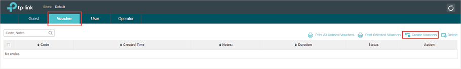
1)In the Basic Info section, click Voucher Manager. The voucher management page will appear. Go to the Voucher page and click  .
.
Figure 3-21 The Voucher Page
2)The following window will pop up. Configure the required parameters and click Apply.
Figure 3-22 Creating Vouchers
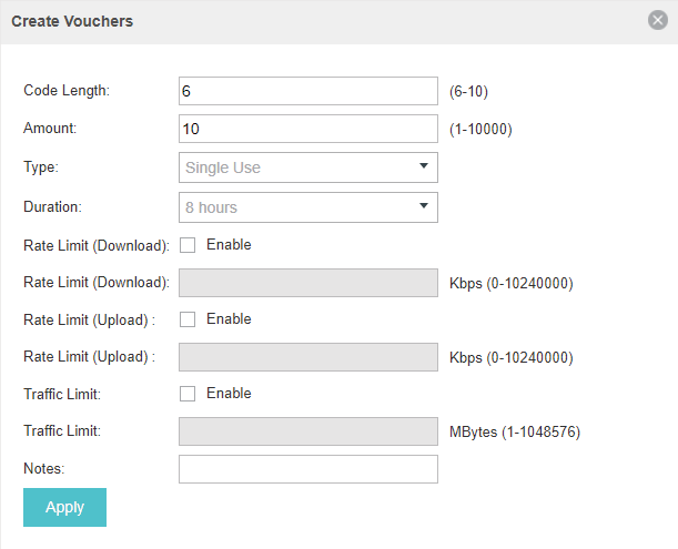
Configure the following parameters:
|
Code Length |
Specify the length of the voucher codes to be created. |
|
Amount |
Enter the voucher amount to be generated. |
|
Type |
Select Single Use or Multi Use. Single Use means one voucher can only be distributed to one client. Multi Use means one voucher can be distributed to several clients, who can use the same voucher to access the network at the same time. If you select Multi Use, enter the value of Max Users. When the number of clients who are connected to the network with the same voucher reaches the value, no more clients can use this voucher to access the network. |
|
Duration |
Select the period of validity of the Voucher. The options include 8 hours, 2 days and User-defined. The period of valid of the voucher is reckoned from the time when it is used for the first time. |
|
Rate Limit (Download) |
Select whether to enable download rate limit. With this option enabled, you can specify the limit of download rate. |
|
Rate Limit (Upload) |
Select whether to enable upload rate limit. With this option enabled, you can specify the limit of upload rate. |
|
Traffic Limit |
Specify the total traffic limit for one voucher. Once the limit is reached, the client can no longer access the network using the voucher. |
|
Notes |
Enter a description for the Voucher (optional). |
3)The Vouchers will be generated and displayed on the page.
Figure 3-23 The Voucher Page
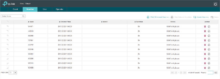
4)Click  to print a single voucher; click
  to print your selected vouchers; click
  to print all unused vouchers.
Figure 3-24 The Vouchers
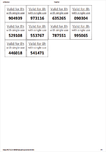
5)Distribute the vouchers to clients, and then they can use the codes to pass authentication.
6)When the vouchers are invalid, you can click to delete the Voucher or click
  to delete the selected vouchers.
Manage the Guests
On the Guest page, you can view the information of clients that have passed the portal authentication and manage the clients.
Figure 3-25 The Guest Page
You can select an icon to execute the corresponding operation:
|
|
Restrict the client to access the network. |
|
|
Extend the effective time. |
Create Operator Accounts
Operator account can be used to remotely manage the Local User Portal and Voucher Portal. Other users can visit the URL https://Omada Controller Host’s IP Address:8043/hotspot (For example: https://192.168.0.64:8043/hotspot) and use the Operator account to enter the portal management page.
|
|
Note: The users who enter the portal management page by Operator account can only create local user accounts and vouchers and manage the clients. |
Follow the steps below to create Operator account.
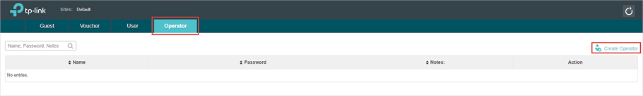
1)Go to the Operator page.
Figure 3-26 The Operator Page
2)Click  and the following window will pop up.
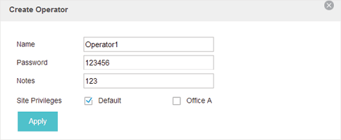
Figure 3-27 Creating a New Operator
3)Specify the Name, Password and Notes of the Operator account.
4)Choose Site Privileges (more than one options can be chosen) for the Operator account.
5)Click Apply to create an Operator account. Then other users can use this account to enter the hotspot administrative system.
3.5SMS
With SMS portal configured, client can get verification codes using their mobile phones and enter the received codes to pass the authentication.
Follow the steps below to configure SMS Portal:
1)Go to www.twilio.com/try-twilio and get a Twilio account. Buy the Twilio service for SMS. Then get the account information, including ACCOUNT SID, AUTH TOKEN and Phone number.
2)Go to Wireless Settings > Basic Wireless Settings and create an SSID for the Portal.
3)Go back to the Portal configuration page. In the Basic Info section, complete the basic settings for the portal authentication.
Figure 3-28 Basic Info
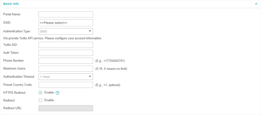
Configure the following parameters:
|
Portal Name |
Specify a name for the Portal. |
|
SSID |
Select an SSID for the Portal. |
|
Authentication Type |
Select SMS. |
|
Twilio SID |
Enter the Account SID for Twilio API Credentials. |
|
Auth Token |
Enter the Authentication Token for Twilio API Credentials. |
|
Phone Number |
Enter the phone number that is used to send verification messages to the clients. |
|
Maximum Users |
A telephone can get several codes via messages one by one, and different clients can use different codes to pass the authentication. However, the number of clients that are allowed to be authenticated using the same telephone at the same time has a upper limit. Specify the upper limit in this field. |
|
Authentication Timeout |
The client's authentication will expire after the time period you set and the client needs to log in the web authentication page again to access the network. Options include 1 Hour, 8 Hours, 24 Hours, 7 Days and Custom. Custom allows you to define the time in days, hours and minutes. The default value is one hour. |
|
Preset Country Code |
Set the default country code that will be filled automatically on the authentication page. |
|
HTTPS Redirect |
With this function enabled, the unauthorized clients will be redirected to the Portal page when they are trying to browse HTTPS websites. With this function disabled, the unauthorized clients cannot browse HTTPS websites or be redirected to the Portal page. |
|
Redirect |
If you enable this function, the portal will redirect the newly authenticated clients to the configured URL. |
|
Redirect URL |
If the Redirect function above is enabled, enter the URL that a newly authenticated client will be redirected to. |
4)In the Login Page section, configure the login page for the Portal.
Figure 3-29 Configuring the Login Page
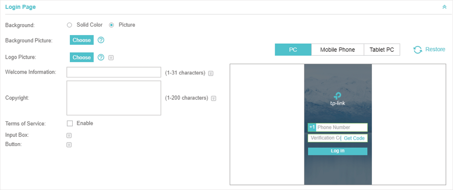
Configure the following parameters:
|
Background |
Select the background type. Two types are supported: Solid Color and Picture. |
|
Background Color |
If Solid Color is selected, configure your desired background color through the color picker or by entering the RGB value manually. |
|
Background Picture |
If Picture is selected, click the Choose button and select a picture from your PC. Drag and scale the clipping region to edit the picture and click Confirm. |
|
Logo Picture |
Click the Choose button and select a picture from your PC. Drag and scale the clipping region to edit the picture and click Confirm. In addtion, you can click
|
|
Welcome Information |
Specify the welcome information. In addtion, you can click
|
|
Copyright |
Specify the copyright information. In addtion, you can click
|
|
Terms of Service |
Enable or disable Terms of Service. With this option enabled, specify the terms of service in the following box.
|
|
Input Box |
Click Select your desired color for the input box through the color picker or by entering the RGB value manually.
|
|
Button |
Click Button Position: Set the position of the login button. The options include Middle, Upper and Lower. Button Color: Select your desired login button color through the color picker or by entering the RGB value manually. Button Text Color: Select your desired text color for the button through the color picker or by entering the RGB value manually.
|
5)In the Advertisement section, select whether display advertisement pictures for users and configure the related parameters.
Figure 3-30 Configuring the Advertisement
Configure the following parameters:
|
Advertisement |
Specify whether to enable the Advertisement feature. With this feature enabled, you can add advertisement pictures on the authentication page. These advertisement pictures will be displayed before the login page appears. You can also allow users to skip the advertisement by enabling Allow to Skip Advertisement. |
|
Picture Resource |
Upload advertisement pictures. When several pictures are added, they will be played in a loop. |
|
Advertisement Duration Time |
Specify how long the advertisement will be displayed for. For this duration, the pictures will be played in a loop. If the duration time is not enough for all the pictures, the rest will not be displayed. |
|
Picture Careusel Interval |
Specify the picture carousel interval. For example, if this value is set as 5 seconds, the first picture will be displayed for 5 seconds, followed by the second picture for 5 seconds, and so on. |
|
Allow Users To Skip Advertisement |
Specify whether to enable this feature. With this feature enabled, the user can click the Skip button to skip the advertisement. |
6)Click Apply.
For more details about how to configure SMS Portal, you can go to https://www.tp-link.com/en/configuration-guides.html and download the configuzration guide for SMS Portal.
3.6Facebook
With Facebook Portal configured, when clients connect to your Wi-Fi, they will be redirected to your Facebook page. To access the internet, clients need to pass the authentication on the page.
|
|
Note: Omada Controller will automatically create Free Authentication Policy entries for the Facebook Portal. You don’t need to create them manually. |
Follow the steps below to configure Facebook Portal:
1)Go to www.facebook.com and get a Facebook account. Create your Facebook page according to your needs.
2)Go to Wireless Settings > Basic Wireless Settings and create an SSID for the Portal.
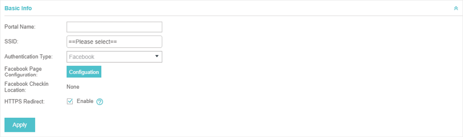
3)Go back to the Portal configuration page. In the Basic Info section, complete the settings for the portal authentication.
Figure 3-31 Basic Info
Configure the following parameters:
|
Portal Name |
Specify a name for the Portal. |
|
SSID |
Select an SSID for the Portal. |
|
Authentication Type |
Select Facebook. |
|
Facebook Page Configuration |
Click this button to specify the Facebook Page. |
|
Facebook Checkin Location |
If the Facebook page is successfully got by the Omada Controller, the name of the Facebook page will be displayed here. |
|
HTTPS Redirect |
With this function enabled, the unauthorized clients will be redirected to the Portal page when they are trying to browse HTTPS websites. With this function disabled, the unauthorized clients cannot browse HTTPS websites or be redirected to the Portal page. |
For more details about how to configure Facebook Portal, you can go to https://www.tp-link.com/en/configuration-guides.html and download the configuration guide for Facebook Portal.
3.7External RADIUS Server
If you have a RADIUS server, you can configure External RADIUS Server Portal. With this type of portal, you can get two types of portal customization: Local Web Portal and External Web Portal. The authentication login page of Local Web Portal is provided by the built-in portal server of the EAP. The External Web Portal is provided by external portal server.
|
|
Note: Omada Controller will automatically create Free Authentication Policy entries for the External RADIUS Portal. |
Follow the steps below to configure External RADIUS Server Portal:
1)Go to Wireless Settings > Basic Wireless Settings and create an SSID for the Portal.
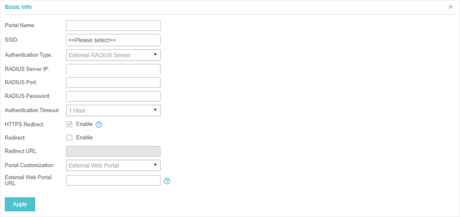
2)Go back to the Portal configuration page. In the Basic Info section, complete the basic settings for the portal authentication.
Figure 3-32 Basic Info
Configure the following parameters:
|
Portal Name |
Specify a name for the Portal. |
|
SSID |
Select an SSID for the Portal. |
|
Authentication Type |
Select Simple Password. |
|
RADIUS Server IP |
Enter the IP address of the RADIUS server. |
|
RADIUS Port |
Enter the port number you have set on the RADIUS server. |
|
RADIUS Password |
Enter the password you have set on the RADIUS Server. |
|
Authentication Timeout |
The client's authentication will expire after the time period you set and the client needs to log in the web authentication page again to access the network. Options include 1 Hour, 8 Hours, 24 Hours, 7 Days, Custom. Custom allows you to define the time in days, hours, and minutes. The default value is one hour. |
|
HTTPS Redirect |
With this function enabled, the unauthorized clients will be redirected to the Portal page when they are trying to browse HTTPS websites. With this function disabled, the unauthorized clients cannot browse HTTPS websites or be redirected to the Portal page. |
|
Redirect |
If you enable this function, the portal will redirect the newly authenticated clients to the configured URL. Disabled by default. |
|
Redirect URL |
If the Redirect function above is enabled, enter the URL that a newly authenticated client will be redirected to. |
|
Portal Customization |
Select Local Web Portal or External Web Portal. Local Web Portal: If this option is selected, refer to step 4 to configure the login page and step 5 to configure the advertisement. External Web Portal: If this option is selected, follow the steps below. 1. Configure the external RADIUS server. 2. Enter the authentication login page's URL provided by the external portal server in the External Web Portal URL field. 3. Put the external web portal server to a whitelist of Free Authentication Policy, otherwise clients cannot access it before authenticated. |
3)Local Web Portal is configured, configure the login page for the Portal in the Login Page section.
Figure 3-33 Configuring the Login Page
Configure the following parameters:
|
Background |
Select the background type. Two types are supported: Solid Color and Picture. |
|
Background Color |
If Solid Color is selected, configure your desired background color through the color picker or by entering the RGB value manually. |
|
Background Picture |
If Picture is selected, click the Choose button and select a picture from your PC. Drag and scale the clipping region to edit the picture and click Confirm. |
|
Logo Picture |
Click the Choose button and select a picture from your PC. Drag and scale the clipping region to edit the picture and click Confirm. In addtion, you can click
|
|
Welcome Information |
Specify the welcome information. In addtion, you can click
|
|
Copyright |
Specify the copyright information. In addtion, you can click
|
|
Terms of Service |
Enable or disable Terms of Service. With this option enabled, specify the terms of service in the following box.
|
|
Input Box |
Click Select your desired color for the input box through the color picker or by entering the RGB value manually.
|
|
Button |
Click Button Position: Set the position of the login button. The options include Middle, Upper and Lower. Button Color: Select your desired login button color through the color picker or by entering the RGB value manually. Button Text Color: Select your desired text color for the button through the color picker or by entering the RGB value manually.
|


4)If Local Web Portal is configured, select whether display advertisement pictures for users and configure the related parameters in the Advertisement section.
Figure 3-34 Configuring the Advertisement
Configure the following parameters:
|
Advertisement |
Specify whether to enable the Advertisement feature. With this feature enabled, you can add advertisement pictures on the authentication page. These advertisement pictures will be displayed before the login page appears. You can also allow users to skip the advertisement by enabling Allow to Skip Advertisement. |
|
Picture Resource |
Upload advertisement pictures. When several pictures are added, they will be played in a loop. |
|
Advertisement Duration Time |
Specify how long the advertisement will be displayed for. For this duration, the pictures will be played in a loop. If the duration time is not enough for all the pictures, the rest will not be displayed. |
|
Picture Careusel Interval |
Specify the picture carousel interval. For example, if this value is set as 5 seconds, the first picture will be displayed for 5 seconds, followed by the second picture for 5 seconds, and so on. |
|
Allow Users To Skip Advertisement |
Specify whether to enable this feature. With this feature enabled, the user can click the Skip button to skip the advertisement. |
5)Click Apply.
3.8External Portal Server
The option of External Portal Server is designed for the developers. They can customized their own authentication type according to the interface provided by Omada Controller, e.g. message authentication and WeChat authentication etc.
1)Go to Wireless Settings > Basic Wireless Settings and create an SSID for the Portal.
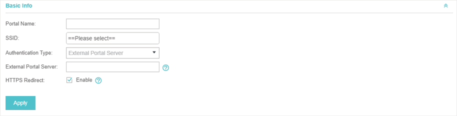
2)Go back to the Portal configuration page. In the Basic Info section, complete the settings for the portal authentication.
Figure 3-35 Basic Info
|
Portal Name |
Specify a name for the Portal. |
|
SSID |
Select an SSID for the Portal. |
|
Authentication Type |
Select External Portal Server. |
|
External Portal Server |
Enter the complete authentication URL that redirect to an external portal server, for example: http://192.168.0.147:8880/portal/index.php or http://192.168.0.147/portal/index.html |
|
HTTPS Redirect |
With this function enabled, the unauthorized clients will be redirected to the Portal page when they are trying to browse HTTPS websites. With this function disabled, the unauthorized clients cannot browse HTTPS websites or be redirected to the Portal page. |
3)Click Apply.
Free Authentication Policy allows some specified clients to access the network resources without authentication. Follow the steps below to add free authentication policy.
1)Go to Wireless Control > Free Authentication Policy.
Figure 4-1 Free Authentication Policy
Fre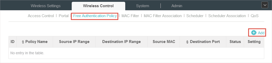
2)Click  and the following window will pop up.
Figure 4-2 Adding a Policy
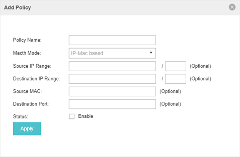
3)Configure the following parameters. When all conditions are met, the client can access the network without authentication.
|
Policy Name |
Specify a name for the policy. |
|
Match Mode |
Select the match mode for the policy. Two options are provided: URL: With this option selected, configure an URL that is allowed to be visited by the clients without authentication. IP-MAC Based: With this option selected, configure Source IP Range, Destination IP Range, Source MAC and Destination MAC to specify the specific clients and service that will follow the Free Authentication feature. |
|
URL |
Set the URL. |
|
Source IP Range |
Set the Source IP Range with the subnet and mask length of the clients. |
|
Destination IP Range |
Set the Destination IP Range with the subnet and mask length of the server. |
|
Source MAC |
Set the MAC address of client. |
|
Destination Port |
Enter the port the service uses. |
|
Status |
Check the box to enable the policy. |
4)Click Apply and the policy is successfully added.
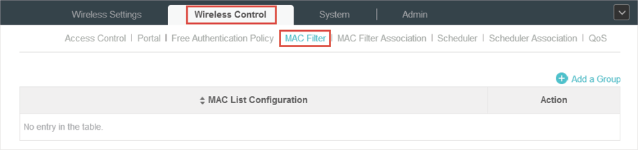
MAC filter can be used to allow or block the listed clients to access the network. Thereby it can effectively control client’s access to the wireless network.
Follow the steps below to configure MAC Filter.
1)Go to Wireless Control > MAC Filter to add MAC Filter group and group members.
Figure 5-1 MAC Filter
1. Click  and specify a name for the group.
Figure 5-2 Adding a Group
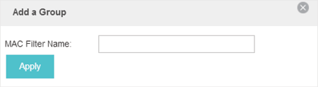
2. Click Apply and the group will be successfully added as shown below.
Figure 5-3 The Added Group
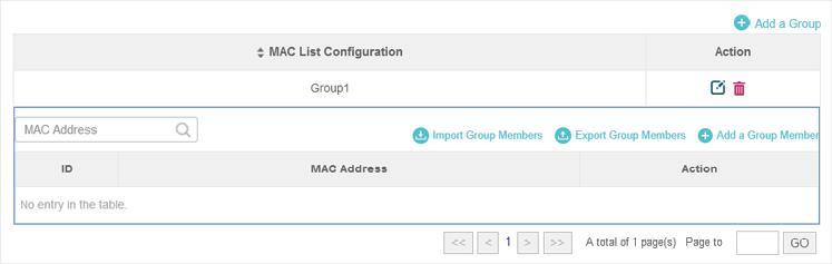
3. Click  and enter a MAC address in the format as shown below.
Figure 5-4 Adding a Group Member
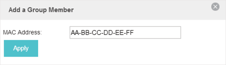
4. Click Apply to add the MAC address into the MAC filter group.
Figure 5-5 Adding the MAC Address
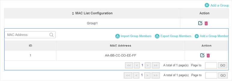
2)You can add more groups or members according to your need.
|
|
Note: You can click |
 to export the group members to a excel file and save the file on your PC. If needed, you can also click
  to import the group members to the Omada Controller.
3)Go to Wireless Control > MAC Filter Association to associate the added MAC Filter group with SSID.
Figure 5-6 MAC Filter Association

1. Check the box and click Apply to enable MAC Filtering function.
2. Select a band frequency (2.4GHz or 5GHz) and a WLAN group.
3. In the MAC Filter Name column of the specified SSID, select a MAC Filter group in the drop-down list. Then select Allow/Deny in the Action column to allow/deny the clients in the MAC Filter group to access the network.
4. Click Apply in the Setting column.
With the Scheduler, the EAPs or its’ wireless network can automatically turn on or off at the time you set. For example, you can use this feature to schedule the radio to operate only during the office working time in order to achieve security goals and reduce power consumption. You can also use the Scheduler to make clients can only access the wireless network during the time period you set in the day.
Follow the steps below to configure Scheduler.
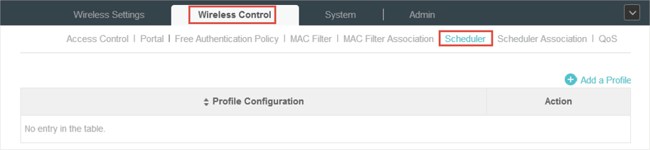
1)Go to Wireless Control > Scheduler.
Figure 6-1 Scheduler
1. Click  and specify a name for the profile.
Figure 6-2 Adding a Profile
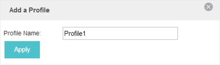
2. Click Apply and the profile will be added.
Figure 6-3 The Added Profile
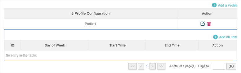
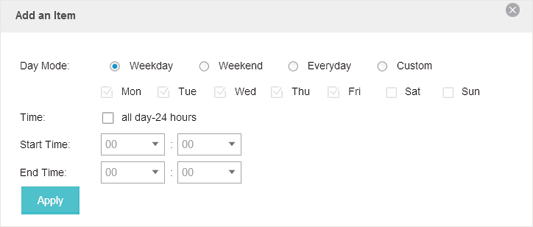
3. Click  and configure the parameters to specify a period of time.
Figure 6-4 Adding an Item
4. Click Apply and the profile is successfully added in the list.
2)Go to Wireless Control > Scheduler Association.
Figure 6-5 Scheduler Association
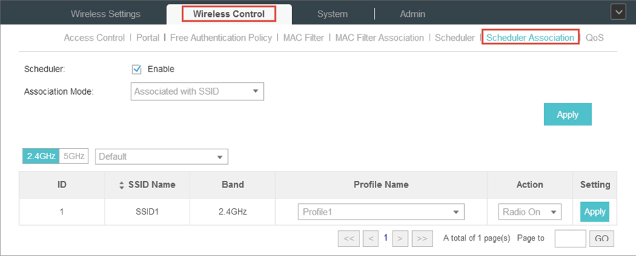
1. Check the box to enable Scheduler function.
2. Select Associated with SSID (the profile will be applied to the specific SSID on all the EAPs) or Associated with AP (the profile will be applied to all SSIDs on the specific EAP). Then click Apply.
3. Select a band frequency (2.GHz or 5GHz) and a WLAN group.
4. In the Profile Name column of the specified SSID or AP, select a profile you added before in the drop-down list. Select Radio Off/Radio On to turn on or off the wireless network during the time interval set for the profile.
5. Click Apply in the Setting column.
The Omada Controller software allows you to configure the quality of service (QoS) on the EAP device for optimal throughput and performance when handling differentiated wireless traffic, such as Voice-over-IP (VoIP), other types of audio, video, streaming media, and traditional IP data.
To configure QoS on the EAP device, you should set parameters on the transmission queues for different types of wireless traffic and specify minimum and maximum wait times (through contention windows) for transmission. In normal use, we recommend you keep the default values for the EAP devices and station EDCA (Enhanced Distributed Channel Access).
Follow the steps below to configure QoS.
1)Go to Wireless Control > QoS.
Figure 7-1 QoS
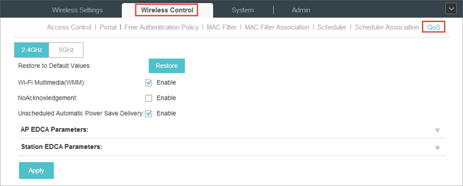
2)Enable or disable the following features.
|
Wi-Fi Multimedia (WMM) |
By default enabled. With WMM enabled, the EAP devices have the QoS function to guarantee the high priority of the transmission of audio and video packets. If 802.11n only mode is selected in 2.4GHz (or 802.11n only, 802.11ac only, or 802.11 n/ac mixed mode in 5GHz), the WMM should be enabled. If WMM is disabled, the 802.11n only mode cannot be selected in 2.4GHz (or 802.11n only, 802.11ac only, or 802.11 n/ac mixed mode in 5GHz). |
|
NoAcknowledgement |
By default disabled. You can enable this function to specify that the EAP devices should not acknowledge frames with QosNoAck. NoAcknowledgement is recommended if VoIP phones access the network through the EAP device. |
|
Unscheduled Automatic Power Save Delivery |
By default enabled. As a power management method, it can greatly improve the energy-saving capacity of clients. |
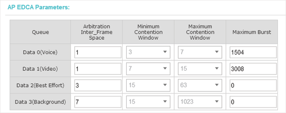
3)Click AP EDCA Parameters and the following page will appear. AP EDCA parameters affect traffic flowing from the EAP device to the client station. We recommend you use the defaults.
Figure 7-2 AP EDCA Parameters
|
Queue |
Queue displays the transmission queue. By default, the priority from high to low is Data 0, Data 1, Data 2, and Data 3. The priority may be changed if you reset the EDCA parameters. Data 0 (Voice)—Highest priority queue, minimum delay. Time-sensitive data such as VoIP and streaming media are automatically sent to this queue. Data 1 (Video)—High priority queue, minimum delay. Time-sensitive video data is automatically sent to this queue. Data 2 (Best Effort)—Medium priority queue, medium throughput and delay. Most traditional IP data is sent to this queue. Data 3 (Background)—Lowest priority queue, high throughput. Bulk data that requires maximum throughput and is not time-sensitive is sent to this queue (FTP data, for example). |
|
Arbitration Inter-Frame Space |
A wait time for data frames. The wait time is measured in slots. Valid values for Arbitration Inter-Frame Space are from 0 to 15. |
|
Minimum Contention Window |
A list to the algorithm that determines the initial random backoff wait time (window) for retry of a transmission. This value can not be higher than the value for the Maximum Contention Window. |
|
Maximum Contention Window |
The upper limit (in milliseconds) for the doubling of the random backoff value. This doubling continues until either the data frame is sent or the Maximum Contention Window size is reached. This value must be higher than the value for the Minimum Contention Window. |
|
Maximum Burst |
Maximum Burst specifies the maximum burst length allowed for packet bursts on the wireless network. A packet burst is a collection of multiple frames transmitted without header information. The decreased overhead results in higher throughput and better performance. |
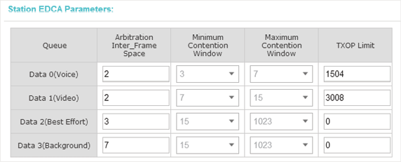
4)Click Station EDCA Parameters and the following page will appear. Station EDCA parameters affect traffic flowing from the client station to the EAP device. We recommend you use the defaults.
Figure 7-3 Station EDCA Parameters
|
Queue |
Queue displays the transmission queue. By default, the priority from high to low is Data 0, Data 1, Data 2, and Data 3. The priority may be changed if you reset the EDCA parameters. Data 0 (Voice)—Highest priority queue, minimum delay. Time-sensitive data such as VoIP and streaming media are automatically sent to this queue. Data 1 (Video)—High priority queue, minimum delay. Time-sensitive video data is automatically sent to this queue. Data 2 (Best Effort)—Medium priority queue, medium throughput and delay. Most traditional IP data is sent to this queue. Data 3 (Background)—Lowest priority queue, high throughput. Bulk data that requires maximum throughput and is not time-sensitive is sent to this queue (FTP data, for example). |
|
Arbitration Inter-Frame Space |
A wait time for data frames. The wait time is measured in slots. Valid values for Arbitration Inter-Frame Space are from 0 to 15. |
|
Minimum Contention Window |
A list to the algorithm that determines the initial random backoff wait time (window) for retry of a transmission. This value can not be higher than the value for the Maximum Contention Window. |
|
Maximum Contention Window |
The upper limit (in milliseconds) for the doubling of the random backoff value. This doubling continues until either the data frame is sent or the Maximum Contention Window size is reached. This value must be higher than the value for the Minimum Contention Window. |
|
TXOP Limit |
The TXOP Limit is a station EDCA parameter and only applies to traffic flowing from the client station to the EAP device. The Transmission Opportunity (TXOP) is an interval of time, in milliseconds, when a WME client station has the right to initiate transmissions onto the wireless medium (WM) towards the EAP device. The valid values are multiples of 32 between 0 and 8192. |
5)Click Apply.
8.1Reboot Schedule
You can reboot all the EAPs in the network periodically as needed. Follow the steps below to configure Reboot Schedule.
1)Go to System > Reboot Schedule.
Figure 8-1 Reboot Schedule
2)Check the box to enable the function.
3)Choose Daily, Weekly or Monthly in the Timing Mode drop-down list and set a specific time to reboot the EAPs.
4)Click Apply.
8.2Log Setting
Follow the steps below to choose the way to receive system logs.
1)Go to System > Log Setting.
Figure 8-2 Log Setting
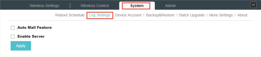
2)Check the box to choose the way to receive system logs (you can choose more than one) and click Apply. Two ways are available: Auto Mail Feature and Server.
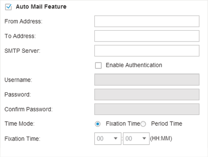
Auto Mail Feature
If Auto Mail Feature is enabled, system logs will be sent to a specified mailbox. Check the box to enable the feature and configure the parameters.
Figure 8-3 Auto Mail Feature
|
From Address |
Enter the sender's E-mail address. |
|
To Address |
Enter the receiver's E-mail address. |
|
SMTP Server |
Enter the IP address of the SMTP server. |
|
Enable Authentication |
You can check the box to enable mail server authentication. Enter the sender's mail account name and password. |
|
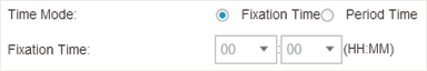
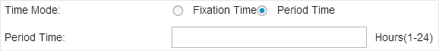
Time Mode |
Select Time Mode. System logs can be sent at specific time or time interval. |
|
Fixation Time |
If you select Fixation Time, specify a fixed time to send the system log mails. For example, 08:30 indicates that the mail will be sent at 8:30 am everyday.
|
|
Period Time |
If you select Period Time, specify a period time to regularly send the system log mail. For example, 6 indicates that the mail will be sent every six hours.
|
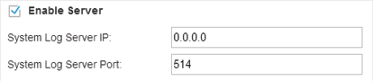
Server
If Server is enabled, system logs will be sent to a server. You can enable the feature and enter its IP address and port.
Figure 8-4 Enable Server
When the EAP devices are adopted at the first time, their username and password will become the same as those of the Omada Controller which are specified at Basic Configurations. You can specify a new username and password for the adopted EAPs in batches.
Follow the steps below to change EAP devices’ username and password.
1)Go to System > Device Account.
Figure 8-5 Device Account
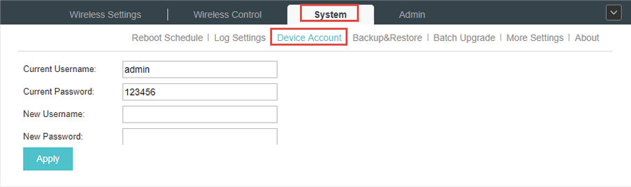
2)Specify a new username and password for the EAP devices.
3)Click Apply.
|
|
Note: The new account will be applied to EAP devices but not the Omada Controller. To change the Omada Controller’s username and password, please refer to User Account. |
8.4Backup&Restore
You can save the current configuration of the EAPs as a backup file and if necessary, and restore the configuration using the backup file. We recommend you back up the settings before upgrading the device.
Follow the steps below to backup and restore the configuration.
1)Go to System > Backup&Restore.
Figure 8-6 Backup & Restore
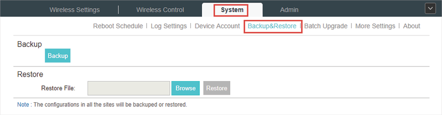
2)Click Backup and save the backup file.
3)If necessary, click Browse to locate and choose the backup file. Then click Restore to restore the configuration.
8.5Batch Upgrade
Follow the steps below to upgrade the EAP devices in batches according to their model.
1)Visit https://www.tp-link.com/en/support/download/ to download the latest firmware file of the corresponding model.
2)Go to System > Batch Upgrade.
Figure 8-7 Batch Upgrade
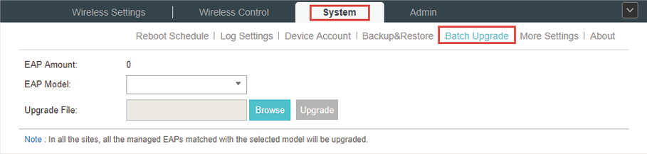
3)Select the EAP model.
4)Click Browse to locate and choose the proper firmware file for the model.
5)Click Upgrade to upgrade the device.
6)After upgrading, the device will reboot automatically.
|
|
Note: To avoid damage, please do not turn off the device while upgrading. |
8.6More Settings
You can configure the following features on the More Settings page: Historical Data Retention, LED, SSH and Management VLAN.
Go to System > More Settings.
Figure 8-8 More Settings
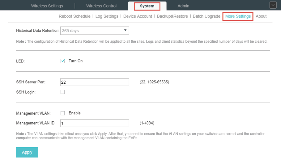
Historical Data Retention
With this feature, logs and client statistics beyond the specified number of days will be cleared. Follow the steps below to configure Historical Data Retention:
1)Select the number of days beyond which logs and client statistics will be cleared.
2)Click Apply.
LED
Follow the steps below to turn on or off the LED lights of the EAPs.
1)Check the box to change the LED light status. By default, the LED lights are on.
2)Click Apply.
SSH
You can log in to the Omada Controller via SSH. Follow the steps below to configure SSH on the Omada Controller:
1)Enter the port number of the SSH server.
2)Check the box to enable SSH Login.
3)Click Apply.
Management VLAN
Management VLAN provides a safer way for you to manage the EAP. With Management VLAN enabled, only the hosts in the management VLAN can manage the EAP. Since most hosts cannot process VLAN TAGs, connect the management host to the network via a switch, and set up correct VLAN settings for the switches on the network to ensure the communication between the host and the EAP in the management VLAN.
Follow the steps below to configure Management VLAN.
1)Check the box to enable Management VLAN.
2)Specify the Management VLAN ID.
3)Click Apply.