Configuring System Logs
CHAPTERS
4. Appendix: Default Parameters
|
|
This guide applies to: T1500G-8T v2 or above, T1500G-10PS v2 or above, T1500G-10MPS v2 or above, T1500-28PCT v3 or above, T1600G-18TS v2 or above, T1600G-28PS v3 or above, T1600G-28TS v3 or above, T1600G-52TS v3 or above, T1600G-52PS v3 or above, T1700X-16TS v3 or above, T1700G-28TQ v3 or above, T2500G-10TS v2 or above, T2600G-18TS v2 or above, T2600G-28TS v3 or above, T2600G-28MPS v3 or above, T2600G-28SQ v1 or above, T2600G-52TS v3 or above. |

The switch generates messages in response to events, faults, or errors occurred, as well as changes in configuration or other occurrences. You can check system messages for debugging and network management.
System logs can be saved in various destinations, such as the log buffer, log file or remote log servers, depending on your configuration. Logs saved in the log buffer and log file are called local logs, and logs saved in remote log servers are called remote logs. Remote logs facilitate you to remotely monitor the running status of the network.
You can set the severity level of the log messages to control the type of log messages saved in each destination.
System logs configurations include:
Configure the local logs.
Configure the remote logs.
Backing up the logs.
Viewing the log table.
Configuration Guidelines
Logs are classified into the following eight levels. Messages of levels 0 to 4 mean the functionality of the switch is affected. Please take actions according to the log message.
Table 2-1Levels of Logs
|
Severity |
Level |
Description |
Example |
|
Emergencies |
0 |
The system is unusable and you have to reboot the switch. |
Software malfunctions affect the functionality of the switch. |
|
Alerts |
1 |
Actions must be taken immediately. |
The memory utilization reaches the limit. |
|
Critical |
2 |
Cause analysis or actions must be taken immediately. |
The memory utilization reaches the warning threshold. |
|
Errors |
3 |
Error operations or unusual processing that will not affect subsequent operations but that should be noted and analyzed. |
Wrong command or password is entered. |
|
Warnings |
4 |
Conditions that may cause process failure and that should be noted. |
Error protocol packets are detected. |
|
Notifications |
5 |
Normal but significant conditions. |
The shutdown command is applied to a port. |
|
Informational |
6 |
Normal messages for your information. |
The display command is used. |
|
Debugging |
7 |
Debug-level messages that you can ignore. |
General operational information. |
2.1Using the GUI
2.1.1Configuring the Local Logs
Choose the menu MAINTENANCE > Logs > Local Logs to load the following page.
Figure 2-1 Configuring the Local Logs
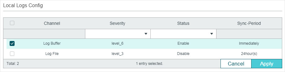
Follow these steps to configure the local logs:
1)Select your desired channel and configure the corresponding severity and status.
|
Channel |
Local logs includes 2 channels: log buffer and log file. Log buffer indicates the RAM for saving system logs. The channel is enabled by default. Information in the log buffer is displayed on the MAINTENANCE > Logs > Logs Table page. It will be lost when the switch is restarted. Log file indicates the flash sector for saving system logs. Information in the log file will not be lost after the switch is restarted and can be exported on the MAINTENANCE > Logs > Back Up Logs page. |
|
Severity |
Specify the severity level of the log messages that are saved to the selected channel. Only log messages with a severity level value that is the same or lower than this will be saved. There are eight severity levels marked from 0 to 7. A lower value indicates a higher severity. |
|
Status |
Enable or disable the channel. |
|
Sync-Periodic |
By default, the log information is saved in the log buffer immediately, and synchronized to the log file every 24 hours. If necessary, you can modify the log |
2)Click Apply.
2.1.2Configuring the Remote Logs
You can configure up to four hosts to receive the switch’s system logs. These hosts are called Log Servers. The switch will forward the log message to the servers once a log message is generated. To display the logs, the servers should run a log server software that complies with the syslog standard.
Choose the menu MAINTENANCE > Logs > Remote Logs to load the following page.
Figure 2-2 Configuring the Remote Logs
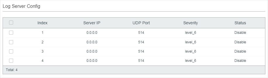
Follow these steps to configure the information of remote log servers:
1)Select an entry to enable the server, and then set the server IP address and severity.
|
Server IP |
Specify an IP address of the log server. |
|
UDP Port |
Displays the UDP port used by the server to receive the log messages. The switch uses standard port 514 to send log messages. |
|
Severity |
Specify the severity level of the log messages sent to the selected log server. Only log messages with a severity level value that is the same or lower than this will be saved. |
|
Status |
Enable or disable the log server. |
2)Click Apply.
2.1.3Backing up the Logs
Choose the menu MAINTENANCE > Logs > Back Up Logs to load the following page.
Figure 2-3 Backing up the Log File

Click Back Up Logs to save the system logs as a file on your computer. If the switch system breaks down, you can check the file for troubleshooting.
2.1.4Viewing the Log Table
Choose the menu MAINTENANCE > Logs > Log Table to load the following page.
Figure 2-4 View the Log Table
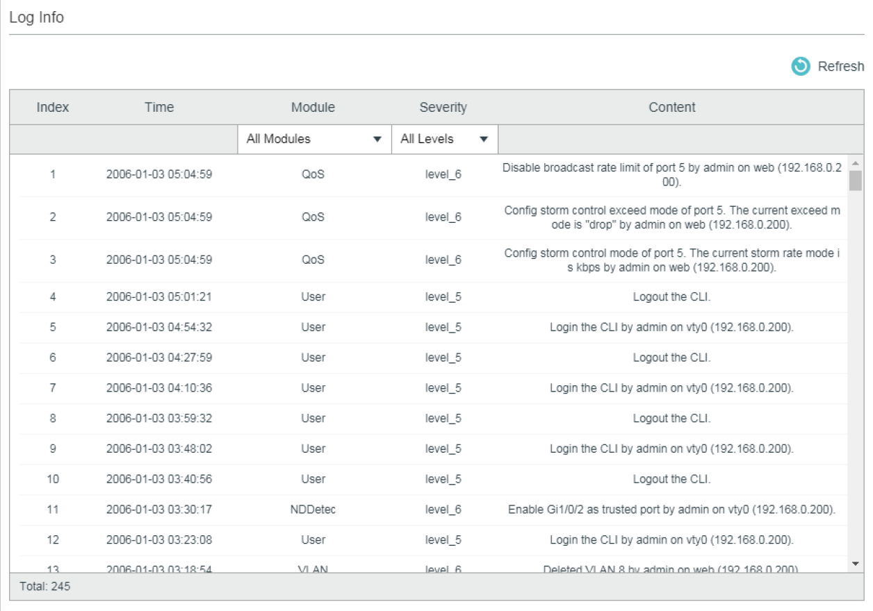
Select a module and a severity to view the corresponding log information.
|
Time |
Displays the time the log event occurred. To get the exact time when the log event occurs, you need to configure the system time on the SYSTEM > System Info > System Time Web management page. |
|
Module |
Select a module from the drop-down list to display the corresponding log information. |
|
Severity |
Select a severity level to display the log information whose severity level value is the same or smaller. |
|
Content |
Displays the detailed information of the log event. |
2.2Using the CLI
2.2.1Configuring the Local Logs
Follow these steps to configure the local logs:
|
Step 1 |
configure Enter global configuration mode. |
|
Step 2 |
logging buffer Configure the switch to save system messages in log buffer. Log buffer indicates the RAM for saving system logs. Information in the log buffer will be lost when the switch is restarted. You can view the logs with show logging buffer command. |
|
Step 3 |
logging buffer level level Specify the severity level of the log information that should be saved to the buffer. level: Enter the severity level ranging from 0 to 7. A lower value indicates a higher severity. Only log messages with a severity level value that is the same or lower than this will be saved. The default level is 6, indicating that the log information of levels 0 to 6 will be saved in the log buffer. |
|
Step 4 |
logging file flash Configure the switch to save system messages in log file. Log file indicates the flash sector for saving system logs. Information in the log file will not be lost after the switch is restarted. You can view the logs with show logging flash command. |
|
Step 5 |
logging file flash frequency { periodic periodic | immediate } Specify the frequency to synchronize the system logs in the log buffer to the flash. periodic: Specify the frequency ranging from 1 to 48 hours. By default, the synchronization process takes place every 24 hours. immediate: The system log file in the buffer will be synchronized to the flash immediately. This option means frequent operations on the flash and is not recommended. |
|
Step 6 |
logging file flash level level Specify the severity level of the log information that should be saved to the flash. level: Enter the severity level ranging from 0 to 7. A lower value indicates a higher severity. Only log messages with a severity level value that is the same or lower than this will be saved to the flash. The default level is 3, indicating that the log messages of levels 0 to 3 will be saved in the log flash. |
|
Step 7 |
show logging local-config View the configuration information of the local logs. |
|
Step 8 |
end Return to privileged EXEC mode. |
|
Step 9 |
copy running-config startup-config Save the settings in the configuration file. |
The following example shows how to configure the local logs on the switch. Save logs of levels 0 to 5 to the log buffer, and synchronize logs of levels 0 to 2 to the flash every 10 hours:
Switch#configure
Switch(config)#logging buffer
Switch(config)#logging buffer level 5
Switch(config)#logging file flash
Switch(config)#logging file flash frequency periodic 10
Switch(config)#logging file flash level 2
Switch(config)#show logging local-config
Channel Level Status Sync-Periodic
------- ----- ------ -------------
Buffer 5 enable Immediately
Flash 2 enable 10 hour(s)
Console 5 enable Immediately
Monitor 5 enable Immediately
Switch(config)#end
Switch#copy running-config startup-config
2.2.2Configuring the Remote Logs
You can configure up to four hosts to receive the switch’s system logs. These hosts are called Log Servers. The switch will forward the log message to the servers once a log message is generated. To display the logs, the servers should run a log server software that complies with the syslog standard.
Follow these steps to set the remote log:
|
Step 1 |
configure Enter global configuration mode. |
|
Step 2 |
logging host index idx host-ip level Configure a remote host to receive the switch’s system logs. The host is called Log Server. You can remotely monitor the settings and operation status of the switch through the log server. idx: Enter the index of the log server. The switch supports 4 log servers at most. host-ip: Enter the IP address of the log server. level: Specify the severity level of the log messages sent to the log server. The range is from 0 to 7, and a lower value indicates a higher severity. Only log messages with a severity level value that is the same or lower than this will be sent. The default is 6, indicating that the log information of levels 0 to 6 will be sent to the log server. |
|
Step 3 |
show logging loghost [ index ] View the configuration information of the log server. index: Enter the index of the log server to view the corresponding configuration information. If no value is specified, information of all log hosts will be displayed. |
|
Step 4 |
end Return to privileged EXEC mode. |
|
Step 5 |
copy running-config startup-config Save the settings in the configuration file. |
The following example shows how to set the remote log on the switch. Enable log server 2, set its IP address as 192.168.0.148, and allow logs of levels 0 to 5 to be sent to the server:
Switch#configure
Switch(config)# logging host index 2 192.168.0.148 5
Switch(config)# show logging loghost
Index Host-IP Severity Status
----- ------- -------- ------
1 0.0.0.0 6 disable
2 192.168.0.148 5 enable
3 0.0.0.0 6 disable
4 0.0.0.0 6 disable
Switch(config)#end
Switch#copy running-config startup-config
3.1Network Requirements
The company network manager needs to monitor network of department A for troubleshooting.
Figure 3-1 Network Topology

3.2Configuration Scheme
The network manager can configure the PC as a log server to receive the switch’s system logs. Make sure the switch and the PC are reachable to each other; configure a log server that complies with the syslog standard on the PC and set the PC as the log server.
Demonstrated with T2600G-28TS, this chapter provides configuration procedures in two ways: using the GUI and Using the CLI.
3.3Using the GUI
1)Choose the menu MAINTENANCE > Logs > Remote Logs to load the following page. Enable host 1, and set the PC’s IP address 1.1.0.1 as the server IP address, and the severity as level_5; click Apply.
Figure 3-2 Configuring the Log Server
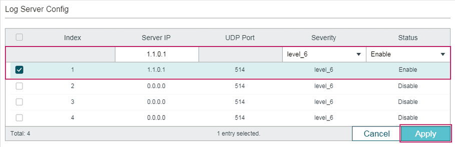
2)Click  to save the settings.
3.4Using the CLI
Configure the remote log host.
Switch#configure
Switch(config)# logging host index 1 1.1.0.1 5
Switch(config)#end
Switch#copy running-config startup-config
Verify the Configurations
Switch# show logging loghost
Index Host-IP Severity Status
----- --------- -------- --------
1 1.1.0.1 5 enable
2 0.0.0.0 6 disable
3 0.0.0.0 6 disable
4 0.0.0.0 6 disable
Default settings of maintenance are listed in the following tables.
Table 4-1Default Settings of Local Logs
|
Parameter |
Default Setting |
|
Status of Log Buffer |
Enabled |
|
Severity of Log Buffer |
Level_6 |
|
Sync-Periodic of Log Buffer |
Immediately |
|
Status of Log File |
Disabled |
|
Severity of Log File |
Level_3 |
|
Sync-Periodic of Log File |
24 hours |
Table 4-2Default Settings of Remote Logs
|
Parameter |
Default Setting |
|
Server IP |
0.0.0.0 |
|
UDP Port |
514 |
|
Severity |
Level_6 |
|
Status |
Disabled |