Configuring Spanning Tree
CHAPTERS
4. STP Security Configurations
5. Configuration Example for MSTP
6. Appendix: Default Parameters
|
|
This guide applies to: T1500G-8T v2 or above, T1500G-10PS v2 or above, T1500G-10MPS v2 or above, T1500-28PCT v3 or above, T1600G-18TS v2 or above, T1600G-28TS v3 or above, T1600G-28PS v3 or above, T1600G-52TS v3 or above, T1600G-52PS v3 or above, T1700X-16TS v3 or above, T1700G-28TQ v3 or above, T2500G-10TS v2 or above, T2600G-18TS v2 or above, T2600G-28TS v3 or above, T2600G-28MPS v3 or above, T2600G-28SQ v1 or above, T2600G-52TS v3 or above. |

1.1Overview
STP
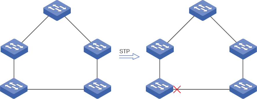
STP (Spanning Tree Protocol) is a layer 2 Protocol that prevents loops in the network. As is shown in Figure 1-1, STP helps to:
Block specific ports of the switches to build a loop-free topology.
Detect topology changes and automatically generate a new loop-free topology.
Figure 1-1 STP Function
RSTP
RSTP (Rapid Spanning Tree Protocol) provides the same features as STP. Besides, RSTP can provide much faster spanning tree convergence.
MSTP
MSTP (Multiple Spanning Tree Protocol) also provides the fast spanning tree convergence as RSTP. In addition, MSTP enables VLANs to be mapped to different spanning trees ( MST instances), and traffic in different VLANs will be transmitted along their respective paths, implementing load balancing.
1.2Basic Concepts
1.2.1STP/RSTP Concepts
Based on the networking topology below, this section will introduce some basic concepts in STP/RSTP.
Figure 1-2 STP/RSTP Topology
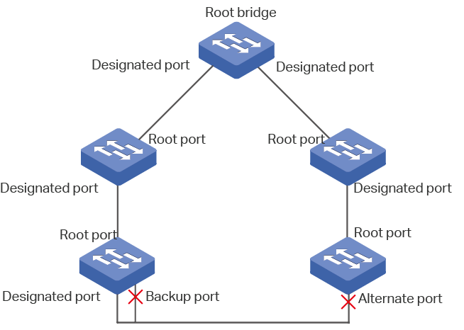
Root Bridge
The root bridge is the root of a spanning tree. The switch with te lowest bridge ID will be the root bridge, and there is only one root bridge in a spanning tree.
Bridge ID
Bridge ID is used to select the root bridge. It is composed of a 2-byte priority and a 6-byte MAC address. The priority is allowed to be configured manually on the switch, and the switch with the lowest priority value will be elected as the root bridge. If the priority of the switches are the same, the switch with the smallest MAC address will be selected as the root bridge.
Port Role
Root Port
The root port is selected on non-root bridge that can provide the lowest root path cost. There is only one root port in each non-root bridge.
Designated Port
The designated port is selected in each LAN segment that can provide the lowest root path cost from that LAN segment to the root bridge.
Alternate Port
If a port is not selected as the designated port for it receives better BPDUs from another switch, it will become an alternate port.
In RSTP/MSTP, the alternate port is the backup for the root port. It is blocked when the root port works normally. Once the root port fails, the alternate port will become the new root port.
In STP, the alternate port is always blocked.
Backup Port
If a port is not selected as the designated port for it receives better BPDUs from the switch it belongs to, it will become an backup port.
In RSTP/MSTP, the backup port is the backup for the designated port. It is blocked when the designated port works normally. Once the root port fails, the backup port will become the new designated port.
In STP, the backup port is always blocked.
Disable Port
The disconnected port with spanning tree function enabled .
Port Status
Generally, in STP, the port status includes: Blocking, Listening, Learning, Forwarding and Disabled.
Blocking
In this status, the port receives and sends BPDUs. The other packets are dropped.
Listening
In this status, the port receives and sends BPDUs. The other packets are dropped.
Learning
In this status, the port receives and sends BPDUs. It also receives the other user packets to update its MAC address table, but doesn’t forward them.
Forwarding
In this status, the port receives and sends BPDUs. It also receives the other user packets to update its MAC address table, and forwards them.
Disabled
In this status, the port is not participating in the spanning tree, and drops all the packets it receives.
In RSTP/MSTP, the port status includes: Discarding, Learning and Forwarding. The Discarding status is the grouping of STP’s Blocking, Listening and Disabled, and the Learning and Forwarding status correspond exactly to the Learning and Forwarding status specified in STP.
In TP-Link switches, the port status includes: Blocking, Learning, Forwarding and Disconnected.
Blocking
In this status, the port receives and sends BPDUs. The other packets are dropped.
Learning
In this status, the port receives and sends BPDUs. It also receives the other user packets to update its MAC address table, but doesn’t forward them.
Forwarding
In this status, the port receives and sends BPDUs. It also receives the other user packets to update its MAC address table, and forwards them.
Disconnected
In this status, the port is enabled with spanning tree function but not connected to any device.
Path Cost
The path cost reflects the link speed of the port. The smaller the value, the higher link speed the port has.
The path cost can be manually configured on each port. If not, the path cost values are automatically calculated according to the link speed as shown below:
Table 1-1The Default Path Cost Value
|
Link Speed |
Path Cost Value |
|
10Mb/s |
2,000,000 |
|
100Mb/s |
200,000 |
|
1Gb/s |
20,000 |
|
10Gb/s |
2,000 |
Root Path Cost
The root path cost is the accumulated path costs from the root bridge to the other switches. When root bridge sends its BPDU, the root path cost value is 0. When a switch receives this BPDU, the root path cost wll be increased according to the path cost of the receive port. Then it create a new BPDU with the new root file cost and forwards it to the downstream switch. The value of the accumulated root path cost increases as the BPDU spreads further.
BPDU
BPDU is a kind of packet that is used to generate and maintain the spanning tree. The BPDUs (Bridge Protocol Data Unit) contain a lot of information, like bridge ID, root path cost, port priority and so on. Switches share these information to help determine the spanning tree topology.
1.2.2MSTP Concepts
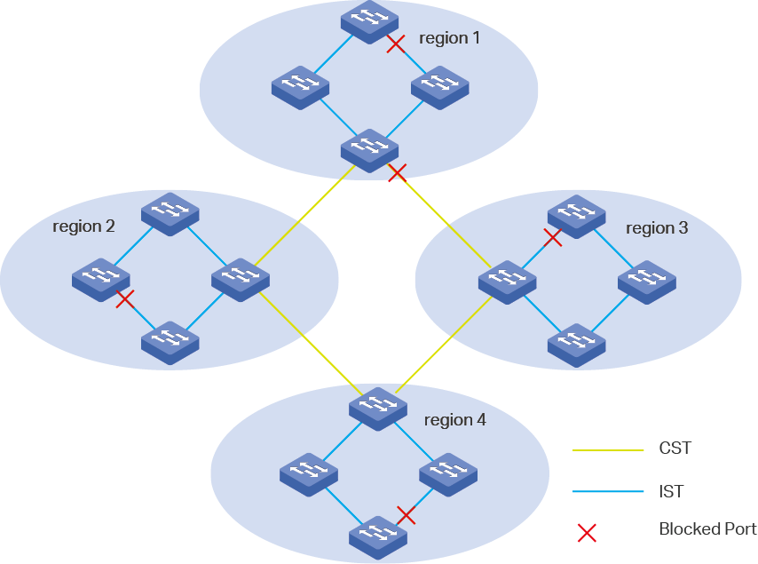
MSTP, compatible with STP and RSTP, has the same basic elements used in STP and RSTP. Based on the networking topology, this section will introduce some concepts only used in MSTP.
Figure 1-3 MSTP Topology
MST Region
An MST region consists of multiple interconnected switches. The switches with the same following characteristics are considered as in the same region:
Same region name
Same revision level
Same VLAN-Instance mapping
MST Instance
The MST instance is a spanning tree running in the MST region. Multiple MST instances can be established in one MST region and they are independent of each other. As is shown in Figure 1-4, there are three instances in a region, and each instance has its own root bridge.
Figure 1-4 MST Region
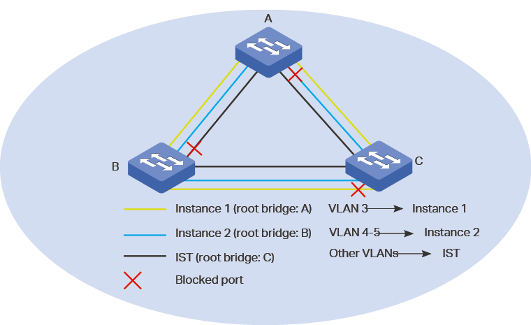
VLAN-Instance Mapping
VLAN-Instance Mapping describes the mapping relationship between VLANs and instances. Multiple VLANs can be mapped to a same instance, but one VLAN can be mapped to only one instance. As Figure 1-4 shows, VLAN 3 is mapped to instance 1, VLAN 4 and VLAN 5 are mapped to instance 2, the other VLANs are mapped to the IST.
IST
The Internal Spanning Tree (IST), which is a special MST instance with an instance ID 0. By default, all the VLANs are mapped to IST.
CST
The Common Spanning Tree (CST), that is the spanning tree connecting all MST regions. As is shown in Figure 1-3, region1-region 4 are connected by the CST.
CIST
The Common and Internal Spanning Tree (CIST), comprising IST and CST. CIST is the spanning tree that connects all the switches in the network.
1.3STP Security
STP Security prevents the loops caused by wrong configurations or BPDU attacks. It contains Loop Protect, Root Protect, BPDU Protect, BPDU Filter and TC Protect functions.
Loop Protect
Loop Protect function is used to prevent loops caused by link congestions or link failures. It is recommended to enable this function on root ports and alternate ports.
If the switch cannot receive BPDUs because of link congestions or link failures, the root port will become a designated port and the alternate port will transit to forwarding status, so loops will occur.
With Loop Protect function enabled, the port will temporarily transit to blocking state when the port does not receive BPDUs. After the link restores to normal, the port will transit to its normal state, so loops can be prevented.
Root Protect
Root Protect function is used to ensure that the desired root bridge will not lose its position. It is recommended to enable this function on the designated ports of the root bridge.
Generally, the root bridge will lose its position once receiving higher-priority BPDUs caused by wrong configurations or malicious attacks. In this case, the spanning tree will be regenerated, and traffic needed to be forwarded along high-speed links may be lead to low-speed links.
With root protect function enabled, when the port receives higher-priority BDPUs, it will temporarily transit to blocking state. After two times of forward delay, if the port does not receive any higher-priority BDPUs, it will transit to its normal state.
BPDU Protect
BPDU Protect function is used to prevent the port from receiving BPUDs. It is recommended to enable this function on edge ports.
Normally edge ports do not receive BPDUs, but if a user maliciously attacks the switch by sending BPDUs, the system automatically configures these ports as non-edge ports and regenerates the spanning tree.
With BPDU protect function enabled, the edge port will be shutdown when it receives BPDUs, and reports these cases to the administrator. Only the administrator can restore it.
BPDU Filter
BPDU filter function is to prevent BPDU flooding in the network. It is recommended to enable this function on edge ports.
If a switch receives malicious BPDUs, it forwards these BPDUs to the other switches in the network, and the spanning tree will be continuously regenerated. In this case, the switch occupies too much CPU or the protocol status of BPDUs is wrong.
With BPDU filter function enabled, the port does not forward BPDUs from the other switches.
TC Protect
TC Protect function is used to prevent the switch from frequently removing MAC address entries. It is recommended to enable this function on the ports of non-root switches.
A switch removes MAC address entries upon receiving TC-BPDUs (the packets used to announce changes in the network topology). If a user maliciously sends a large number of TC-BPDUs to a switch in a short period, the switch will be busy with removing MAC address entries, which may decrease the performance and stability of the network.
With TC protect function enabled, if the number of the received TC-BPDUs exceeds the maximum number you set in the TC threshold, the switch will not remove MAC address entries in the TC protect cycle.
To complete the STP/RSTP configuration, follow these steps:
1)Configure STP/RSTP parameters on ports.
2)Configure STP/RSTP globally.
3)Verify the STP/RSTP configurations.
Configuration Guidelines
Before configuring the spanning tree, it’s necessary to make clear the role that each switch plays in a spanning tree.
To avoid any possible network flapping caused by STP/RSTP parameter changes, it is recommended to enable STP/RSTP function globally after configuring the relevant parameters.
2.1Using the GUI
2.1.1Configuring STP/RSTP Parameters on Ports
Choose the menu L2 FEATURES > Spanning Tree > Port Config to load the following page.
Figure 2-1 Configuring STP/RSTP Parameters on Ports
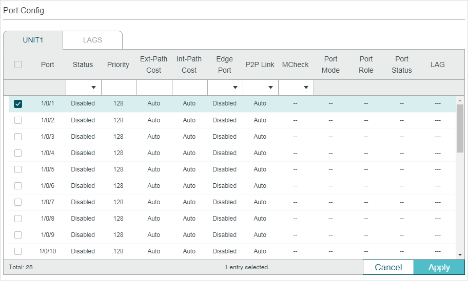
Follow these steps to configure STP/RSTP parameters on ports:
1)In the Port Config section, configure STP/RSTP parameters on ports.
|
UNIT |
Select the desired unit or LAGs. |
|
Status |
Enable or disable spanning tree function on the desired port. |
|
Priority |
Specify the Priority for the desired port. The value should be an integral multiple of 16, ranging from 0 to 240. The port with lower value has the higher priority. When the root path of the port is the same as other ports’, the switch will compare the port priorities between these port and select a root port with the highest priority. |
|
Ext-Path Cost |
Enter the value of the external path cost. The valid values are from 0 to 2000000. The default setting is Auto, which means the port calculates the external path cost automatically according to the port’s link speed. For STP/RSTP, external path cost indicates the path cost of the port in spanning tree. The port with the lowest root path cost will be elected as the root port of the switch. For MSTP, external path cost indicates the path cost of the port in CST. |
|
Int-Path Cost |
Enter the value of the internal path cost. The default setting is Auto, which means the port calculates the internal path cost automatically according to the port’s link speed. This parameter is only used in MSTP and you need not to configure it if the spanning tree mode is STP/RSTP. For MSTP, internal path cost is used to calculate the path cost in IST. The port with the lowest root path cost will be elected as the root port of the switch in IST. |
|
Edge Port |
Select Enable to set the port as an edge port. When the topology is changed, the edge port can transit its state from blocking to forwarding directly. For the quick generation of the spanning tree, it is recommended to set the ports that are connected to the end devices as edge ports. |
|
P2P Link |
Select the status of the P2P (Point-to-Point) link to which the ports are connected. During the regeneration of the spanning tree, if the port of P2P link is elected as the root port or the designated port, it can transit its state to forwarding directly. Three options are supported: Auto, Open(Force) and Closed(Force). By default, it is Auto. Auto: The switch automatically checks if the port is connected to a P2P link, then sets the status as Open or Closed. Open(Force): A port is set as the one that is connected to a P2P link. You should check the link first. Close(Force): A port is set as the one that is not connected to a P2P link. You should check the link first. |
|
MCheck |
Select whether to perform MCheck operations on the port. If a port on an RSTP-enabled/MSTP-enabled device is connected to an STP-enabled device, the port will switch to STP compatible mode and send packets in STP format. MCheck is used to switch the mode of the port back to RSTP/MSTP after the port is disconnected from the STP-enabled device. The MCheck configuration can take effect only once, after that the MCheck status of the port will switch to Disabled. |
|
Port Mode |
Displays the spanning tree mode of the port. STP: The spanning tree mode of the port is STP. RSTP: The spanning tree mode of the port is RSTP. MSTP: The spanning tree mode of the port is MSTP. |
|
Port Role |
Displays the role that the port plays in the spanning tree. Root Port: Indicates that the port is the root port in the spanning tree. It has the lowest path cost from the root bridge to this switch and is used to communicate with the root bridge. Designated Port: Indicates that the port is the designated port in the spanning tree. It has the lowest path cost from the root bridge to this physical network segment and is used to forward data for the corresponding network segment. Alternate Port: Indicates that the port is the alternate port in the spanning tree. It is the backup of the root port or master port. Backup Port: Indicates that the port is the backup port in the spanning tree. It is the backup of the designated port. Disabled: Indicates that the port is not participating in the spanning tree. |
|
Port Status |
Displays the port status. Forwarding: The port receives and sends BPDUs, and forwards user data. Learning: The port receives and sends BPDUs. It also receives user traffic, but doesn’t forward the traffic. Blocking: The port only receives and sends BPDUs. Disconnected: The port has the spanning tree function enabled but is not connected to any device. |
|
LAG |
Displays the LAG the port belongs to. |
2)Click Apply.
2.1.2Configuring STP/RSTP Globally
Choose the menu L2 FEATURES > Spanning Tree > STP Config > STP Config to load the following page.
Figure 2-2 Configuring STP/RSTP Globally
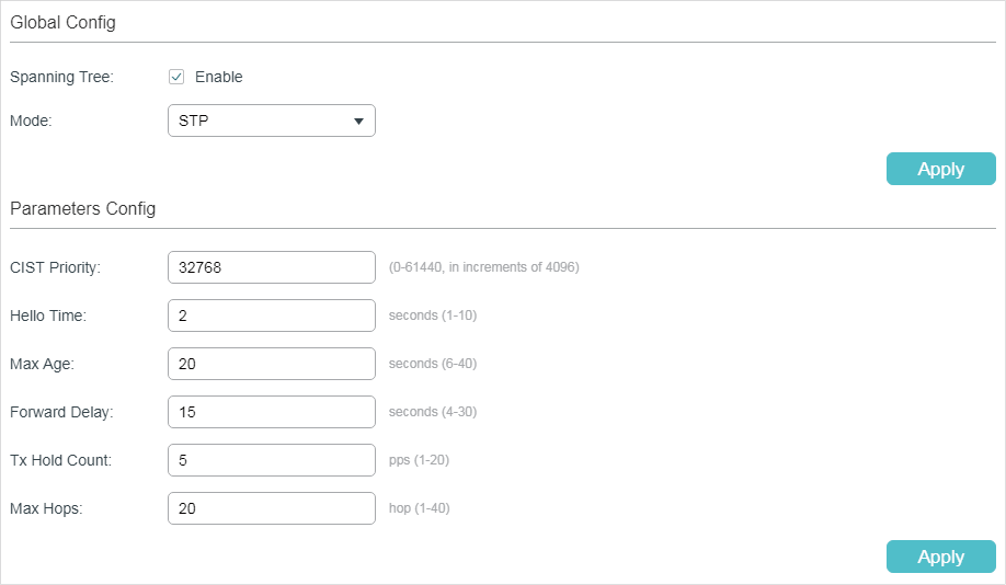
Follow these steps to configure STP/RSTP globally:
1)In the Parameters Config section, configure the global parameters of STP/RSTP and click Apply.
|
CIST Priority |
Specify the CIST priority for the switch. CIST priority is a parameter used to determine the root bridge for spanning tree. The switch with the lower value has the higher priority. In STP/RSTP, CIST priority is the priority of the switch in spanning tree. The switch with the highest priority will be elected as the root bridge. In MSTP, CISP priority is the priority of the switch in CIST. The switch with the higher priority will be elected as the root bridge in CIST. |
|
Hello Time |
Specify the interval between BPDUs’ sending. The default value is 2.The root bridge sends configuration BPDUs at an interval of Hello Time. It works with the MAX Age to test the link failures and maintain the spanning tree. |
|
Max Age |
Specify the maximum time that the switch can wait without receiving a BPDU before attempting to regenerate a new spanning tree. The default value is 2. |
|
Forward Delay |
Specify the interval between the port state transition from listening to learning. The default value is 15. It is used to prevent the network from causing temporary loops during the regeneration of spanning tree. The interval between the port state transition from learning to forwarding is also the Forward Delay. |
|
Tx Hold Count |
Specify the maximum number of BPDU that can be sent in a second. The default value is 5. |
|
Max Hops |
Specify the maximum BPDU counts that can be forwarded in a MST region. The default value is 20. A switch receives BPDU, then decrements the hop count by one and generates BPDUs with the new value. When the hop reaches zero, the switch will discard the BPDU. This value can control the scale of the spanning tree in the MST region. Note: Max Hops is a parameter configured in MSTP. You need not configure it if the spanning tree mode is STP/RSTP. |
|
|
Note: To prevent frequent network flapping, make sure that Hello Time, Forward Delay, and Max Age conform to the following formulas: 2*(Hello Time + 1) <= Max Age 2*(Forward Delay - 1) >= Max Age |

2)In the Global Config section, enable spanning tree function, choose the STP mode as STP/RSTP, and click Apply.
|
Spanning Tree |
Check the box to enable the spanning tree function globally. |
|
Mode |
Select the desired spanning tree mode as STP/RSTP on the switch. By default, it’s STP. STP: Specify the spanning tree mode as STP. RSTP: Specify the spanning tree mode as RSTP. MSTP: Specify the spanning tree mode as MSTP. |
2.1.3Verifying the STP/RSTP Configurations
Verify the STP/RSTP information of your switch after all the configurations are finished.
Choose the menu L2 FEATURES > Spanning Tree > STP Config > STP Summary to load the following page.
Figure 2-3 Verifying the STP/RSTP Configurations
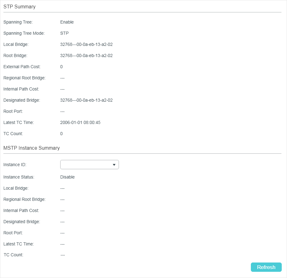
The STP Summary section shows the summary information of spanning tree :
|
Spanning Tree |
Displays the status of the spanning tree function. |
|
Spanning Tree Mode |
Displays the spanning tree mode. |
|
Local Bridge |
Displays the bridge ID of the local bridge. The local bridge is the current switch. |
|
Root Bridge |
Displays the bridge ID of the root bridge. |
|
External Path Cost |
Displays the root path cost from the switch to the root bridge. |
|
Regional Root Bridge |
It is the root bridge of IST. It is not displayed when you choose the spanning tree mode as STP/RSTP. |
|
Internal Path Cost |
The internal path cost is the root path cost from the switch to the root bridge of IST. It is not displayed when you choose the spanning tree mode as STP/RSTP. |
|
Designated Bridge |
Displays the bridge ID of the designated bridge. The designated bridge is the switch that has designated ports. |
|
Root Port |
Displays the root port of the current switch. |
|
Latest TC Time |
Displays the latest time when the topology is changed. |
|
TC Count |
Displays how many times the topology has changed. |
2.2Using the CLI
2.2.1Configuring STP/RSTP Parameters on Ports
Follow these steps to configure STP/RSTP parameters on ports:
|
Step 1 |
configure Enter global configuration mode. |
|
Step 2 |
interface {fastEthernet port | range fastEthernet port-list | gigabitEthernet port | range gigabitEthernet port-list | ten-gigabitEthernet port | range ten-gigabitEthernet port-list | port-channel port-channel-id | range port-channel port-channel-list} Enter interface configuration mode. |
|
Step 3 |
spanning-tree Enable spanning tree function for desired ports. |
|
Step 4 |
spanning-tree common-config [ port-priority pri ] [ ext-cost ext-cost ] [ portfast { enable | disable }] [ point-to-point { auto | open | close }] Configure STP/RSTP parameters on the desired port . pri: Specify the Priority for the desired port. The value should be an integral multiple of 16, ranging from 0 to 240. The default value is 128. Ports with lower values have higher priority. When the root path of the port is the same as other ports’, the switch will compare the port priorities and select a root port with the highest priority. ext-cost: Specify the value of the external path cost. The valid values are from 0 to 2000000 and the default setting is Auto, which means the port calculates the external path cost automatically according to the port’s link speed. For STP/RSTP, external path cost indicates the path cost of the port in spanning tree. The Port with the lowest root path cost will be elected as the root port of the switch. For MSTP, external path cost indicates the path cost of the port in CST. portfast { enable | disable }: Enable to set the port as an edge port. By default, it is disabled. When the topology is changed, the edge port can transit its state from blocking to forwarding directly. For the quick generation of the spanning tree, it is recommended to set the ports that are connected to the end devices as edge ports. point-to-point { auto | open | close }: Select the status of the P2P (Point-to-Point) link to which the ports are connected. During the regeneration of the spanning tree, if the port of P2P link is elected as the root port or the designated port, it can transit its state to forwarding directly. Auto indicates that the switch automatically checks if the port is connected to a P2P link, then sets the status as Open or Closed. Open is used to set the port as the one that is connected to a P2P link. Close is used to set the port as the one that is not connected to a P2P link. |
|
Step 5 |
spanning-tree mcheck (Optional) Perform MCheck operations on the port. If a port on an RSTP-enabled/MSTP-enabled device is connected to an STP-enabled device, the port will switch to STP compatible mode and send packets in STP format. MCheck is used to switch the mode of the port back to RSTP/MSTP after the port is disconnected from the STP-enabled device. The MCheck configuration can take effect only once, after that the MCheck status of the port will switch to Disabled. |
|
Step 6 |
show spanning-tree interface [ fastEthernet port | gigabitEthernet port | ten- gigabitEthernet port | port-channel lagid ] [ edge | ext-cost | int-cost | mode | p2p | priority | role | state | status ] (Optional) View the information of all ports or a specified port. port: Specify the port number. lagid: Specify the ID of the LAG. ext-cost | int-cost | mode | p2p | priority | role | state | status: Display the specified information. |
|
Step 7 |
end Return to privileged EXEC mode. |
|
Step 8 |
copy running-config startup-config Save the settings in the configuration file. |
The following example shows how to enable spanning tree function on port 1/0/3 and configure the port priority as 32 :
Switch#configure
Switch(config)#interface gigabitEthernet 1/0/3
Switch(config-if)#spanning-tree
Switch(config-if)#spanning-tree common-config port-priority 32
Switch(config-if)#show spanning-tree interface gigabitEthernet 1/0/3
Interface State Prio Ext-Cost Int-Cost Edge P2p Mode
---------- ------- ---- ------ -------- ---- --------- -----
Gi1/0/3 Enable 32 Auto Auto No No(auto) N/A
Role Status LAG
----- ------- ------
N/A LnkDwn N/A
Switch(config-if)#end
Switch#copy running-config startup-config
2.2.2Configuring Global STP/RSTP Parameters
Follow these steps to configure global STP/RSTP parameters of the switch:
|
Step 1 |
configure Enter global configuration mode. |
|
Step 2 |
spanning-tree priority pri Configure the priority of the switch. pri: Specify the priority for the switch. The valid value is from 0 to 61440, which are divisible by 4096. The priority is a parameter used to determine the root bridge for spanning tree. The switch with the lower value has the higher priority. In STP/RSTP, the value is the priority of the switch in spanning tree. The switch with the highest priority will be elected as the root bridge. In MSTP, the value is the priority of the switch in CIST. The switch with the higher priority will be elected as the root bridge in CIST. |
|
Step 3 |
spanning-tree timer {[ forward-time forward-time] [hello-time hello-time ] [ max-age max-age]} (Optional) Configure the Forward Delay, Hello Time and Max Age. forward-time: Specify the value of Forward Delay. It is the interval between the port state transition from listening to learning. The valid values are from 4 to 30 in seconds, and the default value is 15. Forward Delay is used to prevent the network from causing temporary loops during the regeneration of spanning tree. The interval between the port state transition from learning to forwarding is also the Forward Delay. hello-time: Specify the value of Hello Time. It is the interval between BPDUs’ sending. The valid values are from 1 to 10 in seconds, and the default value is 2. The root bridge sends configuration BPDUs at an interval of Hello Time. It works with the MAX Age to test the link failures and maintain the spanning tree. max-age: Specify the value of Max Age. It is the maximum time that the switch can wait without receiving a BPDU before attempting to regenerate a new spanning tree. The valid values are from 6 to 40 in seconds, and the default value is 20. |
|
Step 4 |
spanning-tree hold-count value Specify the maximum number of BPDU that can be sent in a second. value: Specify the maximum number of BPDU packets that can be sent in a second. The valid values are from 1 to 20 pps, and the default value is 5. |
|
Step 5 |
show spanning-tree bridge (Optional) View the global STP/RSTP parameters of the switch. |
|
Step 6 |
end Return to privileged EXEC mode. |
|
Step 7 |
copy running-config startup-config Save the settings in the configuration file. |
|
|
Note: To prevent frequent network flapping, make sure that Hello Time, Forward Delay, and Max Age conform to the following formulas: 2*(Hello Time + 1) <= Max Age 2*(Forward Delay - 1) >= Max Age |
This example shows how to configure the priority of the switch as 36864, the Forward Delay as 12 seconds:
Switch#configure
Switch(config)#spanning-tree priority 36864
Switch(config)#spanning-tree timer forward-time 12
Switch(config)#show spanning-tree bridge
State Mode Priority Hello-Time Fwd-Time Max-Age Hold-Count Max-Hops
------- ----- -------- ------ -------- -------- --------- --------
Enable Rstp 36864 2 12 20 5 20
Switch(config)#end
Switch#copy running-config startup-config
2.2.3Enabling STP/RSTP Globally
Follow these steps to configure the spanning tree mode as STP/RSTP, and enable spanning tree function globally:
|
Step 1 |
configure Enter global configuration mode. |
|
Step 2 |
spanning-tree mode { stp | rstp } Configure the spanning tree mode as STP/RSTP. stp: Specify the spanning tree mode as STP . rstp: Specify the spanning tree mode as RSTP . |
|
Step 3 |
spanning-tree Enable spanning tree function globally. |
|
Step 4 |
show spanning-tree active (Optional) View the active information of STP/RSTP. |
|
Step 5 |
end Return to privileged EXEC mode. |
|
Step 6 |
copy running-config startup-config Save the settings in the configuration file. |
This example shows how to enable spanning tree function, configure the spanning tree mode as RSTP and verify the configurations:
Switch#configure
Switch(config)#spanning-tree mode rstp
Switch(config)#spanning-tree
Switch(config)#show spanning-tree active
Spanning tree is enabled
Spanning-tree’s mode: RSTP (802.1w Rapid Spanning Tree Protocol)
Latest topology change time: 2006-01-02 10:04:02
Root Bridge
Priority : 32768
Address : 00-0a-eb-13-12-ba
Local bridge is the root bridge
Designated Bridge
Priority : 32768
Address : 00-0a-eb-13-12-ba
Local Bridge
Priority : 32768
Address : 00-0a-eb-13-12-ba
Interface State Prio Ext-Cost Int-Cost Edge P2p Mode
--------- -------- ---- -------- -------- ---- --------- -----
Gi1/0/16 Enable 128 200000 200000 No Yes(auto) Rstp
Gi1/0/18 Enable 128 200000 200000 No Yes(auto) Rstp
Gi1/0/20 Enable 128 200000 200000 No Yes(auto) Rstp
Role Status LAG
----- ------- ------
Desg Fwd N/A
Desg Fwd N/A
Desg Fwd N/A
Switch(config)#end
Switch#copy running-config startup-config
To complete the MSTP configuration, follow these steps:
1)Configure parameters on ports in CIST.
2)Configure the MSTP region.
3)Configure the MSTP globally.
4)Verify the MSTP configurations.
Configuration Guidelines
Before configuring the spanning tree, it’s necessary to make clear the role that each switch plays in a spanning tree.
To avoid any possible network flapping caused by MSTP parameter changes, it is recommended to enable MSTP function globally after configuring the relevant parameter.
3.1Using the GUI
3.1.1Configuring Parameters on Ports in CIST
Choose the menu L2 FEATURES > Spanning Tree > Port Config to load the following page.
Figure 3-1 Configuring the Parameters of the Ports
Follow these steps to configure parameters on ports in CIST:
1)In the Port Config section, configure the parameters on ports.
|
UNIT |
Select the desired unit or LAGs. |
|
Status |
Enable or disable spanning tree function on the desired port. |
|
Priority |
Specify the Priority for the desired port. The value should be an integral multiple of 16, ranging from 0 to 240. The port with lower value has the higher priority. When the root path of the port is the same as other ports’, the switch will compare the port priorities between these port and select a root port with the highest priority. |
|
Ext-Path Cost |
Enter the value of the external path cost. The default setting is Auto, which means the port calculates the external path cost automatically according to the port’s link speed. For STP/RSTP, external path cost indicates the path cost of the port in spanning tree. The port with the lowest root path cost will be elected as the root port of the switch. For MSTP, external path cost indicates the path cost of the port in CST. |
|
Int-Path Cost |
Enter the value of the internal path cost. The valid values are from 0 to 2000000. The default setting is Auto, which means the port calculates the internal path cost automatically according to the port’s link speed. This parameter is only used in MSTP and you need not to configure it if the spanning tree mode is STP/RSTP. For MSTP, internal path cost is used to calculate the path cost in IST. The port with the lowest root path cost will be elected as the root port of the switch in IST. |
|
Edge Port |
Select Enable to set the port as an edge port. When the topology is changed, the edge port can transit its state from blocking to forwarding directly. For the quick generation of the spanning tree, it is recommended to set the ports that are connected to the end devices as edge ports. |
|
P2P Link |
Select the status of the P2P (Point-to-Point) link to which the ports are connected. During the regeneration of the spanning tree, if the port of P2P link is elected as the root port or the designated port, it can transit its state to forwarding directly. Three options are supported: Auto, Open(Force) and Closed(Force). By default, it is Auto. Auto: The switch automatically checks if the port is connected to a P2P link, then sets the status as Open or Closed. Open(Force): A port is set as the one that is connected to a P2P link. You should check the link first. Close(Force): A port is set as the one that is not connected to a P2P link. You should check the link first. |
|
MCheck |
Select whether to perform MCheck operations on the port. If a port on an RSTP-enabled/MSTP-enabled device is connected to an STP-enabled device, the port will switch to STP compatible mode and send packets in STP format. MCheck is used to switch the mode of the port back to RSTP/MSTP after the port is disconnected from the STP-enabled device. The MCheck configuration can take effect only once, after that the MCheck status of the port will switch to Disabled. |
|
Port Mode |
Displays the spanning tree mode of the port. STP: The spanning tree mode of the port is STP. RSTP: The spanning tree mode of the port is RSTP. MSTP: The spanning tree mode of the port is MSTP. |
|
Port Role |
Displays the role that the port plays in the spanning tree. Root Port: Indicates that the port is the root port in the spanning tree. It has the lowest path cost from the root bridge to this switch and is used to communicate with the root bridge. Designated Port: Indicates that the port is the designated port in the spanning tree. It has the lowest path cost from the root bridge to this physical network segment and is used to forward data for the corresponding network segment. Master Port: Indicates the port provides the lowest root path cost from the region to the root bridge in CIST. In CIST, each region is regarded as a switch, and the master port is the root port of the corresponding region. Alternate Port: Indicates that the port is the alternate port in the spanning tree. It is the backup of the root port or master port. Backup Port: Indicates that the port is the backup port in the spanning tree. It is the backup of the designated port. Disabled: Indicates that the port is not participating in the spanning tree. |
|
Port Status |
Displays the port status. Forwarding: The port receives and sends BPDUs, and forwards user data. Learning: The port receives and sends BPDUs. It also receives user traffic, but doesn’t forward the traffic. Blocking: The port only receives and sends BPDUs. Disconnected: The port has the spanning tree function enabled but is not connected to any device. |
|
LAG |
Displays the LAG the port belongs to. |
2)Click Apply.
3.1.2Configuring the MSTP Region
Configure the region name, revision level, VLAN-Instance mapping of the switch. The switches with the same region name, the same revision level and the same VLAN-Instance mapping are considered as in the same region.
Besides, configure the priority of the switch, the priority and path cost of ports in the desired instance.
Configuring the Region Name and Revision Level
Choose the menu L2 FEATURES > Spanning Tree > MSTP Instance > Region Config to load the following page.
Figure 3-2 Configuring the Region
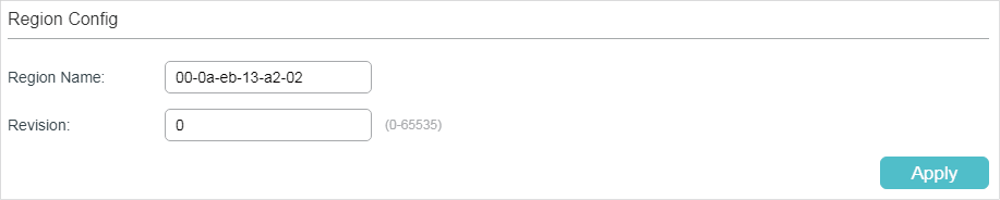
Follow these steps to create an MST region:
1)In the Region Config section, set the name and revision level to specify an MSTP region.
|
Region Name |
Configure the name for an MST region using up to 32 characters. By default, it is the MAC address of the switch. |
|
Revision |
Enter the revision level. By default, it is 0. |
2)Click Apply.
Configuring the VLAN-Instance Mapping and Switch Priority
Choose the menu L2 FEATURES > Spanning Tree > MSTP Instance > Instance Config to load the following page.
Figure 3-3 Configuring the VLAN-Instance Mapping
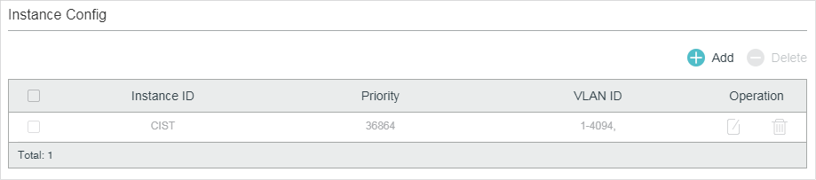
Follow these steps to map VLANs to the corresponding instance, and configure the priority of the switch in the desired instance:
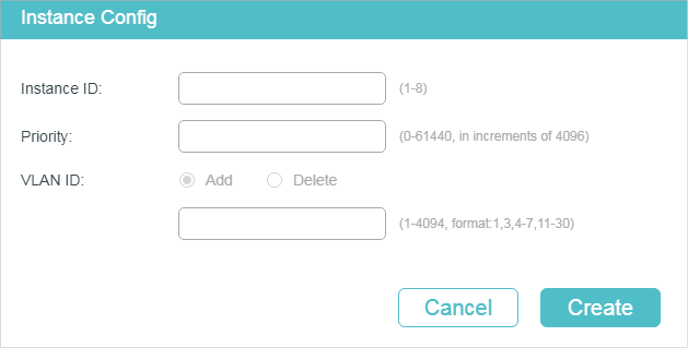
1)In the Instance Config section, click Add and enter the instance ID, Priority and corresponding VLAN ID.
Figure 3-4 Configuring the Instance
|
Instance ID |
Enter the corresponding instance ID. |
|
Priority |
Specify the priority for the switch in the corresponding instance. The value should be an integral multiple of 4096, ranging from 0 to 61440. It is used to determine the root bridge for the instance. Switches with a lower value have higher priority, and the switch with the highest priority will be elected as the root bridge in the corresponding instance. |
|
VLAN ID |
Enter the VLAN ID to map the VLAN to the desired instance or unbind the VLAN-instance mapping. |
2)Click Create.
Configuring Parameters on Ports in the Instance
Choose the menu L2 FEATURES > Spanning Tree > MSTP Instance > Instance Port Config to load the following page.
Figure 3-5 Configuring Port Parameters in the Instance
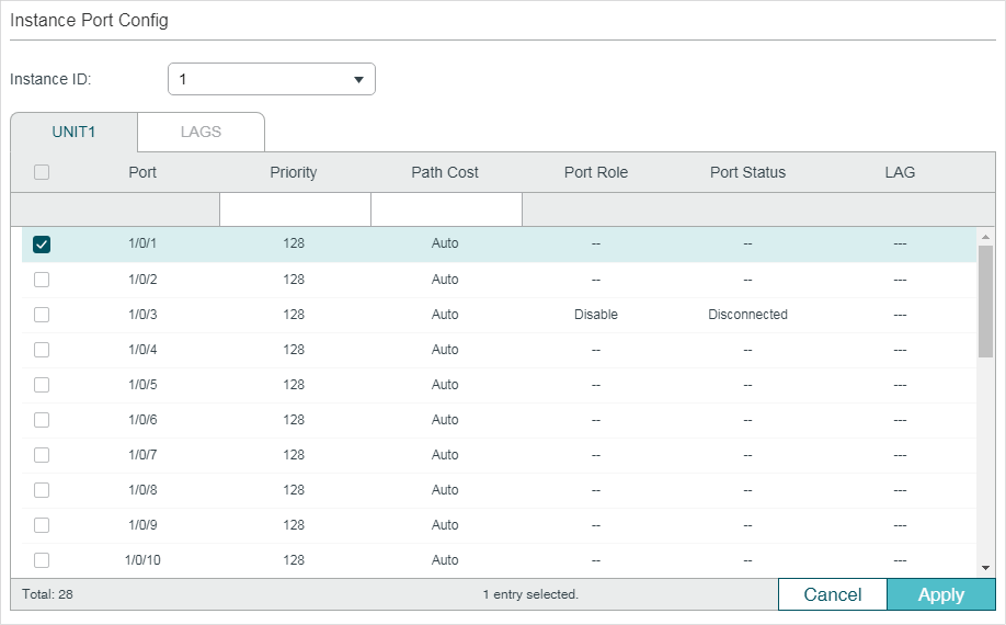
Follow these steps to configure port parameters in the instance:
1)In the Instance Port Config section, select the desired instance ID.
|
Instance ID |
Select the ID number of the instance that you want to configure. |
2)Configure port parameters in the desired instance.
|
UNIT |
Select the desired unit or LAGs for configuration. |
|
Priority |
Specify the Priority for the port in the corresponding instance. The value should be an integral multiple of 16, ranging from 0 to 240. The port with lower value has the higher priority. When the root path of the port is the same as other ports’, the switch will compare the port priorities between these ports and select a root port with the highest priority. |
|
Path Cost |
Enter the value of the path cost in the corresponding instance. The valid values are from 0 to 2000000. The default setting is Auto, which means the port calculates the external path cost automatically according to the port’s link speed. The port with the lowest root path cost will be elected as the root port of the switch. |
|
Port Role |
Displays the role that the port plays in the desired instance. Root Port: Indicates that the port is the root port in the desired instance. It has the lowest path cost from the root bridge to this switch and is used to communicate with the root bridge. Designated Port: Indicates that the port is the designated port in the desired instance. It has the lowest path cost from the root bridge to this physical network segment and is used to forward data for the corresponding network segment. Alternate Port: Indicates that the port is the alternate port in the desired instance. It is the backup of the root port or master port. Backup Port: Indicates that the port is the backup port in the desired instance. It is the backup of the designated port. Master Port: Indicates the port provides the lowest root path cost from the region to the root bridge in CIST. In CIST, each region is regarded as a switch, and the master port is the root port of the corresponding region. Disabled: Indicates that the port is not participating in the spanning tree. |
|
Port Status |
Displays the port status. Forwarding: The port receives and sends BPDUs, and forwards user traffic. Learning: The port receives and sends BPDUs. It also receives user traffic, but doesn’t forward the traffic. Blocking: The port only receives and sends BPDUs. Disconnected: The port has the spanning tree function enabled but is not connected to any device. |
|
LAG |
Displays the LAG which the port belongs to. |
3.1.3Configuring MSTP Globally
Choose the menu L2 FEATURES > Spanning Tree > STP Config > STP Config to load the following page.
Figure 3-6 Configure MSTP Function Globally
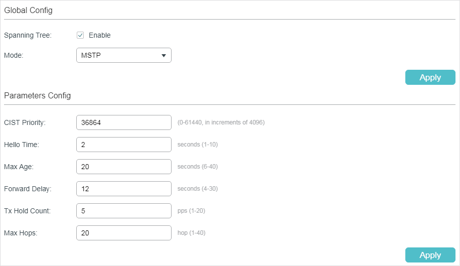
Follow these steps to configure MSTP globally:
1)In the Parameters Config section, Configure the global parameters of MSTP and click Apply.
|
CIST Priority |
Specify the CIST priority for the switch. CIST priority is a parameter used to determine the root bridge for spanning tree. The switch with the lower value has the higher priority. In STP/RSTP, CIST priority is the priority of the switch in spanning tree. The switch with the highest priority will be elected as the root bridge. In MSTP, CISP priority is the priority of the switch in CIST. The switch with the higher priority will be elected as the root bridge in CIST. |
|
Hello Time |
Specify the interval between BPDUs’ sending. The default value is 2. The root bridge sends configuration BPDUs at an interval of Hello Time. It works with the MAX Age to test the link failures and maintain the spanning tree. |
|
Max Age |
Specify the maximum time that the switch can wait without receiving a BPDU before attempting to regenerate a new spanning tree. The default calue is 20. |
|
Forward Delay |
Specify the interval between the port state transition from listening to learning. The default value is 15. It is used to prevent the network from causing temporary loops during the regeneration of spanning tree. The interval between the port state transition from learning to forwarding is also the Forward Delay. |
|
Tx Hold Count |
Specify the maximum number of BPDU that can be sent in a second. The default value is 5. |
|
Max Hops |
Specify the maximum BPDU hop counts that can be forwarded in a MST region. The default value is 20. A switch receives BPDU, then decrements the hop count by one and generates BPDUs with the new value. When the hop reaches zero, the switch will discard the BPDU. This value can control the scale of the spanning tree in the MST region. Note: Max Hops is a parameter configured in MSTP. You need not configure it if the spanning tree mode is STP/RSTP. |
|
|
Note: To prevent frequent network flapping, make sure that Hello Time, Forward Delay, and Max Age conform to the following formulas: 2*(Hello Time + 1) <= Max Age 2*(Forward Delay - 1) >= Max Age |
2)In the Global Config section, enable Spanning-Tree function and choose the STP mode as MSTP and click Apply.
|
Spanning-Tree |
Check the box to enable the spanning tree function globally. |
|
Mode |
Select the desired spanning tree mode as STP/RSTP on the switch. By default, it’s STP. STP: Specify the spanning tree mode as STP. RSTP: Specify the spanning tree mode as RSTP. MSTP: Specify the spanning tree mode as MSTP. |
3.1.4Verifying the MSTP Configurations
Choose the menu Spanning Tree > STP Config > STP Summary to load the following page.
Figure 3-7 Verifying the MSTP Configurations
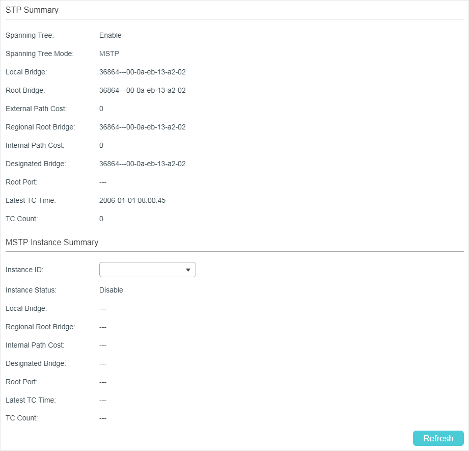
The STP Summary section shows the summary information of CIST:
|
Spanning Tree |
Displays the status of the spanning tree function. |
|
Spanning-Tree Mode |
Displays the spanning tree mode. |
|
Local Bridge |
Displays the bridge ID of the local switch. The local bridge is the current switch. |
|
Root Bridge |
Displays the bridge ID of the root bridge in CIST. |
|
External Path Cost |
Displays the external path cost. It is the root path cost from the switch to the root bridge in CIST. |
|
Regional Root Bridge |
Displays the bridge ID of the root bridge in IST. |
|
Internal Path Cost |
Displays the internal path cost. It is the root path cost from the current switch to the root bridge in IST. |
|
Designated Bridge |
Displays the bridge ID of the designated bridge in CIST. |
|
Root Port |
Displays the root port of in CIST. |
|
Latest TC Time |
Displays the latest time when the topology is changed. |
|
TC Count |
Displays how many times the topology has changed. |
The MSTP Instance Summary section shows the information in MST instances:
|
Instance ID |
Select the desired instance. |
|
Instance Status |
Displays the status of the desired instance. |
|
Local Bridge |
Displays the bridge ID of the local switch. The local bridge is the current switch. |
|
Regional Root Bridge |
Displays the bridge ID of the root bridge in the desired instance. |
|
Internal Path Cost |
Displays the internal path cost. It is the root path cost from the current switch to the regional root bridge. |
|
Designated Bridge |
Displays the bridge ID of the designated bridge in the desired instance. |
|
Root Port |
Displays the root port of the desired instance. |
|
Latest TC Time |
Displays the latest time when the topology is changed. |
|
TC Count |
Displays how many times the topology has changed. |
3.2Using the CLI
3.2.1Configuring Parameters on Ports in CIST
Follow these steps to configure the parameters of the port in CIST:
|
Step 1 |
configure Enter global configuration mode. |
|
Step 2 |
interface {fastEthernet port | range fastEthernet port-list | gigabitEthernet port | range gigabitEthernet port-list | ten-gigabitEthernet port | range ten-gigabitEthernet port-list | port-channel port-channel-id | range port-channel port-channel-list} Enter interface configuration mode. |
|
Step 3 |
spanning-tree Enable spanning tree function for the desired port. |
|
Step 4 |
spanning-tree common-config [ port-priority pri ] [ ext-cost ext-cost ] [ int-cost int-cost ][ portfast { enable | disable }] [ point-to-point { auto | open | close }] Configure the parameters on ports in CIST. pri: Specify the Priority for the desired port. The value should be an integral multiple of 16, ranging from 0 to 240. The default value is 128. Ports with lower values have higher priority. When the root path of the port is the same as other ports’, the switch will compare the port priorities and select a root port with the highest priority. ext-cost: Specify the value of the external path cost. The valid values are from 0 to 2000000 and the default setting is Auto, which means the port calculates the external path cost automatically according to the port’s link speed. For STP/RSTP, external path cost indicates the path cost of the port in spanning tree. The Port with the lowest root path cost will be elected as the root port of the switch. For MSTP, external path cost indicates the path cost of the port in CST. int-cost: Specify the value of the internal path cost. The valid values are from 0 to 2000000. The default setting is Auto, which means the port calculates the internal path cost automatically according to the port’s link speed. This parameter is only used in MSTP. For MSTP, internal path cost is used to calculate the path cost in IST. The port with the lowest root path cost will be elected as the root port of the switch in IST. portfast { enable | disable }: Enable to set the port as an edge port. By default, it is disabled. When the topology is changed, the edge port can transit its state from blocking to forwarding directly. For the quick generation of the spanning tree, it is recommended to set the ports that are connected to the end devices as edge ports. point-to-point { auto | open | close }: Select the status of the P2P (Point-to-Point) link to which the ports are connected. During the regeneration of the spanning tree, if the port of P2P link is elected as the root port or the designated port, it can transit its state to forwarding directly. Auto indicates that the switch automatically checks if the port is connected to a P2P link, then sets the status as Open or Closed. Open is used to set the port as the one that is connected to a P2P link. Close is used to set the port as the one that is not connected to a P2P link. |
|
Step 5 |
spanning-tree mcheck (Optional) Perform MCheck operations on the port. If a port on an RSTP-enabled/MSTP-enabled device is connected to an STP-enabled device, the port will switch to STP compatible mode and send packets in STP format. MCheck is used to switch the mode of the port back to RSTP/MSTP after the port is disconnected from the STP-enabled device. The MCheck configuration can take effect only once, after that the MCheck status of the port will switch to Disabled. |
|
Step 6 |
show spanning-tree interface [ fastEthernet port | gigabitEthernet port | ten-gigabitEthernet port | port-channel lagid ] [ edge | ext-cost | int-cost | mode | p2p | priority | role | state | status ] (Optional) View the information of all ports or a specified port. port: Specify the port number. lagid: Specify the ID of the LAG. ext-cost | int-cost | mode | p2p | priority | role | state | status: Display the specified information. |
|
Step 7 |
end Return to privileged EXEC mode. |
|
Step 8 |
copy running-config startup-config Save the settings in the configuration file. |
This example shows how to enable spanning tree function for port 1/0/3 and configure the port priority as 32 :
Switch#configure
Switch(config)#interface gigabitEthernet 1/0/3
Switch(config-if)#spanning-tree
Switch(config-if)#spanning-tree common-config port-priority 32
Switch(config-if)#show spanning-tree interface gigabitEthernet 1/0/3
MST-Instance 0 (CIST)
Interface State Prio Ext-Cost Int-Cost Edge P2p Mode Role Status
----------- -------- ---- -------- -------- ---- --------- ----- ------- --------
Gi1/0/3 Enable 32 Auto Auto No No(auto) N/A N/A LnkDwn
MST-Instance 5
Interface Prio Cost Role Status
----------- ------------ -------- ---------
Gi1/0/3 144 200 N/A LnkDwn
Switch(config-if)#end
Switch#copy running-config startup-config
3.2.2Configuring the MSTP Region
Configuring the MST Region
Follow these steps to configure the MST region and the priority of the switch in the instance:
|
Step 1 |
configure Enter global configuration mode. |
|
Step 2 |
spanning-tree mst instance instance-id priority pri Configure the priority of the switch in the instance. instance-id: Specify the instance ID, the valid values ranges from 1 to 8. pri: Specify the priority for the switch in the corresponding instance. The value should be an integral multiple of 4096, ranging from 0 to 61440. The default value is 32768. It is used to determine the root bridge for the instance. Switches with a lower value have higher priority, and the switch with the highest priority will be elected as the root bridge in the corresponding instance. |
|
Step 3 |
spanning-tree mst configuration Enter MST configuration mode, as to configure the VLAN-Instance mapping, region name and revision level. |
|
Step 4 |
name name Configure the region name of the region. name: Specify the region name, used to identify an MST region. The valid values are from 1 to 32 characters. |
|
Step 5 |
revision revision Configure the revision level of the region. revision: Specify the revision level of the region. The valid values are from 0 to 65535. |
|
Step 6 |
instance instance-id vlan vlan-id Configure the VLAN-Instance mapping. instance-id: Specify the Instance ID. The valid values are from 1 to 8. vlan-id: Specify the VLAN mapped to the corresponding instance. |
|
Step 7 |
show spanning-tree mst { configuration [ digest ] | instance instance-id [ interface [ fastEthernet port | gigabitEthernet port | port-channel lagid | ten-gigabitEthernet port ] ] } (Optional) View the related information of MSTP Instance. digest: Specify to display the digest calculated by instance-vlan map. instance-id: Specify the Instance ID desired to view, ranging from 1 to 8. port: Specify the port number. lagid: Specify the ID of the LAG. |
|
Step 8 |
end Return to privileged EXEC mode. |
|
Step 9 |
copy running-config startup-config Save the settings in the configuration file. |
This example shows how to create an MST region, of which the region name is R1, the revision level is 100 and VLAN 2-VLAN 6 are mapped to instance 5:
Switch#configure
Switch(config)#spanning-tree mst configuration
Switch(config-mst)#name R1
Switch(config-mst)#revision 100
Switch(config-mst)#instance 5 vlan 2-6
Switch(config-mst)#show spanning-tree mst configuration
Region-Name : R1
Revision : 100
MST-Instance Vlans-Mapped
---------------- ------------------------------------------------------------
0 1,7-4094
5 2-6,
----------------------------------------------------------------------------
Switch(config-mst)#end
Switch#copy running-config startup-config
Configuring the Parameters on Ports in Instance
Follow these steps to configure the priority and path cost of ports in the specified instance:
|
Step 1 |
configure Enter global configuration mode. |
|
Step 2 |
interface {fastEthernet port | range fastEthernet port-list | gigabitEthernet port | range gigabitEthernet port-list | ten-gigabitEthernet port | range ten-gigabitEthernet port-list | port-channel port-channel-id | range port-channel port-channel-list} Enter interface configuration mode. |
|
Step 3 |
spanning-tree mst instance instance-id {[ port-priority pri ] | [ cost cost ]} Configure the priority and path cost of ports in the specified instance. instance-id: Specify the instance ID, the valid values ranges from 1 to 8. pri: Specify the Priority for the port in the corresponding instance. The value should be an integral multiple of 16, ranging from 0 to 240. The default valueis 128. The port with lower value has the higher priority. When the root path of the port is the same as other ports’, the switch will compare the port priorities between these ports and select a root port with the highest priority. cost: Enter the value of the path cost in the corresponding instance. The valid values are from 0 to 2000000. The default setting is Auto, which means the port calculates the external path cost automatically according to the port’s link speed. The port with the lowest root path cost will be elected as the root port of the switch. |
|
Step 4 |
show spanning-tree mst { configuration [ digest ] | instance instance-id [ interface [ fastEthernet port | gigabitEthernet port | port-channel lagid | ten-gigabitEthernet port ] ] } (Optional) View the related information of MSTP Instance. digest: Specify to display the digest calculated by instance-vlan map. instance-id: Specify the Instance ID desired to view, ranging from 1 to 8. port: Specify the port number. lagid: Specify the ID of the LAG. |
|
Step 5 |
end Return to privileged EXEC mode. |
|
Step 6 |
copy running-config startup-config Save the settings in the configuration file. |
This example shows how to configure the priority as 144, the path cost as 200 of port 1/0/3 in instance 5:
Switch#configure
Switch(config)#interface gigabitEthernet 1/0/3
Switch(config-if)#spanning-tree mst instance 5 port-priority 144 cost 200
Switch(config-if)#show spanning-tree interface gigabitEthernet 1/0/3
MST-Instance 0 (CIST)
Interface State Prio Ext-Cost Int-Cost Edge P2p Mode Role Status LAG
---------- ------ ---- -------- -------- ---- --------- ----- ---- -------- ---
Gi1/0/3 Enable 32 Auto Auto No No(auto) N/A N/A LnkDwn N/A
MST-Instance 5
Interface Prio Cost Role Status LAG
----------- ------ ------ -------- --------- -------
Gi1/0/3 144 200 N/A LnkDwn N/A
Switch(config-if)#end
Switch#copy running-config startup-config
3.2.3Configuring Global MSTP Parameters
Follow these steps to configure the global MSTP parameters of the switch:
|
Step 1 |
configure Enter global configuration mode. |
|
Step 2 |
spanning-tree priority pri Configure the priority of the switch for comparison in CIST. pri: Specify the priority for the switch. The valid value is from 0 to 61440, which are divisible by 4096. The priority is a parameter used to determine the root bridge for spanning tree. The switch with the lower value has the higher priority. In STP/RSTP, the value is the priority of the switch in spanning tree. The switch with the highest priority will be elected as the root bridge. In MSTP, the value is the priority of the switch in CIST. The switch with the higher priority will be elected as the root bridge in CIST. |
|
Step 3 |
spanning-tree timer {[ forward-time forward-time ] [ hello-time hello-time ] [ max-age max-age ]} (Optional) Configure the Forward Delay, Hello Time and Max Age. forward-time: Specify the value of Forward Delay. It is the interval between the port state transition from listening to learning. The valid values are from 4 to 30 in seconds, and the default value is 15. Forward Delay is used to prevent the network from causing temporary loops during the regeneration of spanning tree. The interval between the port state transition from learning to forwarding is also the Forward Delay. hello-time: Specify the value of Hello Time. It is the interval between BPDUs’ sending. The valid values are from 1 to 10 in seconds, and the default value is 2. The root bridge sends configuration BPDUs at an interval of Hello Time. It works with the MAX Age to test the link failures and maintain the spanning tree. max-age: Specify the value of Max Age. It is the maximum time that the switch can wait without receiving a BPDU before attempting to regenerate a new spanning tree. The valid values are from 6 to 40 in seconds, and the default value is 20. |
|
Step 4 |
spanning-tree hold-count value (Optional) Specify the maximum number of BPDU that can be sent in a second. value: Specify the maximum number of BPDU packets that can be sent in a second. The valid values are from 1 to 20 pps, and the default value is 5. |
|
Step 5 |
spanning-tree max-hops value (Optional) Specify the maximum BPDU hop counts that can be forwarded in a MST region. A switch receives BPDU, then decrements the hop count by one and generates BPDUs with the new value. When the hop reaches zero, the switch will discard the BPDU. This value can control the scale of the spanning tree in the MST region. value: Specify the maximum number of hops that occur in a specific region before the BPDU is discarded. The valid values are from 1 to 40 in hop, and the default value is 20. |
|
Step 6 |
show spanning-tree bridge (Optional) View the global parameters of the switch. |
|
Step 7 |
end Return to privileged EXEC mode. |
|
Step 8 |
copy running-config startup-config Save the settings in the configuration file. |
|
|
Note: To prevent frequent network flapping, make sure that Hello Time, Forward Delay, and Max Age conform to the following formulas: 2*(Hello Time + 1) <= Max Age 2*(Forward Delay - 1) >= Max Age |
This example shows how to configure the CIST priority as 36864, the Forward Delay as 12 seconds, the Hold Count as 8 and the Max Hop as 25:
Switch#configure
Switch(config)#spanning-tree priority 36864
Switch(config-if)#spanning-tree timer forward-time 12
Switch(config-if)#spanning-tree hold-count 8
Switch(config-if)#spanning-tree max-hops 25
Switch(config-if)#show spanning-tree bridge
State Mode Priority Hello-Time Fwd-Time Max-Age Hold-Count Max-Hops
------- ------- -------- -------- -------- -------- --------- --------
Enable Mstp 36864 2 12 20 8 25
Switch(config-if)#end
Switch#copy running-config startup-config
3.2.4Enabling Spanning Tree Globally
Follow these steps to configure the spanning tree mode as MSTP and enable spanning tree function globally:
|
Step 1 |
configure Enter global configuration mode. |
|
Step 2 |
spanning-tree mode mstp Configure the spanning tree mode as MSTP. mstp: Specify the spanning tree mode as MSTP. |
|
Step 3 |
spanning-tree Enable spanning tree function globally. |
|
Step 4 |
show spanning-tree active (Optional) View the active information of MSTP. |
|
Step 5 |
end Return to privileged EXEC mode. |
|
Step 6 |
copy running-config startup-config Save the settings in the configuration file. |
This example shows how to configure the spanning tree mode as MSTP and enable spanning tree function globally :
Switch#configure
Switch(config)#spanning-tree mode mstp
Switch(config)#spanning-tree
Switch(config)#show spanning-tree active
Spanning tree is enabled
Spanning-tree’s mode: MSTP (802.1s Multiple Spanning Tree Protocol)
Latest topology change time: 2006-01-04 10:47:42
MST-Instance 0 (CIST)
Root Bridge
Priority : 32768
Address : 00-0a-eb-13-23-97
External Cost : 200000
Root Port : Gi/0/20
Designated Bridge
Priority : 32768
Address : 00-0a-eb-13-23-97
Regional Root Bridge
Priority : 36864
Address : 00-0a-eb-13-12-ba
Local bridge is the regional root bridge
Local Bridge
Priority : 36864
Address : 00-0a-eb-13-12-ba
Interface State Prio Ext-Cost Int-Cost Edge P2p Mode Role Status
---------- ------- ---- -------- -------- ---- --------- ----- ----- -------
Gi/0/16 Enable 128 200000 200000 No Yes(auto) Mstp Altn Blk
Gi/0/20 Enable 128 200000 200000 No Yes(auto) Mstp Root Fwd
MST-Instance 1
Root Bridge
Priority : 32768
Address : 00-0a-eb-13-12-ba
Local bridge is the root bridge
Designated Bridge
Priority : 32768
Address : 00-0a-eb-13-12-ba
Local Bridge
Priority : 32768
Address : 00-0a-eb-13-12-ba
Interface Prio Cost Role Status
---------- ---- -------- ------- --------
Gi/0/16 128 200000 Altn Blk
Gi/0/20 128 200000 Mstr Fwd
Switch(config)#end
Switch#copy running-config startup-config
4.1Using the GUI
Choose the menu L2 FEATURES > Spanning Tree > STP Security to load the following page.
Figure 4-1 Configuring the Port Protect
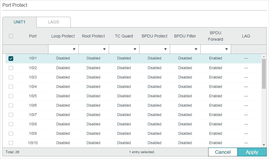
Configure the Port Protect features for the selected ports, and click Apply.
|
UNIT |
Select the desired unit or LAGs for configuration. |
|
Loop Protect |
Enable or disable Loop Protect. It is recommended to enable this function on root ports and alternate ports. When there are link congestions or link failures in the network, the switch will not receive BPDUs from the upstream device in time. Loop Protect is used to avoid loop caused by the recalculation in this situation. With Loop Protect function enabled, the port will temporarily transit to a blocking state after it does not receive BPDUs in time. |
|
Root Protect |
Enable or disable Root Protect. It is recommended to enable this function on the designated ports of the root bridge. Switches with faulty configurations may produce a higher-priority BPDUs than the root bridge’s, and this situation will cause recalculation of the spanning tree. Root Protect is used to ensure that the desired root bridge will not lose its position in the scenario above. With root protect enabled, the port will temporarily transit to blocking state when it receives higher-priority BDPUs. After two forward delays, if the port does not receive any other higher-priority BDPUs, it will transit to its normal state. |
|
TC Guard |
Enable or disable the TC Guard function. It is recommended to enable this function on the ports of non-root switches. TC Guard function is used to prevent the switch from frequently changing the MAC address table. With TC Guard function enabled, when the switch receives TC-BPDUs, it will not process the TC-BPDUs at once. The switch will wait for a fixed time and process the TC-BPDUs together after receiving the first TC-BPDU, then it will restart timing. |
|
BPDU Protect |
Enable or disable the BPDU Protect function. It is recommended to enable this function on edge ports. Edge ports in spanning tree are used to connect to the end devices and it doesn’t receive BPDUs in the normal situation. If edge ports receive BPDUs, it may be an attack. BPDU Protect is used to protect the switch from the attack talked above. With BPDU protect function enabled, the edge ports will be shutdown when they receives BPDUs, and will report these cases to the administrator. Only the administrator can restore the state of the ports. |
|
BPDU Filter |
Enable or disable BPDU Filter. It is recommended to enable this function on edge ports. With BPDU filter function enabled, the port does not forward BPDUs from the other switches. |
|
BPDU Forward |
Enable or disable BPDU Forward. This function only takes effect when the spanning tree function is disabled globally. With BPDU forward enabled, the port can still forward spanning tree BPDUs when the spanning tree function is disabled. |
4.2Using the CLI
4.2.1Configuring the STP Security
Follow these steps to configure the Root protect feature, BPDU protect feature and BPDU filter feature for ports:
|
Step 1 |
configure Enter global configuration mode. |
|
Step 2 |
interface {fastEthernet port | range fastEthernet port-list | gigabitEthernet port | range gigabitEthernet port-list | ten-gigabitEthernet port | range ten-gigabitEthernet port-list | port-channel port-channel-id | range port-channel port-channel-list} Enter interface configuration mode. |
|
Step 3 |
spanning-tree guard loop (Optional) Enable Loop Protect. It is recommended to enable this function on root ports and alternate ports. When there are link congestions or link failures in the network, the switch will not receive BPDUs from the upstream device in time. Loop Protect is used to avoid loop caused by the recalculation in this situation. With Loop Protect function enabled, the port will temporarily transit to a blocking state after it does not receive BPDUs in time. |
|
Step 4 |
spanning-tree guard root (Optional) Enable Root Protect. It is recommended to enable this function on the designated ports of the root bridge. Switches with faulty configurations may produce a higher-priority BPDUs than the root bridge’s, and this situation will cause recalculation of the spanning tree. Root Protect is used to ensure that the desired root bridge will not lose its position in the scenario above. With root protect enabled, the port will temporarily transit to blocking state when it receives higher-priority BDPUs. After two forward delays, if the port does not receive any other higher-priority BDPUs, it will transit to its normal state. |
|
Step 5 |
spanning-tree guard tc (Optional) Enable the TC Guard function. It is recommended to enable this function on the ports of non-root switches. TC Guard function is used to prevent the switch from frequently changing the MAC address table. With TC Guard function enabled, when the switch receives TC-BPDUs, it will not process the TC-BPDUs at once. The switch will wait for a fixed time and process the TC-BPDUs together after receiving the first TC-BPDU, then it will restart timing. |
|
Step 6 |
spanning-tree bpduguard (Optional) Enable the BPDU Protect function. It is recommended to enable this function on edge ports. Edge ports in spanning tree are used to connect to the end devices and it doesn’t receive BPDUs in the normal situation. If edge ports receive BPDUs, it may be an attack. BPDU Protect is used to protect the switch from the attack talked above. With BPDU protect function enabled, the edge ports will be shutdown when they receives BPDUs, and will report these cases to the administrator. Only the administrator can restore the state of the ports. |
|
Step 7 |
spanning-tree bpdufilter (Optional) Enable or disable BPDU Filter. It is recommended to enable this function on edge ports. With BPDU filter function enabled, the port does not forward BPDUs from the other switches. |
|
Step 8 |
spanning-tree bpduflood (Optional) Enable BPDU Forward. This function only takes effect when the spanning tree function is disabled globally. By default, it is enabled. With BPDU forward enabled, the port can still forward spanning tree BPDUs when the spanning tree function is disabled. |
|
Step 9 |
show spanning-tree interface-security [ fastEthernet port | gigabitEthernet port | ten-gigabitEthernet port | port-channel port-channel-id ] [ bpdufilter | bpduguard | bpduflood | loop | root | tc ] (Optional) View the protect inforamtion of ports. port: Specify the port number. lagid: Specify the ID of the LAG. |
|
Step 10 |
end Return to privileged EXEC mode. |
|
Step 11 |
copy running-config startup-config Save the settings in the configuration file. |
This example shows how to enable Loop Protect, Root Protect, BPDU Filter and BPDU Protect functions on port 1/0/3:
Switch#configure
Switch(config)#interface gigabitEthernet 1/0/3
Switch(config-if)#spanning-tree guard loop
Switch(config-if)#spanning-tree guard root
Switch(config-if)#spanning-tree bpdufilter
Switch(config-if)#spanning-tree bpduguard
Switch(config-if)#show spanning-tree interface-security gigabitEthernet 1/0/3
Interface BPDU-Filter BPDU-Guard Loop-Protect Root-Protect TC-Protect BPDU-Flood
---------- ----------- ----------- ------------ ------------ --------- ---------
Gi1/0/3 Enable Enable Enable Enable Disable Enable
Switch(config-if)#end
Switch#copy running-config startup-config
5Configuration Example for MSTP
MSTP, backwards-compatible with STP and RSTP, can map VLANs to instances to implement load-balancing, thus providing a more flexible method in network management. Here we take the MSTP configuration as an example.
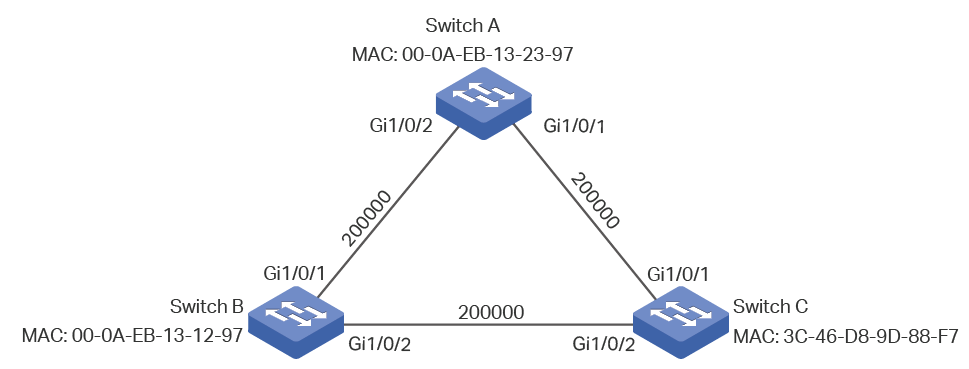
5.1Network Requirements
As shown in figure 5-1, the network consists of three switches. Traffic in VLAN 101-VLAN 106 is transmitted in this network. The link speed between the switches is 100Mb/s (the default path cost of the port is 200000).
It is required that traffic in VLAN 101 - VLAN 103 and traffic in VLAN 104 - VLAN 106 should be transmitted along different paths.
Figure 5-1 Network Topology
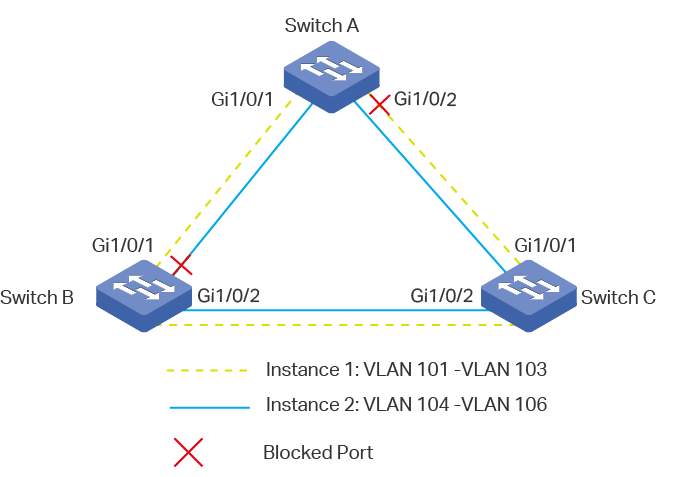
5.2Configuration Scheme
To meet this requirement, you are suggested to configure MSTP function on the switches. Map the VLANs to different instances to ensure traffic can be transmitted along the respective instance.
Here we configure two instances to meet the requirement, as is shown below:
Figure 5-2 VLAN-Instance Mapping
The overview of configuration is as follows:
1)Enable MSTP function globally in all the switches.
2)Enable Spanning Tree function on the ports in each switch.
3)Configure Switch A, Switch B and Switch C in the same region. Configure the region name as 1, and the revision level as 100. Map VLAN 101 - VLAN 103 to instance 1 and VLAN 104 - VLAN 106 to instance 2.
4)Configure the priority of Switch B as 0 to set it as the root bridge in instance 1; configure the priority of Switch C as 0 to set it as the root bridge in instance 2.
5)Configure the path cost to block the specified ports. For instance 1, set the path cost of port 1/0/1 of Switch A to be greater than the default path cost (200000); for instance 2, set the path cost of port 1/0/2 of Switch B to be greater than the default path cost (200000). After this configuration, port 1/0/2 of Switch A in instance 1 and port 1/0/1 of Switch B in instance 2 will be blocked for they cannot be neither root port nor designated port.
|
|
Note: Please configure MSTP for each switch first and then connect them together to avoid broadcast storm. |
5.3Using the GUI
Configurations for Switch A
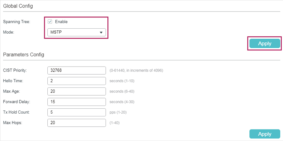
1)Choose the menu L2 FEATURES > Spanning Tree > STP Config > STP Config to load the following page. Enable MSTP function globally, here we leave the values of the other global parameters as default settings. Click Apply.
Figure 5-3 Configure the Global MSTP Parameters of the Switch
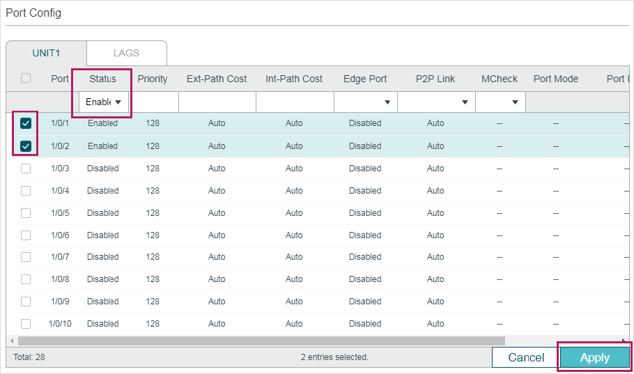
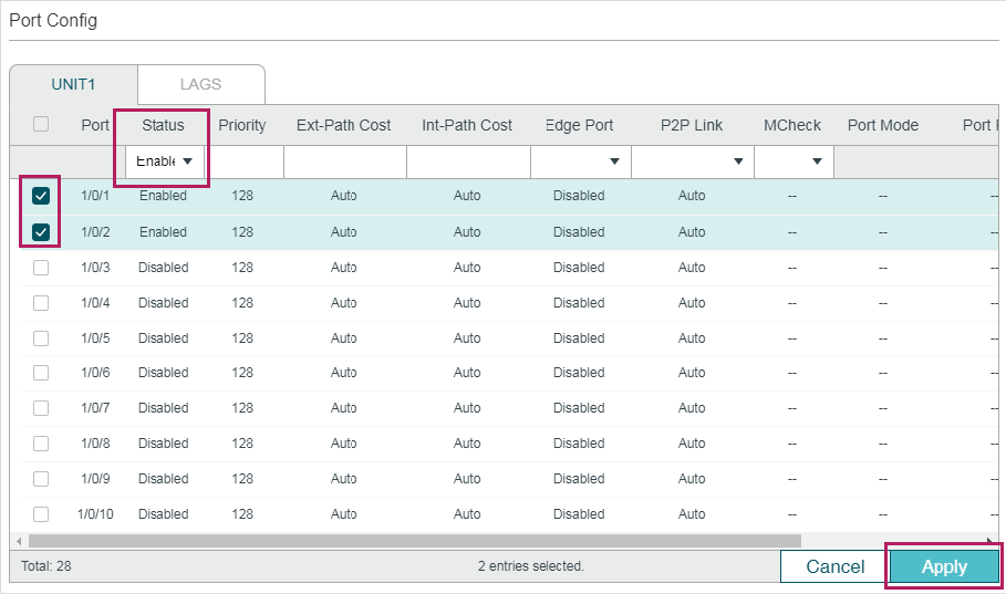
2)Choose the menu L2 FEATURES > Spanning Tree > STP Config > Port Config to load the following page. Enable spanning tree function on port 1/0/1 and port 1/0/2. Here we leave the values of the other parameters as default settings. Click Apply.
Figure 5-4 Enable Spanning Tree Function on Ports
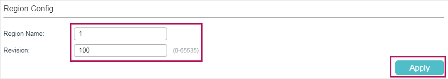
3)Choose the menu L2 FEATURES > Spanning Tree > MSTP Instance > Region Config to load the following page. Set the region name as 1 and the revision level as 100. Click Apply.
Figure 5-5 Configuring the MST Region
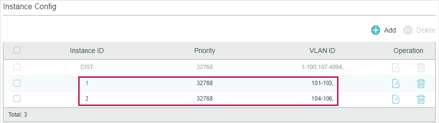
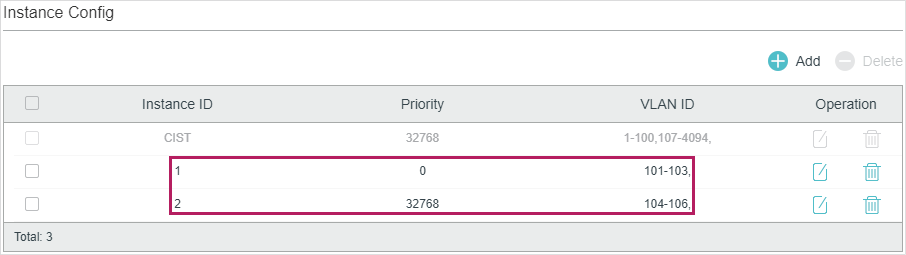
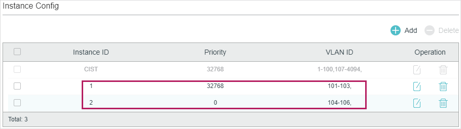
4)Choose the menu L2 FEATURES > Spanning Tree > MSTP Instance > Instance Config. Click Add, map VLAN101-VLAN103 to instance 1 and set the priority as 32768; map VLAN104-VLAN106 to instance 2 and set the priority as 32768. Click Create.
Figure 5-6 Configuring the VLAN-Instance Mapping
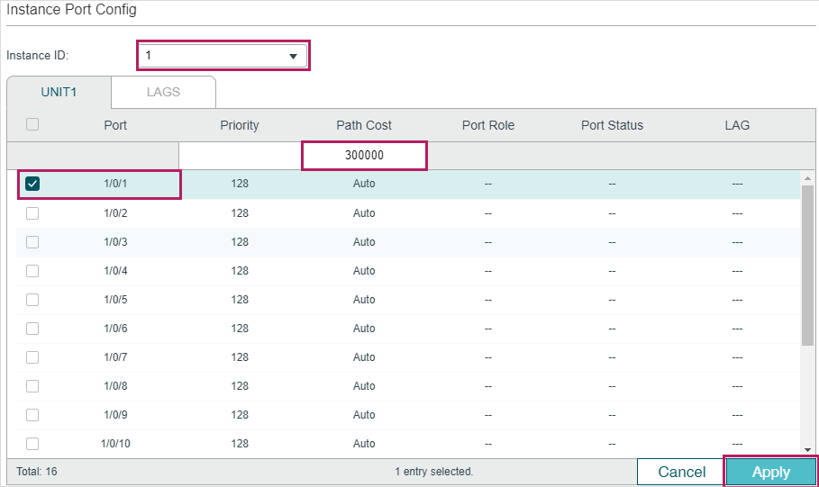
5)Choose the menu L2 FEATURES > Spanning Tree > MSTP Instance > Instance Port Config to load the following page. Set the path cost of port 1/0/1 in instance 1 as 300000 so that port 1/0/1 of switch C can be selected as the designated port.
Figure 5-7 Configure the Path Cost of Port 1/0/1 In Instance 1
6)Click  to save the settings.
Configurations for Switch B
1)Choose the menu L2 FEATURES > Spanning Tree > STP Config > STP Config to load the following page. Enable MSTP function globally, here we leave the values of the other global parameters as default settings. Click Apply.
Figure 5-8 Configure the Global MSTP Parameters of the Switch
2)Choose the menu L2 FEATURES > Spanning Tree > STP Config > Port Config to load the following page. Enable the spanning tree function on port 1/0/1 and port 1/0/2. Here we leave the values of the other parameters as default settings. Click Apply.
Figure 5-9 Enable Spanning Tree Function on Ports
3)Choose the menu L2 FEATURES > Spanning Tree > MSTP Instance > Region Config to load the following page. Set the region name as 1 and the revision level as 100. Click Apply.
Figure 5-10 Configuring the Region
4)Choose the menu L2 FEATURES > Spanning Tree > MSTP Instance > Instance Config. Map VLAN101-VLAN103 to instance 1 and set the Priority as 0; map VLAN104-VLAN106 to instance 2 and set the priority as 32768. Click Create.
Figure 5-11 Configuring the VLAN-Instance Mapping
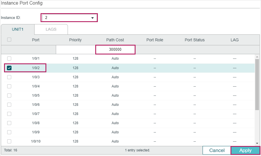
5)Choose the menu L2 FEATURES > Spanning Tree > MSTP Instance > Instance Port Config to load the following page. Set the path cost of port 1/0/2 in instance 2 as 300000 so that port 1/0/1 of switch A can be selected as the designated port.
Figure 5-12 Configure the Path Cost of Port 1/0/2 in Instance 2
6)Click  to save the settings.
Configurations for Switch C
1)Choose the menu L2 FEATURES > Spanning Tree > STP Config > STP Config to load the following page. Enable MSTP function globally, here we leave the values of the other global parameters as default settings. Click Apply.
Figure 5-13 Configure the Global MSTP Parameters of the Switch
2)Choose the menu L2 FEATURES > Spanning Tree > STP Config > Port Config to load the following page. Enable the spanning tree function on port 1/0/1 and port 1/0/2. Here we leave the values of the other parameters as default settings. Click Apply.
Figure 5-14 Enable Spanning Tree Function on Ports
3)Choose the menu Spanning Tree > MSTP Instance > Region Config to load the following page. Set the region name as 1 and the revision level as 100. Click Apply.
Figure 5-15 Configuring the Region
4)Choose the menu L2 FEATURES > Spanning Tree > MSTP Instance > Instance Config. Click Add, map VLAN101-VLAN103 to instance 1 and set the priority as 32768; map VLAN104-VLAN106 to instance 2 and set the priority as 0. Click Create.
Figure 5-16 Configuring the VLAN-Instance Mapping
5)Click  to save the settings.
5.4Using the CLI
Configurations for Switch A
1)Configure the spanning tree mode as MSTP, then enable spanning tree function globally.
Switch#configure
Switch(config)#spanning-tree mode mstp
Switch(config)#spanning-tree
2)Enable the spanning tree function on port 1/0/1 and port 1/0/2, and specify the path cost of port 1/0/1 in instance 1 as 300000.
Switch(config)#interface gigabitEthernet 1/0/1
Switch(config-if)#spanning-tree
Switch(config-if)#spanning-tree mst instance 1 cost 300000
Switch(config-if)#exit
Switch(config)#interface gigabitEthernet 1/0/2
Switch(config-if)#spanning-tree
Switch(config-if)#exit
3)Configure the region name as 1, the revision number as 100; map VLAN101-VLAN103 to instance 1; map VLAN104-VLAN106 to instance 2:
Switch(config)#spanning-tree mst configuration
Switch(config-mst)#name 1
Switch(config-mst)#revision 100
Switch(config-mst)#instance 1 vlan 101-103
Switch(config-mst)#instance 2 vlan 104-106
Switch(config-mst)#end
Switch#copy running-config startup-config
Configurations for Switch B
1)Configure the spanning tree mode as MSTP, then enable spanning tree function globally.
Switch#configure
Switch(config)#spanning-tree mode mstp
Switch(config)#spanning-tree
2)Enable the spanning tree function on port 1/0/1 and port 1/0/2, and specify the path cost of port 1/0/2 in instance 2 as 300000.
Switch(config)#interface gigabitEthernet 1/0/2
Switch(config-if)#spanning-tree
Switch(config-if)#spanning-tree mst instance 2 cost 300000
Switch(config-if)#exit
Switch(config)#interface gigabitEthernet 1/0/1
Switch(config-if)#spanning-tree
Switch(config-if)#exit
3)Configure the region name as 1, the revision number as 100; map VLAN101-VLAN103 to instance 1; map VLAN104-VLAN106 to instance 2; configure the priority of Switch B in instance 1 as 0 to set it as the root bridge in instance 1:
Switch(config)#spanning-tree mst configuration
Switch(config-mst)#name 1
Switch(config-mst)#revision 100
Switch(config-mst)#instance 1 vlan 101-103
Switch(config-mst)#instance 2 vlan 104-106
Switch(config-mst)#exit
Switch(config)#spanning-tree mst instance 1 priority 0
Switch(config)#end
Switch#copy running-config startup-config
Configurations for Switch C
1)Configure the spanning tree mode as MSTP, then enable spanning tree function globally.
Switch#configure
Switch(config)#spanning-tree mode mstp
Switch(config)#spanning-tree
2)Enable the spanning tree function on port 1/0/1 and port 1/0/2.
Switch(config)#interface range gigabitEthernet 1/0/1-2
Switch(config-if-range)#spanning-tree
Switch(config-if-range)#exit
3)Configure the region name as 1, the revision number as 100; map VLAN101-VLAN103 to instance 1; map VLAN104-VLAN106 to instance 2; configure the priority of Switch C in instance 2 as 0 to set it as the root bridge in instance 2:
Switch(config)#spanning-tree mst configuration
Switch(config-mst)#name 1
Switch(config-mst)#revision 100
Switch(config-mst)#instance 1 vlan 101-103
Switch(config-mst)#instance 2 vlan 104-106
Switch(config-mst)#exit
Switch(config)#spanning-tree mst instance 2 priority 0
Switch(config)#end
Switch#copy running-config startup-config
Verify the Configurations
Switch A
Verify the configurations of Switch A in instance 1:
Switch(config)#show spanning-tree mst instance 1
MST-Instance 1
Root Bridge
Priority : 0
Address : 00-0a-eb-13-12-ba
Internal Cost : 400000
Root Port : 1
Designated Bridge
Priority : 0
Address : 00-0a-eb-13-12-ba
Local Bridge
Priority : 32768
Address : 00-0a-eb-13-23-97
Interface Prio Cost Role Status LAG
--------- ---- -------- ------ ----- ----
Gi1/0/1 128 300000 Root Fwd N/A
Gi1/0/2 128 200000 Altn Blk N/A
Verify the configurations of Switch A in instance 2:
Switch(config)#show spanning-tree mst instance 2
MST-Instance 2
Root Bridge
Priority : 0
Address : 3c-46-d8-9d-88-f7
Internal Cost : 200000
Root Port : 2
Designated Bridge
Priority : 0
Address : 3c-46-d8-9d-88-f7
Local Bridge
Priority : 32768
Address : 00-0a-eb-13-23-97
Interface Prio Cost Role Status LAG
--------- ---- -------- ------- ------- ----
Gi1/0/1 128 200000 Desg Fwd N/A
Gi1/0/2 128 200000 Root Fwd N/A
Switch B
Verify the configurations of Switch B in instance 1:
Switch(config)#show spanning-tree mst instance 1
MST-Instance 1
Root Bridge
Priority : 0
Address : 00-0a-eb-13-12-ba
Local bridge is the root bridge
Designated Bridge
Priority : 0
Address : 00-0a-eb-13-12-ba
Local Bridge
Priority : 0
Address : 00-0a-eb-13-12-ba
Interface Prio Cost Role Status
---------- ---- -------- ------- --------
Gi1/0/1 128 200000 Desg Fwd
Gi1/0/2 128 200000 Desg Fwd
Verify the configurations of Switch B in instance 2:
Switch(config)#show spanning-tree mst instance 2
MST-Instance 2
Root Bridge
Priority : 0
Address : 3c-46-d8-9d-88-f7
Internal Cost : 400000
Root Port : 2
Designated Bridge
Priority : 0
Address : 3c-46-d8-9d-88-f7
Local Bridge
Priority : 32768
Address : 00-0a-eb-13-12-ba
Interface Prio Cost Role Status
--------- ---- -------- ------- -------
Gi1/0/1 128 200000 Altn Blk
Gi1/0/2 128 300000 Root Fwd
Switch C
Verify the configurations of Switch C in instance 1:
Switch(config)#show spanning-tree mst instance 1
MST-Instance 1
Root Bridge
Priority : 0
Address : 00-0a-eb-13-12-ba
Internal Cost : 200000
Root Port : 2
Designated Bridge
Priority : 0
Address : 00-0a-eb-13-12-ba
Local Bridge
Priority : 32768
Address : 3c-46-d8-9d-88-f7
Interface Prio Cost Role Status
---------- ------ -------- --------- ----------
Gi1/0/1 128 200000 Desg Fwd
Gi1/0/2 128 200000 Root Fwd
Verify the configurations of Switch C in instance 2:
Switch(config)#show spanning-tree mst instance 2
MST-Instance 2
Root Bridge
Priority : 0
Address : 3c-46-d8-9d-88-f7
Local bridge is the root bridge
Designated Bridge
Priority : 0
Address : 3c-46-d8-9d-88-f7
Local Bridge
Priority : 0
Address : 3c-46-d8-9d-88-f7
Interface Prio Cost Role Status
----------- ------ --------- ------- ----------
Gi1/0/1 128 200000 Desg Fwd
Gi1/0/2 128 200000 Desg Fwd
Default settings of the Spanning Tree feature are listed in the following table.
Table 6-1Default Settings of the Global Parameters
|
Parameter |
Default Setting |
|
Spanning-tree |
Disabled |
|
Mode |
STP |
|
CIST Priority |
32768 |
|
Hello Time |
2 seconds |
|
Max Age |
20 seconds |
|
Forward Delay |
15 seconds |
|
Tx Hold Count |
5 pps |
|
Max Hops |
20 hops |
Table 6-2Default Settings of the Port Parameters
|
Parameter |
Default Setting |
|
Status |
Disabled |
|
Priority |
128 |
|
Ext-Path Cost |
Auto |
|
In-Path Cost |
Auto |
|
Edge Port |
Disabled |
|
P2P Link |
Auto |
|
MCheck |
------ |
Table 6-3Default Settings of the MSTP Instance
|
Parameter |
Default Setting |
|
Status |
Disabled |
|
Revision Level |
0 |
|
Priority |
32768 |
|
Port Priority |
128 |
|
Path Cost |
Auto |
Table 6-4Default Settings of the STP Security
|
Parameter |
Default Setting |
|
Loop Protect |
Disabled |
|
Root Protect |
Disabled |
|
TC Guard |
Disabled |
|
BPDU Protect |
Disabled |
|
BPDU Filter |
Disabled |
|
BPDU Forward |
Enabled |