Configuring Network
CHAPTERS
|
|
This guide applies to: TL-R470T+ v6 or above, TL-R480T+ v9 or above, TL-R600VPN v4 or above, TL-ER5120 v3 or above, TL-ER6020 v2 or above, TL-ER6120 v3 or above |

The Network module provides basic router functions, including WAN connection, DHCP service, VLAN, IPTV service and more.
1.1Supported Features
WAN
The router can provide a maximum of four WAN ports. Each WAN port has its own internet connection, providing link backup and load balancing.
LAN
For LAN configuration, you can configure the LAN IP address and DHCP (Dynamic Host Configuration Protocol) server. With its DHCP server enabled, the router can automatically assign IP addresses to hosts in the LAN.
IPTV
IPTV services is based on the Internet protocol, rather than through traditional satellite signal or cable transmission.
The router supports three kinds of IPTV configuration according to your ISP:
IPTV based on IGMP.
IPTV in Bridge mode.
IPTV in Custom mode.
MAC
You can change the default MAC address of the WAN port or LAN port according to your needs.
Switch
The router supports some basic switch port management functions, like Port Mirror, Rate Control, Flow Control and Port Negotiation, to help you to monitor the traffic and manage the network effectively.
VLAN
The router supports 802.1Q VLAN, which can divide the LAN into multiple VLANs, helping to manage the network more effectively.
IPv6
You can set up an IPv6 internet connection if your ISP provides IPv6 service.
You can configure at most four WAN ports. Each WAN port can have its own WAN connection, providing link backup and load balancing.
To complete WAN configuration, follow these steps:
1)Configure the number of WAN ports.
2)Configure the WAN connection.
2.1Configuring the Number of WAN Ports
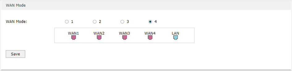
Choose the menu Network > WAN > WAN Mode to load the following page.
Figure 2-1 Configuring the WAN Mode
|
WAN Mode |
Specify the number of WAN ports. 1: Configure physical interface 1 as WAN1. 2: Configure physical interface 1 and interface 2 as WAN1 and WAN2 respectively. 3: Configure physical interface 1, interface 2 and interface3 as WAN1, WAN2 and WAN3 respectively. 4: Configure physical interface 1, interface 2, interface 3 and interface 4 as WAN1, WAN2, WAN3 and WAN4 respectively. |
|
|
Note: •When a WAN port is added, a port-related tab is automatically added; when a WAN port is deleted, the port-related tab is automatically deleted. •The router will reboot after switching the WAN mode. |

2.2Configuring the WAN Connection
The router supports six connection types: Static IP, Dynamic IP, PPPoE, L2TP, PPTP and BigPond Cable, you can choose one according to the service provided by your ISP.
Static IP: If your ISP provides you with a fixed IP address and the corresponding parameters, choose Static IP.
Dynamic IP: If your ISP automatically assigns the IP address and the corresponding parameters, choose Dynamic IP.
PPPoE: If your ISP provides you with a PPPoE account, choose PPPoE.
L2TP: If your ISP provides you with an L2TP account, choose L2TP.
PPTP: If your ISP provides you with a PPTP account, choose PPTP.
BigPond Cable: If your ISP provides you with a BigPond Cable account, choose BigPond Cable. BigPond Cable is only available for Australian users.
Configuring the Dynamic IP
Choose the menu Network > WAN > WAN to load the following page.
Figure 2-2 Configuring the Dynamic IP
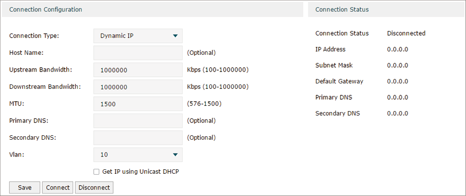
In the Connection Configuration section, select the connection type as Dynamic IP. Enter the corresponding parameters and click Save.
|
Connection Type |
Choose the connection type as Dynamic IP if your ISP automatically assigns the IP address. |
|
Host Name |
Optional. Enter a name for the router. It is null by default. |
|
Upstream Bandwidth |
Specify the upstream bandwidth of the WAN port. The value configured here is the upper limit of the “Maximum Upstream Bandwidth” on Transmission > Bandwidth Control > Bandwidth Control page, to make “Bandwidth Control” take effect, please ensure this parameter is set correctly. |
|
Downstream Bandwidth |
Specify the downstream bandwidth of the WAN port. The value configured here is the lower limit of the “Maximum Downstream Bandwidth” on Transmission > Bandwidth Control > Bandwidth Control page, to make “Bandwidth Control” take effect, please ensure this parameter is set correctly. |
|
MTU |
Specify the MTU (Maximum Transmission Unit) of the WAN port. MTU is the maximum data unit transmitted in the physical network. When Dynamic IP is selected, MTU can be set in the range of 576-1500 bytes. The default value is 1500. |
|
Primary/Secondary DNS |
Optional. Enter the IP address of the DNS server provided by your ISP. |
|
VLAN |
Add the WAN port to a VLAN. Generally, you don’t need to manually configure it unless required by your ISP. By default, the WAN port is automatically assigned to a VLAN, and the egress rule of the VLAN is UNTAG, so the packets are transmitted by the WAN port without VLAN tags. If you want the WAN port to transmit packets with VLAN tag, you need to create the corresponding VLAN first and configure its egress rule as TAG, then manually add the WAN port to that VLAN. To create VLANs, go to Network > VLAN > VLAN. Note: When using the IPTV function, either in Bridge mode or Custom mode, the router will automatically create corresponding VLANs after you finished the configuration, and add port 1 (WAN 1) to the VLANs. Users cannot then manually select the VLAN that WAN 1 belongs to. |
|
Get IP using Unicast DHCP |
The broadcasting requirement may not be supported by a few ISPs. Select this option if you can not get the IP address from your ISP even with a normal network connection. This option is not required generally. |
|
Connect/Disconnect |
Click the button to active/terminate the connection. |
Configuring the Static IP
Choose the menu Network > WAN > WAN to load the following page.
Figure 2-3 Configuring the Static IP
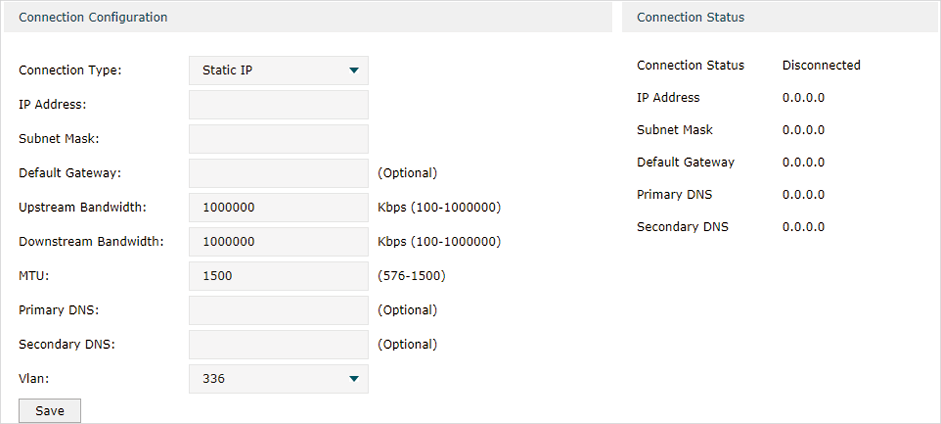
In Connection Configuration section, select the connection type as Static IP. Enter the corresponding parameters and click Save.
|
Connection Type |
Choose the connection type as Static IP if your ISP has offered you a fixed IP address. |
|
IP Address |
Enter the IP address provided by your ISP. |
|
Subnet Mask |
Enter the subnet mask provided by your ISP. |
|
Default Gateway |
Enter the default gateway provided by your ISP. |
|
Upstream Bandwidth |
Specify the downstream bandwidth of the WAN port. The value configured here is the lower limit of the “Maximum Downstream Bandwidth” on Transmission > Bandwidth Control > Bandwidth Control page, to make “Bandwidth Control” take effect, please ensure this parameter is set correctly. |
|
Downstream Bandwidth |
Specify the downstream bandwidth of the WAN port. The value configured here is the lower limit of the “Maximum Downstream Bandwidth” on Transmission > Bandwidth Control > Bandwidth Control page, to make “Bandwidth Control” take effect, please ensure this parameter is set correctly. |
|
MTU |
Specify the MTU (Maximum Transmission Unit) of the WAN port. MTU is the maximum data unit transmitted in the physical network. When Static IP is selected, MTU can be set in the range of 576-1500 bytes. The default value is 1500. |
|
Primary/Secondary DNS |
Optional. Enter the IP address of the DNS server provided by your ISP. |
|
VLAN |
Add the WAN port to a VLAN. Generally, you don’t need to manually configure it unless required by your ISP. By default, the WAN port is automatically assigned to a VLAN, and the egress rule of the VLAN is UNTAG, so the packets are transmitted by the WAN port without VLAN tags. If you want the WAN port to transmit packets with VLAN tag, you need to create the corresponding VLAN first and configure its egress rule as TAG, then manually add the WAN port to that VLAN. To create VLANs, go to Network > VLAN > VLAN. Note: When using the IPTV function, either in Bridge mode or Custom mode, the router will automatically create corresponding VLANs after you finished the configuration, and add port 1 (WAN1) to the VLANs. Users cannot then manually select the VLAN that WAN 1 belongs to. |
Configuring the PPPoE
Choose the menu Network > WAN > WAN to load the following page.
Figure 2-4 Configuring the PPPoE
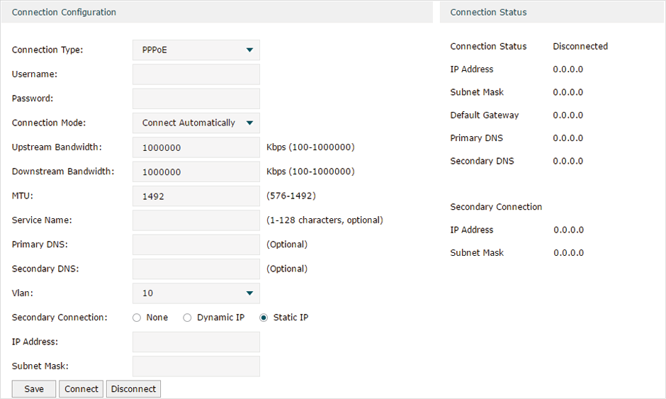
In the Connection Configuration section, select the connection type as PPPoE. Enter the corresponding parameters and click Save.
|
Connection Type |
Choose the connection type as PPPoE if your ISP provides you with a PPPoE account. |
|
Username |
Enter the PPPoE username provided by your ISP. |
|
Password |
Enter the PPPoE password provided by your ISP. |
|
Connection Mode |
Choose the connection mode, including Connect Automatically, Connect Manually and Time-Based. Connect Automatically: The router will activate the connection automatically when the router reboots or the connection is down. Connect Manually: You can manually activate or terminate the connection. Time-Based: During the specified period, the router will automatically activate the connection. |
|
Time |
Choose the effective time range when the Connection Mode is chosen as Time-Based. To create the time range, go to Preferences > Time Range > Time Range. |
|
Upstream Bandwidth |
Specify the upstream bandwidth of the WAN port. The value configured here is the upper limit of the “Maximum Upstream Bandwidth” on Transmission > Bandwidth Control > Bandwidth Control page, to make “Bandwidth Control” take effect, please ensure this parameter is set correctly. |
|
Downstream Bandwidth |
Specify the downstream bandwidth of the WAN port. The value configured here is the lower limit of the “Maximum Downstream Bandwidth” on Transmission > Bandwidth Control > Bandwidth Control page, to make “Bandwidth Control” take effect, please ensure this parameter is set correctly. |
|
MTU |
Specify the MTU (Maximum Transmission Unit) of the WAN port. MTU is the maximum data unit transmitted in the physical network. When PPPoE is selected, MTU can be set in the range of 576-1492 bytes. The default value is 1492. |
|
Service Name |
Optional. Enter the service name. This parameter is not required unless provided by your ISP. It is null by default. |
|
Primary/Secondary DNS |
Optional. Enter the IP address of the DNS server provided by your ISP. |
|
VLAN |
Add the WAN port to a VLAN. Generally, you don’t need to manually configure it unless required by your ISP. By default, the WAN port is automatically assigned to a VLAN, and the egress rule of the VLAN is UNTAG, so the packets are transmitted by the WAN port without VLAN tags. If you want the WAN port to transmit packets with VLAN tag, you need to create the corresponding VLAN first and configure its egress rule as TAG, then manually add the WAN port to that VLAN. To create VLANs, go to Network > VLAN > VLAN. Note: When using the IPTV function, either in Bridge mode or Custom mode, the router will automatically create corresponding VLANs after you finished the configuration, and add port 1 (WAN 1) to the VLANs. Users cannot then manually select the VLAN that WAN 1 belongs to. |
|
Secondary Connection |
Secondary connection is required by some ISPs. Select the connection type required by your ISP. None: Select this if the secondary connection is not required by your ISP. Dynamic IP: Select this if your ISP automatically assigns the IP address and subnet mask for the secondary connection. Static IP: Select this if your ISP provides you with a fixed IP address and subnet mask for the secondary connection. |
|
Connect/Disconnect |
Click the button to active/terminate the connection. |
Configuring the L2TP
Choose the menu Network > WAN > WAN to load the following page.
Figure 2-5 Configuring the L2TP
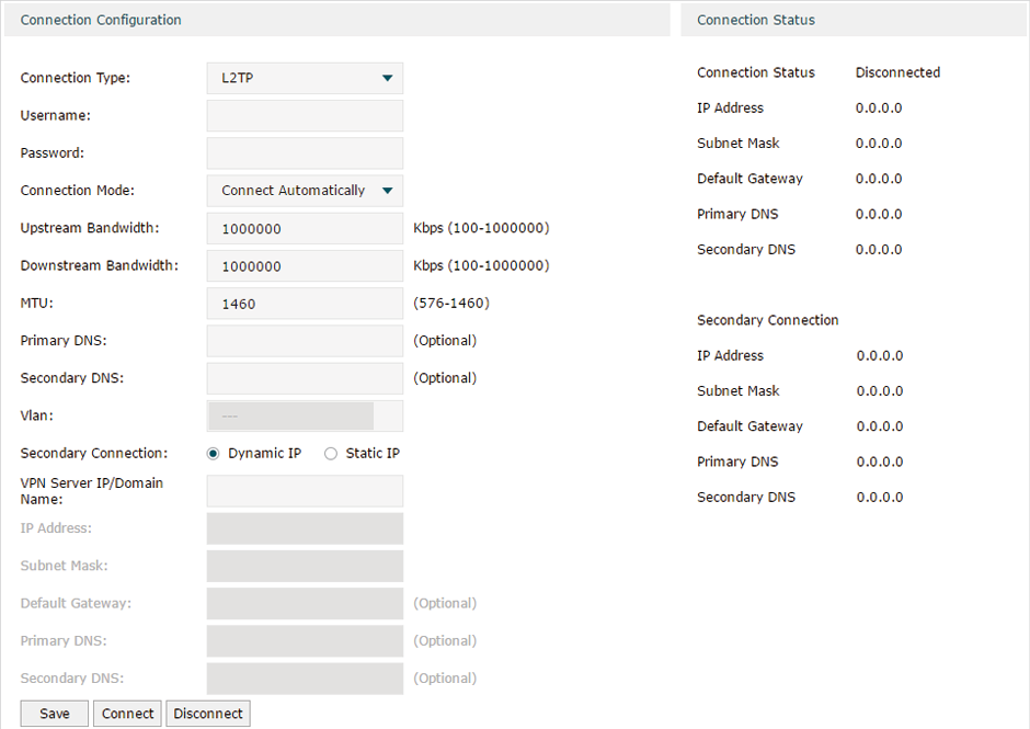
In the Connection Configuration section, select the connection type as L2TP. Enter the corresponding parameters and click Save.
|
Connection Type |
Choose the connection type as L2TP if your ISP provides you with an L2TP account. |
|
Username |
Enter the L2TP username provided by your ISP. |
|
Password |
Enter the L2TP password provided by your ISP. |
|
Connection Mode |
Choose the connection mode, including Connect Automatically, Connect Manually and Time-Based. Connect Automatically: The router will activate the connection automatically when the router reboots or the connection is down. Connect Manually: You can manually activate or terminate the connection. Time-Based: During the specified period, the router will automatically activate the connection. |
|
Time |
Choose the effective time range when the Connection Mode is chosen as Time-Based. To create the time range, go to Preferences > Time Range > Time Range. |
|
Upstream Bandwidth |
Specify the upstream bandwidth of the WAN port. The value configured here is the upper limit of the “Maximum Upstream Bandwidth” on Transmission > Bandwidth Control > Bandwidth Control page, to make “Bandwidth Control” take effect, please ensure this parameter is set correctly. |
|
Downstream Bandwidth |
Specify the downstream bandwidth of the WAN port. The value configured here is the lower limit of the “Maximum Downstream Bandwidth” on Transmission > Bandwidth Control > Bandwidth Control page, to make “Bandwidth Control” take effect, please ensure this parameter is set correctly. |
|
MTU |
Specify the MTU (Maximum Transmission Unit) of the WAN port. MTU is the maximum data unit transmitted in the physical network. When L2TP is selected, MTU can be set in the range of 576-1460 bytes. The default value is 1460. |
|
Primary/Secondary DNS |
Optional. Enter the IP address of the DNS server provided by your ISP. |
|
VLAN |
Add the WAN port to a VLAN. Generally, you don’t need to manually configure it unless required by your ISP. By default, the WAN port is automatically assigned to a VLAN, and the egress rule of the VLAN is UNTAG, so the packets are transmitted by the WAN port without VLAN tags. If you want the WAN port to transmit packets with VLAN tag, you need to create the corresponding VLAN first and configure its egress rule as TAG, then manually add the WAN port to that VLAN. To create VLANs, go to Network > VLAN > VLAN. Note: When using the IPTV function, either in Bridge mode or Custom mode, the router will automatically create corresponding VLANs after you finished the configuration, and add port 1 (WAN 1) to the VLANs. Users cannot then manually select the VLAN that WAN 1 belongs to. |
|
Secondary Connection |
Select the secondary connection type provided by your ISP The secondary connection is required for L2TP connection. The router will get some necessary information after the secondary connection succeeded. These information will be used in the L2TP connection process. |
|
VPN Server/Domain Name |
Enter the VPN Server/Domain Name provided by your ISP. |
|
IP Address |
Enter the IP address provided by your ISP for the secondary connection. |
|
Subnet Mask |
Enter the subnet mask provided by your ISP for the secondary connection. |
|
Default Gateway |
Enter the default gateway provided by your ISP for the secondary connection. |
|
Primary/Secondary DNS |
Enter the primary/secondary DNS provided by your ISP for the secondary connection. |
|
Connect/Disconnect |
Click the button to active/terminate the connection. |
Configuring the PPTP
Choose the menu Network > WAN > WAN to load the following page.
Figure 2-6 Configuring the PPTP
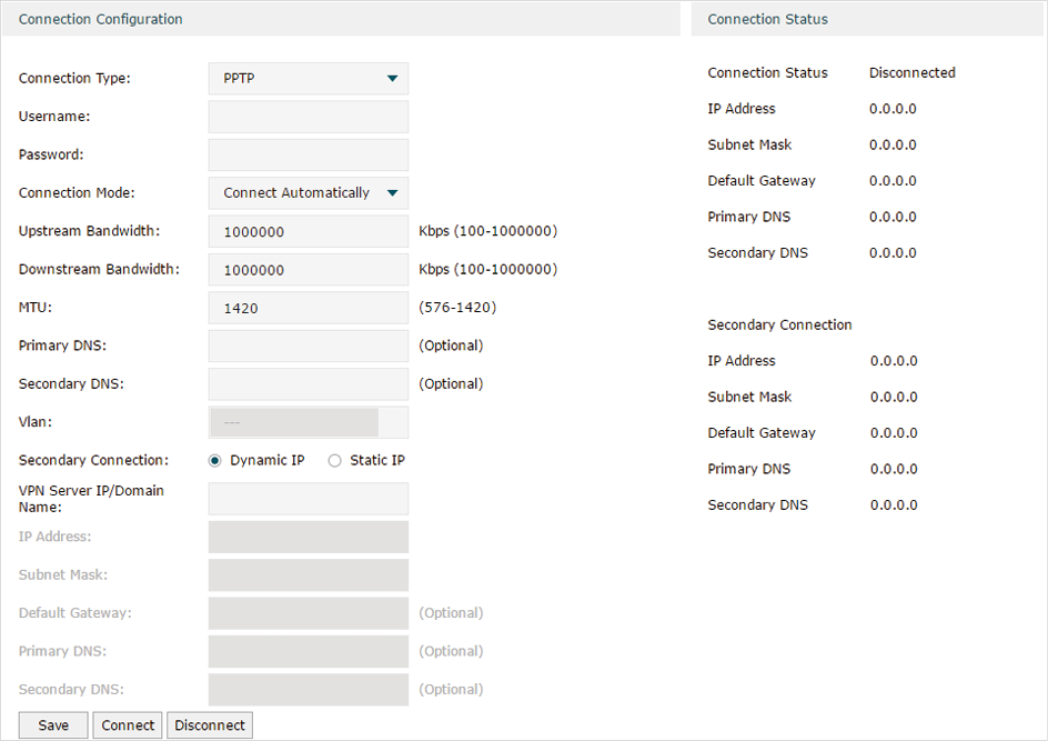
In Connection Configuration section, select the connection type as PPTP. Enter the corresponding parameters and click Save.
|
Connection Type |
Choose the connection type as PPTP if your ISP provides you with a PPTP account. |
|
Username |
Enter the PPTP username provided by your ISP. |
|
Password |
Enter the PPTP password provided by your ISP. |
|
Connection Mode |
Choose the connection mode, including Connect Automatically, Connect Manually and Time-Based. Connect Automatically: The router will activate the connection automatically when the router reboots or the connection is down. Connect Manually: You can manually activate or terminate the connection. Time-Based: During the specified period, the router will automatically activate the connection. |
|
Time |
Choose the effective time range when the Connection Mode is chosen as Time-Based. To create the time range, go to Preferences > Time Range > Time Range. |
|
Upstream Bandwidth |
Specify the upstream bandwidth of the WAN port. The value configured here is the upper limit of the “Maximum Upstream Bandwidth” on Transmission > Bandwidth Control > Bandwidth Control page, to make “Bandwidth Control” take effect, please ensure this parameter is set correctly. |
|
Downstream Bandwidth |
Specify the downstream bandwidth of the WAN port. The value configured here is the lower limit of the “Maximum Downstream Bandwidth” on Transmission > Bandwidth Control > Bandwidth Control page, to make “Bandwidth Control” take effect, please ensure this parameter is set correctly. |
|
MTU |
Specify the MTU (Maximum Transmission Unit) of the WAN port. MTU is the maximum data unit transmitted in the physical network. When PPTP is selected, MTU can be set in the range of 576-1420 bytes. The default value is 1420. |
|
Primary/Secondary DNS |
Optional. Enter the IP address of the DNS server provided by your ISP. |
|
VLAN |
Add the WAN port to a VLAN. Generally, you don’t need to manually configure it unless required by your ISP. By default, the WAN port is automatically assigned to a VLAN by default, and the egress rule of the VLAN is UNTAG, so the packets are transmitted by the WAN port without VLAN tags. If you want the WAN port to transmit packets with VLAN tag, you need to create the corresponding VLAN first and configure its egress rule as TAG, then manually add the WAN port to that VLAN. To create VLANs, go to Network > VLAN > VLAN. Note: When using the IPTV function, either in Bridge mode or Custom mode, the router will automatically create corresponding VLANs after you finished the configuration, and add port 1 (WAN 1) to the VLANs. Users cannot then manually select the VLAN that WAN 1 belongs to. |
|
Secondary Connection |
Select the secondary connection type provided by your ISP The secondary connection is required for PPTP connection. The router will get some necessary information after the secondary connection succeeded. These information will be used in the PPTP connection process. |
|
VPN Server/Domain Name |
Enter the VPN Server/Domain Name provided by your ISP. |
|
IP Address |
Enter the IP address provided by your ISP for the secondary connection. |
|
Subnet Mask |
Enter the subnet mask provided by your ISP for the secondary connection. |
|
Default Gateway |
Enter the default gateway provided by your ISP for the secondary connection. |
|
Primary/Secondary DNS |
Enter the primary/secondary DNS provided by your ISP for the secondary connection. |
|
Connect/Disconnect |
Click the button to active/terminate the connection. |
Configuring the BigPond Cable
Choose the menu Network > WAN > WAN to load the following page.
Figure 2-7 Configuring the BigPond Cable
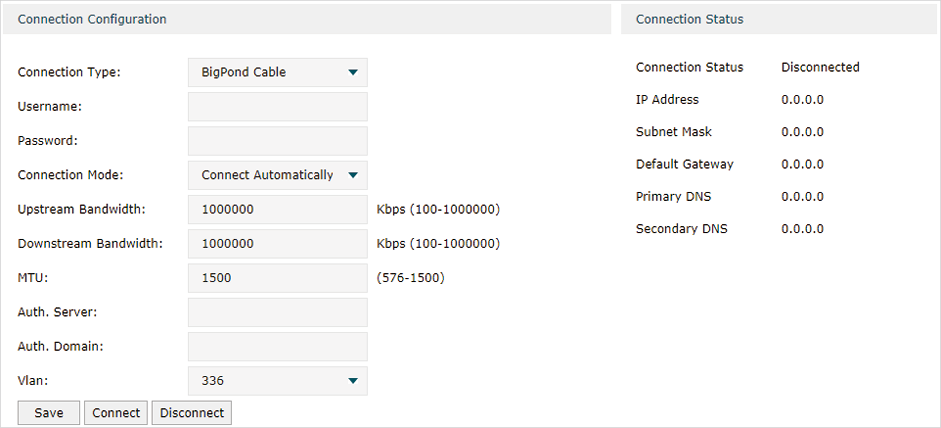
In Connection Configuration section, select the connection type as BigPond Cable. Enter the corresponding parameters and click Save.
|
Connection Type |
Choose the connection type as BigPond if your ISP provides you with a BigPond account. |
|
Username |
Enter the BigPond username provided by your ISP. |
|
Password |
Enter the BigPond password provided by your ISP. |
|
Connection Mode |
Choose the connection mode, including Connect Automatically, Connect Manually and Time-Based. Connect Automatically: The router will activate the connection automatically when the router reboots or the connection is down. Connect Manually: You can manually activate or terminate the connection. Time-Based: During the specified period, the router will automatically activate the connection. |
|
Time |
Choose the effective time range when the Connection Mode is chosen as Time-Based. To create the time range, go to Preferences > Time Range > Time Range. |
|
Upstream Bandwidth |
Specify the upstream bandwidth of the WAN port. The value configured here is the upper limit of the “Maximum Upstream Bandwidth” on Transmission > Bandwidth Control > Bandwidth Control page, to make “Bandwidth Control” take effect, please ensure this parameter is set correctly. |
|
Downstream Bandwidth |
Specify the downstream bandwidth of the WAN port. The value configured here is the lower limit of the “Maximum Downstream Bandwidth” on Transmission > Bandwidth Control > Bandwidth Control page, to make “Bandwidth Control” take effect, please ensure this parameter is set correctly. |
|
MTU |
Specify the MTU (Maximum Transmission Unit) of the WAN port. MTU is the maximum data unit transmitted in the physical network. When BigPond Cable is selected, MTU can be set in the range of 576-1500 bytes. The default value is 1500. |
|
Auth.Server |
Enter the authenticating server’s IP address or hostname. |
|
Auth.Domain |
Enter the server's domain name suffix (based on your location). For example, nsw.bigpond.net.au for NSW/ACT, vic.bigpond.net.au for VIC/TAS/WA/SA/NT, or qld.bigpond.net.au for QLD. |
|
VLAN |
Add the WAN port to a VLAN. Generally, you don’t need to manually configure it unless required by your ISP. By default, the WAN port is automatically assigned to a VLAN, and the egress rule of the VLAN is UNTAG, so the packets are transmitted by the WAN port without VLAN tags. If you want the WAN port to transmit packets with VLAN tag, you need to create the corresponding VLAN first and configure its egress rule as TAG, then manually add the WAN port to that VLAN. To create VLANs, go to Network > VLAN > VLAN. Note: When using the IPTV function, either in Bridge mode or Custom mode, the router will automatically create corresponding VLANs after you finished the configuration, and add port 1 (WAN 1) to the VLANs. Users cannot then manually select the VLAN that WAN 1 belongs to. |
|
Connect/Disconnect |
Click the button to active/terminate the connection. |
The LAN port is used to connect to the LAN clients, and works as the default gateway for these clients. You can configure the DHCP server for the LAN clients, and clients will automatically be assigned to IP addresses if the method of obtaining IP addresses is set as “Obtain IP address automatically”.
For LAN configuration, you can:
Configure the IP address of the LAN port.
Configure the DHCP server.
3.1Configuring the IP Address of the LAN Port
Choose the menu Network > LAN > LAN to load the following page.
Figure 3-1 Configuring the LAN IP Address
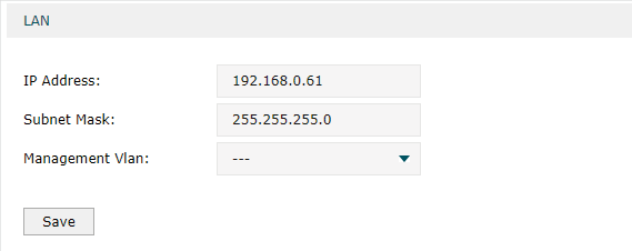
Enter the IP address of the LAN port, and click Save.
|
IP Address |
Enter the IP address of the LAN port. This IP address is the default gateway of the LAN clients, and the IP addresses of all the LAN clients should be in the same subnet with this LAN IP address. |
|
Subnet Mask |
Enter the subnet mask of the LAN port. |
|
Management Vlan |
Specify the management VLAN. If you set a management VLAN here, then only the clients in the specified VLAN can access and manage the router. The default value is “---“, which means no VLAN is selected, and any client in the LAN can access and manage the router. |
|
|
Note: •Changing the IP address of LAN port will automatically redirect the browser to the new management page. If the redirecting failed, please try to reconnect your PC to the router to automatically get a new IP address, or configure a proper static IP address manually. •Changing the IP address of the LAN port may affect some related functions, like the IP pool of the DHCP server. |
3.2Configuring the DHCP Server
You can configure an IP address pool for the DHCP server to assign IP addresses. When clients send requests to the DHCP server, the server will automatically assign IP addresses and the corresponding parameters to the clients. Moreover, if you want to reserve an IP address for a certain client, you can use Address Reservation to bind the IP address with the client’s MAC address, and the bound IP address will always be assigned to that client.
Configuring the DHCP Server
Choose the menu Network > LAN > DHCP Server to load the following page.
Figure 3-2 Configuring the DHCP Server
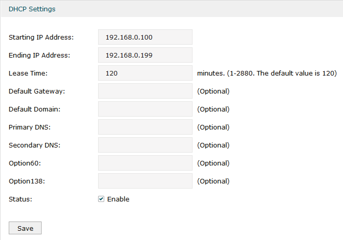
Configure the parameters of the DHCP server, then click Save.
|
Starting IP Address |
Enter the starting IP address of the DHCP server’s IP pool. The IP pool defines the IP range that can be assigned to the clients in the LAN. Note: The starting IP address should be in the same subnet with the IP address of the LAN port. |
|
Ending IP Address |
Enter the ending IP address of the DHCP server’s IP pool. The ending IP address should be greater than the starting IP address. Note: The ending IP address should be in the same subnet with the IP address of the LAN port. |
|
Lease Time |
Specify the lease time for DHCP clients. Lease time defines how long the clients can use the IP address assigned by the DHCP server. Generally, the client will automatically request the DHCP server for extending the lease time before the lease expired. If the request failed, the client will have to stop using that IP address when the lease finally expired, and try to get a new IP address from the other DHCP servers. |
|
Default Gateway |
Optional. It is recommended to enter the IP address of the LAN port. |
|
Default Domain |
Optional. Enter the domain name of your network. |
|
Primary/Secondary DNS |
Optional. Enter the DNS server address provided by your ISP. If you are not clear, please consult your ISP. |
|
Option60 |
Optional. Specify the option 60 for device identification. Mostly it is used under the scenario where the clients apply for different IP addresses from different servers according to the needs. By default, it is TP-LINK. If a client requests option 60, the server will respond a packet containing the option 60 configured here. And then the client will compare the received option 60 with its own. If they are the same, the client will accept the IP address assigned by the server, otherwise the assigned IP address will not be accepted. |
|
Option 138 |
Optional. Specify the option 138, which can be configured as the management IP address of an AC (Access Controller) device. If the APs in the local network request this option, the server will respond a packet containing this option to inform the APs of the AC’s IP address. |
|
Status |
Check the box to enable the DHCP server. |
Configuring the Address Reservation
Choose the menu Network > LAN > Address Reservation and click Add to load the following page.
Figure 3-3 Configuring the Address Reservation
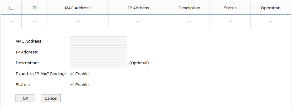
Enter the MAC address of the client and the IP address to be reserved, then click OK.
|
MAC Address |
Enter the MAC address of the client. |
|
IP Address |
Enter the IP address to be reserved. |
|
Description |
Optional. Enter a brief description for the entry. Up to 32 characters can be entered. |
|
Export to IP-MAC Binding |
Optional. Check the box to export this binding entry to IP-MAC Binding List on Firewall > Anti ARP Spoofing > IP-MAC Binding page. |
|
Status |
Check the box to enable this entry. |
3.3Viewing the DHCP Client List
Choose the menu Network > LAN > DHCP Client List to load the following page.
Figure 3-4 Viewing the DHCP Client List
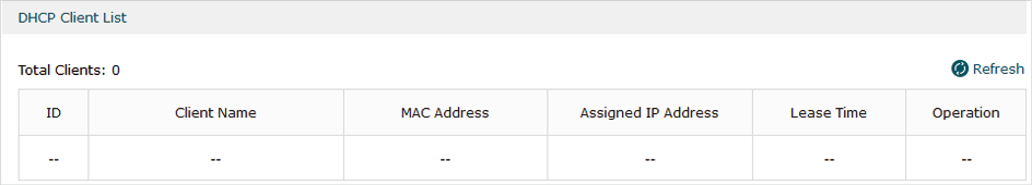
Here you can view the DHCP client list.
|
Client Name |
Displays the name of the client. |
|
MAC Address |
Displays the MAC address of the client. |
|
Assigned IP Address |
Displays the IP address assigned to the client. |
|
Lease Time |
Displays the remaining lease time of the assigned IP address. After the lease expires, the IP address will be re-assigned. |
You can configure IPTV according to the type of IPTV service provided by your ISP:
Configure IPTV based on IGMP.
Configure IPTV in Bridge mode.
Configure IPTV in Custom mode.
4.1Configuring IPTV Based on IGMP
Some ISPs provide IPTV service based on IGMP technology. In this scenario, you can just enable IGMP snooping and IGMP proxy, and connect your STB (Set-Top Box) to any LAN port of the router. The IPTV stream will then be transmitted to the corresponding LAN port.
Choose the menu Network > IPTV> IPTV to load the following page.
Figure 4-1 Configuring IPTV Based on IGMP
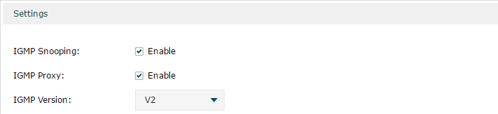
Enable IGMP Snooping and IGMP Proxy, and choose the IGMP version, then click Save.
|
IGMP Snooping |
Check the box to enable IGMP Snooping. Without IGMP Snooping, the router will broadcast multicast stream to all LAN ports, even though some LAN ports are not connected to any multicast member. With IGMP Snooping enabled, the LAN ports listen IGMP packets transmitted between the router and the clients and build a multicast table. The multicast table records the multicast members and the corresponding connected LAN port. So the multicast stream will be transmitted to only the ports that connected to multicast members. |
|
IGMP Proxy |
Check the box to enable IGMP Proxy. IGMP Proxy sends IGMP querier packets to the LAN ports to detect if there is any multicast member connected to the LAN ports. |
|
IGMP Version |
Choose the IGMP version as V2 or V3. The default is IGMP V2. |
4.2Configuring IPTV in Bridge Mode
If your ISP doesn’t provide any parameters and the IPTV service is not based on IGMP technology, you can enable IPTV function and choose the Bridge mode, then specify a port to connect IPTV set-top box.
Choose the menu Network > IPTV> IPTV to load the following page.
Figure 4-2 Configuring the Bridge Mode
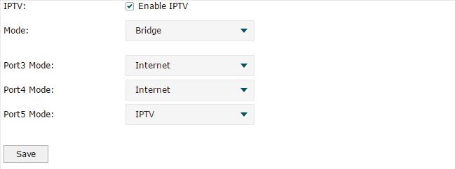
Enable IPTV function, choose the mode as Bridge, and choose a LAN port to connect to the IPTV set-top box, then click Save.
|
IPTV |
Check the box to enable IPTV function. |
|
Mode |
Choose the mode as Bridge. In Bridge mode, the LAN port chosen to connect to the IPTV becomes a dedicated port for IPTV service. |
|
Port Mode |
Specify the service to be supported by the LAN port. Internet: Specify the port to support only internet service. If you want to access the internet, you should connect your host to this port. IPTV: Specify the port to only support IPTV service. If you want to use IPTV, you should connnect your IPTV set-top box to this port. |
4.3Configuring IPTV in Custom Mode
If your ISP supports Triple-Play service, i.e., providing internet, VoIP and IPTV services over one single broadband connection, you can configure IPTV in Custom mode.
In Triple-Play, services are labeled with different VLAN tags specified by the ISP. When the WAN port receives packets, it will forward the packets to the corresponding LAN port according to the VLAN tag.
Choose the menu Network > IPTV> IPTV to load the following page.
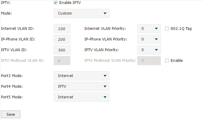
Figure 4-3 Configuring the Custom Mode
Follow these steps to configure IPTV in Custom mode:
1)Enable IPTV function and choose the mode as Custom.
|
IPTV |
Check the box to enable IPTV function. |
|
Mode |
Choose the mode as Custom. In Custom mode, the services are labeled with different VLAN tags, which is specified by the ISP. The WAN port will forward the packets to its corresponding LAN port. |
2)Enter the parameters provided by your ISP, including the VLAN IDs and priorities of different services.
|
Internet VLAN ID |
Enter the VLAN ID of the internet service. It is provided by your ISP. |
|
Internet VLAN Priority |
Enter the VLAN priority of the internet service. It is provided by your ISP. |
|
802.1Q Tag |
Optional. Check the box and the egress internet packets of WAN 1 port will be tagged. |
|
IP-Phone VLAN ID |
Enter the VLAN ID of the IP-Phone service. It is provided by your ISP. |
|
IP-Phone VLAN Priority |
Enter the VLAN priority of the IP-Phone service. It is provided by your ISP. |
|
IPTV VLAN ID |
Enter the VLAN ID of the IPTV service. It is provided by your ISP. |
|
IPTV VLAN Priority |
Enter the VLAN priority of the IPTV service. It is provided by your ISP. |
|
IPTV Multicast VLAN ID |
Enter the VLAN ID of the IPTV multicast service. It is provided by your ISP. |
|
IPTV Multicast VLAN Priority |
Enter the VLAN priority of the IPTV multicast service. It is provided by your ISP. |
3)Specify the service to support for the LAN port.
|
Port Mode |
Specify the service to be supported by the LAN port. Internet: Specify the port to support only Internet service. If you want to surf the internet, you should connect your host to this port. IP-Phone: Specify the port to support only IP-Phone service. If you want to make an IP-Phone call, you should connect your IP-Phone to this port. IPTV: Specify the port to only support IPTV service. If you want to use IPTV, you should connnect your IPTV set-top box to this port. |
|
|
Note: •Among the WAN ports, only WAN 1 supports IPTV service. So if you want to use IPTV function, connect your ISP network to WAN 1. •In Bridge mode, after you have saved the configuration, the router will automatically and randomly create some VLANs for WAN 1 and the LAN ports. These VLANs will be displayed on the VLAN page. •In Custom mode, after you configured the VLAN IDs of different services, these VLANs will automatically be created, and port 1 (WAN 1) will automatically be added to the IPTV VLAN and Internet VLAN. These VLANs will be displayed on the VLAN page. |
Generally, the MAC address does not need to be changed. However, in some particular situations, you may need to change the MAC address of the WAN port or LAN port.
Configure the MAC Address of the WAN port
In the condition that your ISP has bound the account to the MAC address of the dial-up device, if you want to replace the dial-up device with this router, you can just set the MAC address of this router’s WAN port as the same as that of the previous dial-up device for a normal internet connection.
Configure the MAC Address of the LAN port
In a complex network with all the devices are ARP bound , if you want to replace the current router with this router, you can just set the MAC address of this router’s LAN port as the same as that of the previous router, which can avoid all the devices under this network node to update their ARP binding tables.
5.1Configuring MAC Address
Choose the menu Network > MAC > MAC to load the following page.
Figure 5-1 Configuring MAC Address
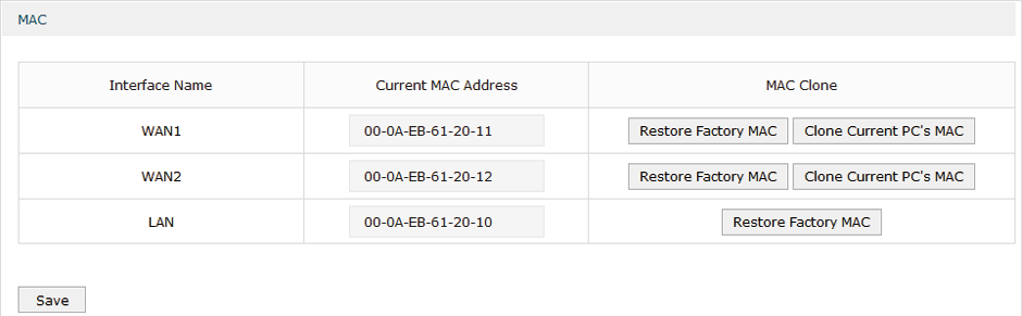
Configure the MAC address of the WAN port or LAN port according to your need, then click Save.
|
Interface Name |
Displays the WAN port and LAN port. |
|
Current MAC Address |
Configure the MAC address of the WAN port or LAN port. |
|
MAC Clone |
Restore Factory MAC: Click this button to restore the MAC address to the factory default value. Clone Current PC’s MAC: Click this button to clone the MAC address of the PC you are currently using to configure the router. It’s only available for the WAN ports. |
|
|
Note: To avoid a MAC address conflict in the LAN, it is not permitted to set the MAC address of the router’s LAN port as the MAC address of the current management PC. |
The router provides some basic switch port management function, including Statistics, Port Mirror, Port Config and Port Status.
6.1Viewing the Statistics
Choose the menu Network > Switch > Statistics to load the following page.
Figure 6-1 Viewing the Statistics
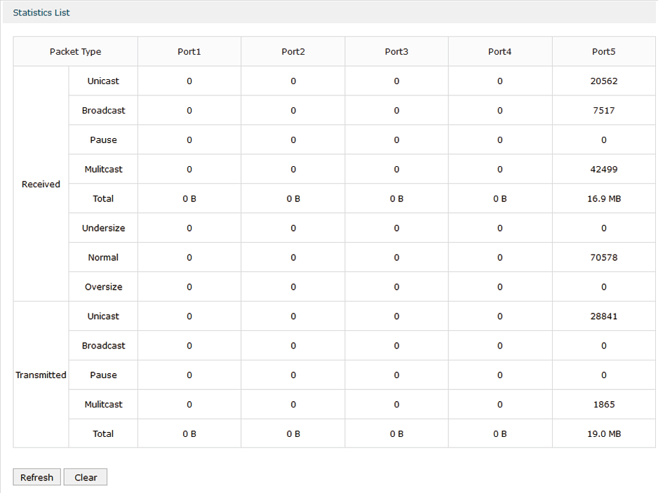
Statistics displays the detailed traffic information of each port, which allows you to monitor the traffic and locate faults promptly.
|
Unicast |
Displays the number of normal unicast packets received or transmitted on the port. |
|
Broadcast |
Displays the number of normal broadcast packets received or transmitted on the port. |
|
Pause |
Displays the number of flow control frames received or transmitted on the port. |
|
Multicast |
Displays the number of normal multicast packets received or transmitted on the port. |
|
Total |
Displays the total bytes of the received or transmitted packets (including error frames). |
|
Undersize |
Displays the number of received packets which have a length less than 64 bytes (including error frames). |
|
Normal |
Displays the number of received packets which have length between 64 bytes and the maximum frame length (including error frames). |
|
Oversize |
Displays the number of received packets that have a length greater than the maximum frame length (including error frames). |
|
|
Note: Error Frame: The frames that have a false checksum. Maximum frame length: The maximum frame length supported by the router. For untagged frames, it’s 1518 bytes long; for tagged packets, it’s 1522 bytes long. |
6.2Configuring Port Mirror
Port Mirror function allows the switch to forward packet copies of the monitored port(s) to a specific monitoring port. Then you can analyze the copied packets to monitor network traffic and troubleshoot network problems.
Choose the menu Network > Switch > Mirror to load the following page.
Figure 6-2 Configuring Port Mirror
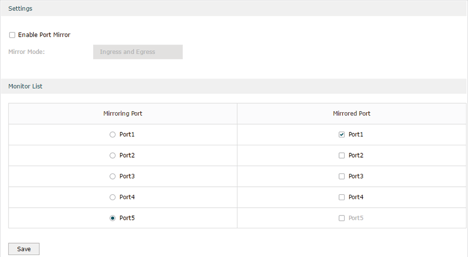
Follow these steps to configure Port Mirror:
1)In Settings section, enable Port Mirror function, and choose the mirror mode.
|
Enable Port Mirror |
Check the box to enable Port Mirror function. |
|
Mirror Mode |
Choose the mirror mode which includes Ingress, Egress and Ingress and Egress. Ingress: The packets received by the mirrored port will be copied to the mirroring port. Egress: The packets sent by the mirrored port will be copied to the mirroring port. Ingress and Egress: Both the incoming and outgoing packets through the mirrored port will be copied to the mirroring port. |
2)In the Monitor List section, set the mirroring port and the mirrored port(s), then click Save.
|
Mirroring Port |
The packets through the mirrored port will be copied to this port. Usually, the mirroring port is connected to a data diagnose device, which is used to analyze the mirrored packets for monitoring and troubleshooting the network. |
|
Mirrored Port |
The packets through this port will be copied to the mirroring port. Usually, the mirrored ports are the ports to be monitored. |
6.3Configuring Rate Control
Rate Control enables you to control the traffic rate for the specific packets on each port to manage your network.
Choose the menu Network > Switch > Rate Control to load the following page.
Figure 6-3 Configuring Rate Control
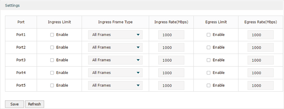
Choose the port and configure the ingress frames or egress frames limitation, then click Save.
|
Ingress Limit |
Check the box to enable the Ingress Limit feature. |
|
Ingress Frame Type |
Specify the ingress frame type to be limited. It is All Frames by default. All Frames: The ingress rate of all frames is limited. Broadcast: The ingress rate of broadcast frames is limited. Broadcast and Multicast: The ingress rate of broadcast and multicast frames is limited. |
|
Ingress Rate (Mbps) |
Specify the limit rate for the ingress packets. |
|
Egress Limit |
Check the box to enable Egress Limit feature. |
|
Egress Rate (Mbps) |
Specify the limit rate for the egress packets. |
6.4Configuring Port Config
You can configure the flow control and negotiation mode for the port.
Choose the menu Network > Switch > Port Config to load the following page.
Figure 6-4 Configuring Flow Control and Negotiation
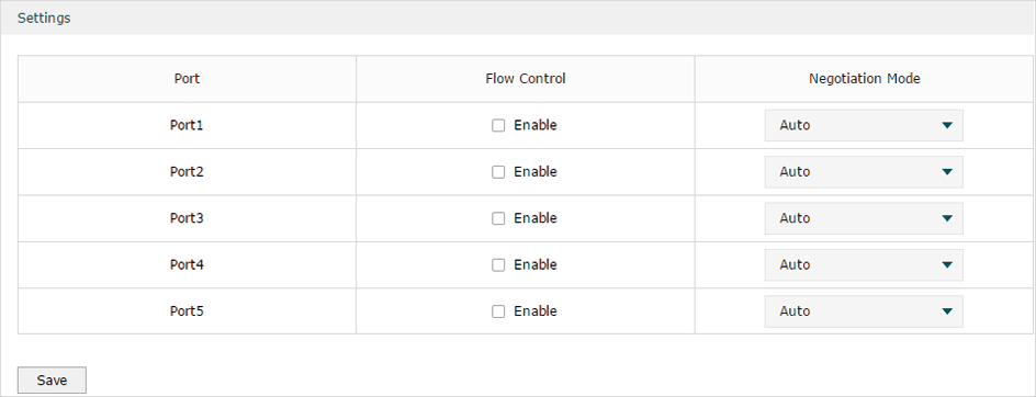
Configure the flow control and negotiation mode for a port.
|
Flow Control |
Check the box to enable the flow control function. Flow Control is the process of managing the data transmission of the sender to avoid the receiver getting overloaded. |
|
Negotiation Mode |
Select the negotiation mode for the port. You can set the mode as Auto, or manually set the speed and duplex mode for the port. It is recommended to configure both devices of a link to work in Auto-Negotiation mode or manually configure them to work in the same speed and duplex mode. If the two devices at both sides work in Auto mode, they will advertise their speed and duplex abilities to each other, and negotiate the optimal speed and duplex mode. If the local device works in Auto mode while the peer device does not, the local device will automatically detect and match the speed with the peer device. The local device will work in half-duplex mode, no matter what duplex mode the peer device is in. |
6.5Viewing Port Status
Choose the menu Network > Switch > Port Status to load the following page.
Figure 6-5 Viewing Port Status
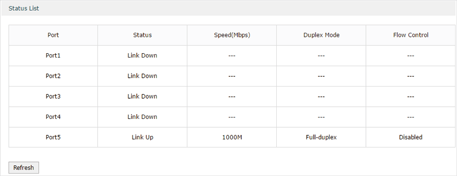
|
Status |
Displays the port status. Link Down: The port is not connected. Link Up: The port is working normally. |
|
Speed (Mbps) |
Displays the port speed. |
|
Duplex Mode |
Displays the duplex mode of the port. |
|
Flow Control |
Displays if the Flow Control is enabled. |
The router supports 802.1Q VLAN, which can divide a LAN into multiple logical LANs. Each logical LAN is a VLAN. Hosts in the same VLAN can communicate with each other. However, hosts in different VLANs cannot communicate directly. Therefore, broadcast packets can be limited to within the VLAN.
7.1Creating a VLAN
Choose the menu Network > VLAN > VLAN to load the following page.
Figure 7-1 Creating a VLAN
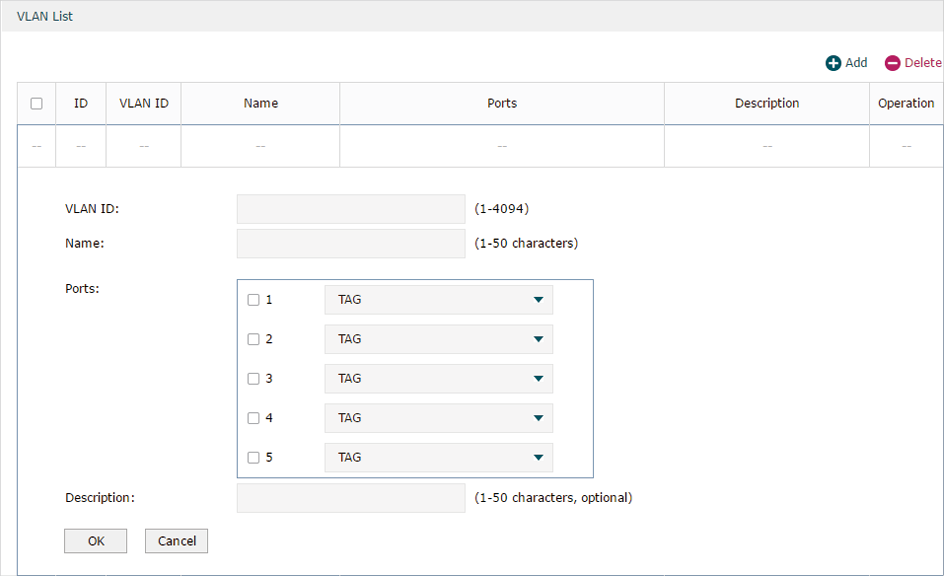
Create a VLAN and add the port(s) to the VLAN, then click OK.
|
VLAN ID |
Enter a VLAN ID. The value ranges from 1 to 4094. |
|
Name |
Specify the name of the VLAN for easy identification. |
|
Ports |
Check the box to select the port and specify the port type in the specified VLAN. The port can be divided into two types: TAG or UNTAG. TAG: The egress rule of the packets transmitted by the port is Tagged. UNTAG: The egress rule of the packets transmitted by the port is Untagged. |
|
Description |
Optional. Enter a brief description for easy management and searching. |
Viewing the VLANs
Choose the menu Network > VLAN > VLAN to load the following page.
Figure 7-2 Viewing the VLAN
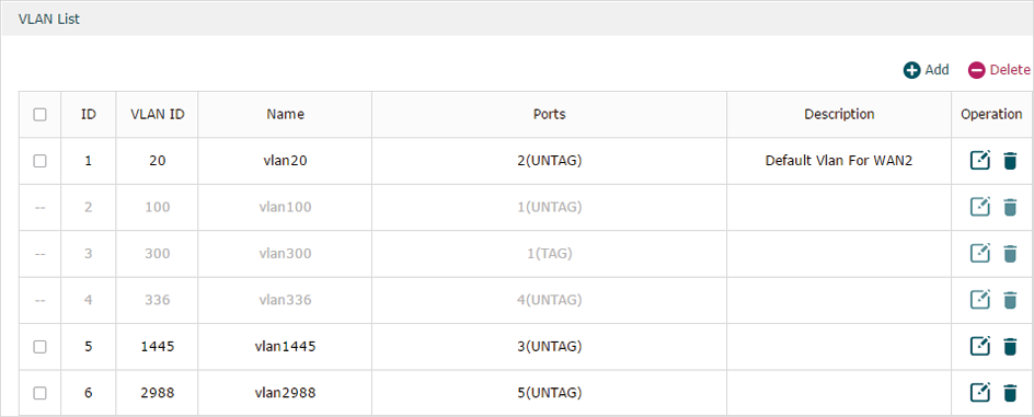
In the VLAN list you can view all the VLANs existing in the router.
|
VLAN ID |
Displays the VLAN ID. |
|
Name |
Displays the VLAN name. |
|
Ports |
Displays the ports which belongs to the corresponding VLAN. |
|
Description |
Displays the description of the VLAN. |
|
|
Note: The VLAN list contains all the VLANs existing in the router. Some of them are manually created by the user, and can be edited or deleted. Some are automatically created and referenced by the router for some special scenarios like IPTV or management VLAN, and you cannot edit or delete these VLANs. |
7.2Configuring the PVID of a Port
Choose the menu Network > VLAN > Port to load the following page.
Figure 7-3 Configuring the PVID
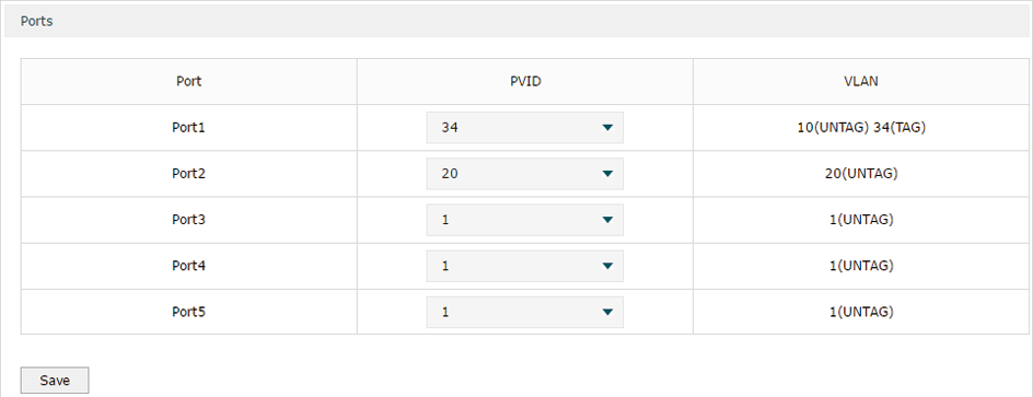
Configure the PVID of the port, then click Save.
|
Port |
Displays the port. |
|
PVID |
Specify the PVID for the port. PVID indicates the default VLAN for the corresponding port. |
|
VLAN |
Displays the VLAN(s) the port belongs to. |
To complete IPv6 configuration, follow these steps:
1)Configure the LAN to specify the type of assigning IPv6 address to the client.
2)Configure the WAN connection.
8.1Configuring the LAN
Configure the type of assigning IPv6 address to the LAN clients.
Choose the menu Network > IPv6 > LAN to load the following page.
Figure 8-1 Configuring the LAN
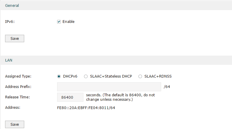
1)In Global section, enable IPv6 function and click Save.
|
IPv6 |
Check the box to enable IPv6 function for the LAN. |
2)In LAN section, configure the Assigned Type and Address prefix, then click Save.
|
Assigned Type |
Select the appropriate type of assigning the IPv6 address according to your ISP. DHCPv6: The DHCP server automatically assigns the IPv6 address and DNS information to the clients. SLAAC+Stateless DHCP: The DHCP server advertises the IPv6 prefix to the client, the client then dynamically form a host identifier that is 64 bits long and will be suffixed to the end of the advertised prefix to form an IPv6 address. Generally, the host identifier was formed using the EUI-64. The DHCP server can also offer the DNS information to the client when the client requests. SLAAC+RDNSS: The DHCP server advertises the IPv6 prefix to the client, the client then dynamically form a host identifier that is 64 bits long and will be suffixed to the end of the advertised prefix to form an IPv6 address. Generally, the host identifier was formed using the EUI-64. The DHCP server will also automatically advertise the DNS information to the client. |
|
Address Prefix |
Enter the LAN address prefix provided by your ISP. Note: If the “Prefix Delegation” in WAN configuration is enabled, the LAN prefix will be automatically assigned by the ISP, and you do not need to manually configure it here. |
|
Release Time |
The duration time in seconds when the assigned IPv6 address remains valid when you choose the Assigned Type as DHCPv6. The default value is 86400 seconds . |
|
Address |
Displays the IPv6 address of the LAN port. |
8.2Configuring the WAN
You can configure at most four WAN ports. Each WAN port can have its own IPv6 WAN connection, providing link backup and expanding the bandwidth.
To complete WAN configuration, follow these steps:
1)Configure the number of WAN ports.
2)Configure the WAN connection.
8.2.1Configuring the Number of WAN Ports
Choose the menu Network > WAN > WAN Mode to load the following page.
Figure 8-1 Configuring the WAN Mode
|
WAN Mode |
Specify the number of WAN ports. 1: Configure physical interface 1 as WAN1. 2: Configure physical interface 1 and interface 2 as WAN1 and WAN2 respectively. 3: Configure physical interface 1, interface 2 and interface3 as WAN1, WAN2 and WAN3 respectively. 4: Configure physical interface 1, interface 2, interface 3 and interface 4 as WAN1, WAN2, WAN3 and WAN4 respectively. |
|
|
Note: •When a WAN port is added, the port-related entries are automatically added; when a WAN port is deleted, the port-related entries are automatically deleted. •The router will reboot after switching the WAN mode. |
8.2.2Configuring the WAN Connection
The router supports five IPv6 connection types: Static IP, Dynamic IP (SLAAC/DHCPv6), PPPoE, 6to4 Tunnel and Pass-Through (Bridge), you can choose one according to the information provided by your ISP.
Static IP: Select this if your ISP provides you with a fixed IPv6 address, default gateway and DNS address.
Dynamic IP (SLAAC/DHCPv6): Select this if your ISP automatically assigns the IPv6 address and the corresponding parameters.
PPPoE: Select this if your ISP provides you with a PPPoE account.
6to4 Tunnel: Select this if your ISP uses 6to4 deployment for assigning address.
Pass-Through (Bridge): Select this if your ISP uses Pass-Through (Bridge) network deployment. No parameters are required for this type of connection.
Choose the menu Network > IPv6 > WAN to load the following page.
Configuring the Dynamic IP (SLAAC/DHCPv6)
Figure 8-2 Configuring the Dynamic IP (SLAAC/DHCPv6)

Follow these steps to configure Dynamic IP connection:
1)In the General section, check the box to enable IPv6 function, then click Save.
|
IPv6 |
Check the box to enable IPv6 function. |
2)In the Internet section, choose the Internet Connection type as Dynamic IP (SLAAC/DHCPv6), and configure the corresponding parameters. Then click Save.
|
Internet Connection Type |
Choose Dynamic IP (SLAAC/DHCPv6) as the connection type. |
|
IPv6 Address/Primary DNS/Secondary DNS |
Displays the IPv6 address/Primary DNS/Secondary DNS of the WAN port. These parameters are automatically assigned by the DHCPv6 server from your ISP. |
|
Renew |
Click this button to get new IPv6 parameters assigned by the DHCPv6 server from the ISP. |
|
Release |
Click this button to release the IPv6 parameters assigned by DHCPv6 server from the ISP. |
3)In the Internet section, click Advanced to configure the way of getting the IPv6 address and DNS address, and configure the Prefix Delegation. Then click Save.
|
Get IPv6 Address |
Choose the method by which the IPv6 address is obtained from the ISP. DHCPv6: The DHCP server automatically assigns the IPv6 address. SLAAC+Stateless DHCP: The DHCP server advertises the IPv6 prefix to the WAN port, the WAN port then dynamically form a host identifier that is 64 bits long and will be suffixed to the end of the advertised prefix to form an IPv6 address. Generally, the host identifier was formed using the EUI-64. |
|
Prefix Delegation |
Enable or disable prefix delegation. The prefix will be assigned to the LAN clients. Enable: The prefix of the IPv6 address will automatically be assigned by the ISP, and you do not need to configure the prefix in LAN page. Disable: You need to enter a prefix manually. Note: If more than one WAN port is enabled with Prefix Delegation, the LAN port will assign the prefix of the latest enabled WAN port to the LAN clients. |
|
DNS Address |
Choose the way of getting DNS address from the ISP. Get dynamically from ISP: The DNS address will automatically assigned by the ISP. Use the following DNS address: The user need to manually enter the DNS address provided by the ISP. |
|
Primary DNS/Secondary DNS |
Enter the DNS address provided by the ISP. |
Configuring the Static IP
Figure 8-3 Configuring the Static IP
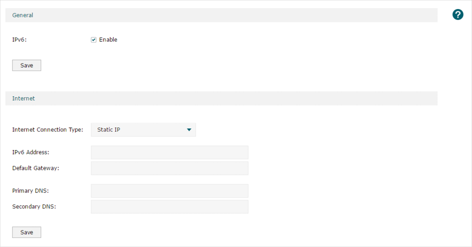
Follow these steps to configure static IP connection:
1)In the General section, check the box to enable IPv6 function, then click Save.
|
IPv6 |
Check the box to enable IPv6 function. |
2)In the Internet section, choose the Internet Connection type as Static IP, and configure the corresponding parameters. Then click Save.
|
Internet Connection Type |
Choose Static IP as the connection type. |
|
IPv6 Address |
Enter the IPv6 address provided by your ISP. |
|
Default Gateway |
Enter the default gateway provided by your ISP. |
|
Primary DNS/Secondary DNS |
Enter the DNS address provided by your ISP. |
Configuring the PPPoE
Figure 8-4 Configuring the PPPoE
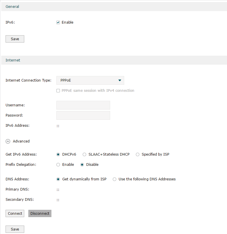
Follow these steps to configure PPPoE connection:
1)In the General section, check the box to enable IPv6 function, then click Save.
|
IPv6 |
Check the box to enable IPv6 function. |
2)In the Internet section, choose the Internet Connection type as PPPoE, and configure the corresponding parameters. Then click Save.
|
Internet Connection Type |
Choose PPPoE as the connection type. Note: If your ISP provides only one PPPoE account for both IPv4 and IPv6 connections, and you have already established an IPv4 connection on this WAN port, you can check PPPoE same session with IPv4 connection, then the WAN port will use the PPP session of IPv4 PPPoE connection to get the IPv6 address. In this case, you do not need to enter the username and password of the PPPoE account on this page. If your ISP provides two separate PPPoE accounts for the IPv4 and IPv6 connections, or the IPv4 connection of this WAN port is not based on PPPoE, please don’t check PPPoE same session with IPv4 connection and manually enter the username and password for the IPv6 connection. |
|
Username |
Enter the PPPoE username provided by your ISP. |
|
Password |
Enter the PPPoE password provided by your ISP. |
|
IPv6 Address |
Displays the IPv6 address of the WAN port. |
3)In the Internet section, click Advanced to configure the way of getting the IPv6 address and DNS address, and configure the Prefix Delegation. Then click Save.
|
Get IPv6 Address |
Choose the method by which the IPv6 address is obtained from the ISP. DHCPv6: The DHCP server automatically assigns the IPv6 address. SLAAC+Stateless DHCP: The DHCP server advertises the IPv6 prefix to the WAN port, the WAN port then dynamically forms a host identifier that is 64 bits long and will be suffixed to the end of the advertised prefix to form an IPv6 address. Generally, the host identifier is formed using the EUI-64. |
|
Prefix Delegation |
Enable or disable prefix delegation. The prefix will be assigned to the LAN clients. Enable: The prefix of the IPv6 address will automatically be assigned by the ISP, and you do not need to configure the prefix in the LAN page. Disable: You need to enter a prefix manually. Note: If more than one WAN port is enabled with Prefix Delegation, the LAN port will assign the prefix of the latest enabled WAN port to the LAN clients. |
|
DNS Address |
Choose the way of getting DNS address from the ISP. Get dynamically from ISP: The DNS address will automatically assigned by the ISP. Use the following DNS address: The user needs to manually enter the DNS address provided by the ISP. |
|
Primary DNS/Secondary DNS |
Enter the DNS address provided by the ISP. |
Configuring the 6to4 Tunnel
6to4 is an internet transition mechanism for migrating from IPv4 to IPv6, a system that allows IPv6 packets to be transmitted over an IPv4 network. The IPv6 packet will be encapsulated in the IPv4 packet and transmitted to the IPv6 destination through IPv4 network.
Figure 8-5 Configuring the 6to4 Tunnel
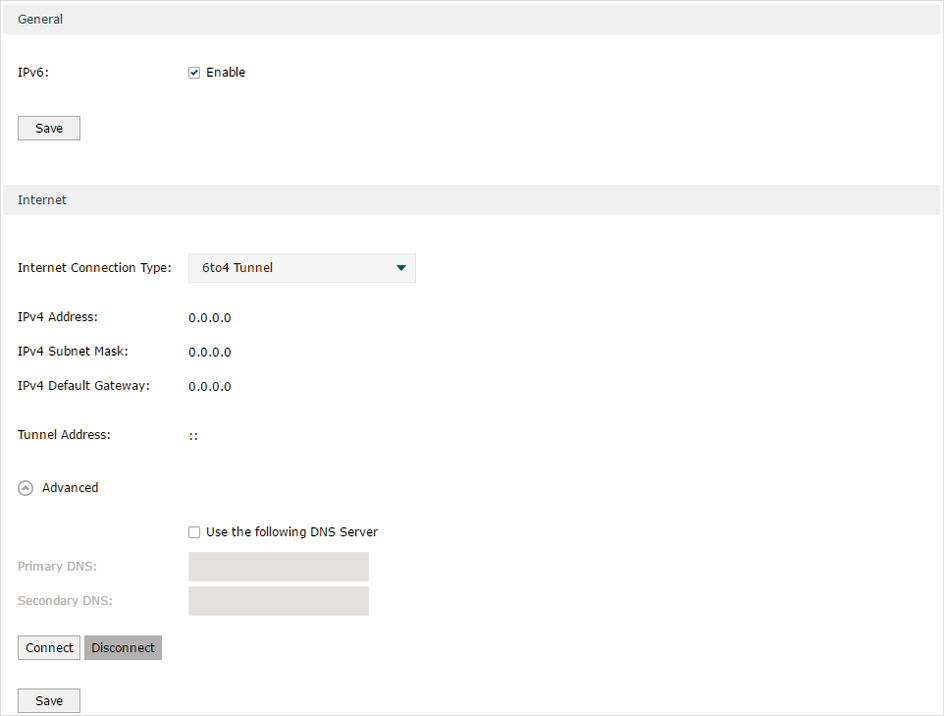
Follow these steps to configure 6to4 Tunnel connection:
1)In the General section, check the box to enable IPv6 function, then click Save.
|
IPv6 |
Check the box to enable IPv6 function. |
2)In the Internet section, choose the Internet Connection type as 6to4 Tunnel, and configure the corresponding parameters. Then click Save.
|
Internet Connection Type |
Choose the connection type as PPPoE. |
|
IPv4 Address/IPv4 Subnet Mask/IPv4 Default Gateway |
These parameters will be dynamically generated by the IPv4 information of WAN port after you click Connect. |
|
Tunnel Address |
Displays the tunnel address of the WAN port. |
3)(Optional) In Internet section, click Advanced to configure the DNS server. Then click Save.
|
Use the following DNS Server |
Check the box to manually enter the IP address DNS server provided by your ISP. Note: If this option is not enabled, the router will use the default DNS servers with the IPv6 address as 2001:4860:4860::8888 and 2001:4860:4860::8844. |
|
Primary DNS/Secondary DNS |
Enter the IPv6 address of the DNS server provided by your ISP. |
Configuring the Pass-Through (Bridge)
In Pass-Through (Bridge) mode, the router works as a transparent bridge. The IPv6 packets received from the WAN port will be transparently forwarded to the LAN port and vice versa. No extra parameter is required.
Figure 8-6 Configuring the Pass-Through (Bridge)
.png)
Follow these steps to configure Pass-Through (Bridge) connection:
1)In the General section, check the box to enable IPv6 function, then click Save.
|
IPv6 |
Check the box to enable IPv6 function. |
2)In the Internet section, choose the Internet Connection type as Pass-Through (Bridge), then click Save.
|
Internet Connection Type |
Choose the connection type as Pass-Through (Bridge). |
|
|
Note: If the Internet Connection Type of any WAN port is Pass-Through (Bridge), the IPv6 parameters of the LAN port and the other WAN ports cannot be configured. |