Configuring Layer 2 Multicast
CHAPTERS
2. IGMP Snooping Configuration
5. Multicast Filtering Configuration
6. Viewing Multicast Snooping Information
8. Appendix: Default Parameters
|
|
This guide applies to: T1500G-8T v2 or above, T1500G-10PS v2 or above, T1500G-10MPS v2 or above, T1500-28PCT v3 or above, T1600G-18TS v2 or above, T1600G-28PS v3 or above, T1600G-28TS v3 or above, T1600G-52PS v3 or above, T1600G-52TS v3 or above, T1700X-16TS v3 or above, T1700G-28TQ v3 or above, T2500G-10TS v2 or above, T2600G-18TS v2 or above, T2600G-28TS v3 or above, T2600G-28MPS v3 or above, T2600G-28SQ v1 or above, T2600G-52TS v3 or above. |

1.1Overview
In a point-to-multipoint network, packets can be sent in three ways: unicast, broadcast and multicast. With unicast, many copies of the same information will be sent to all the receivers, occupying a large bandwidth.
With broadcast, information will be sent to all users in the network no matter they need it or not, wasting network resources and impacting information security.
Multicast, however, solves all the problems caused by unicast and broadcast. With multicast, the source only need to send one piece of information, and all and only the users who need the information will receive copies of the information. In a point-to-multipoint network, multicast technology not only transmits data with high efficiency, but also saves a large bandwidth and reduces network load.
In practical applications, Internet information provider can provide value-added services such as Online Live, IPTV, Distance Education, Telemedicine, Internet Radio and Real-time Video Conferences more conveniently using multicast.
Layer 2 Multicast allows Layer 2 switches to listen for IGMP (Internet Group Management Protocol) packets between IGMP Querier and user hosts to establish multicast forwarding table and to manage and control transmission of packets.
Take IGMP Snooping as an example. When IGMP Snooping is disabled on the Layer 2 device, multicast packets will be broadcast in the Layer 2 network; when IGMP Snooping is enabled on the Layer 2 device, multicast data from a known multicast group will be transmitted to the designated receivers instead of being broadcast in the Layer 2 network.
Demonstrated as below:
Figure 1-1 IGMP Snooping
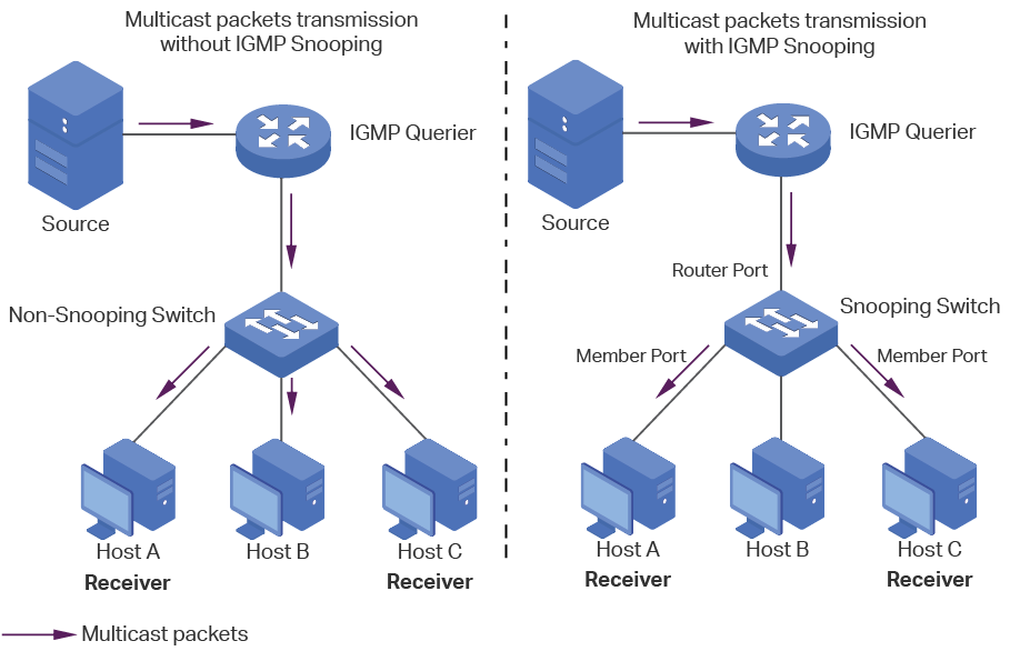
The following basic concepts of IGMP Snooping will be introduced: IGMP querier, snooping switch, router port and member port.
IGMP Querier
An IGMP querier is a multicast router (a router or a Layer 3 switch) that sends query messages to maintain a list of multicast group memberships for each attached network, and a timer for each membership.
Normally only one device acts as querier per physical network. If there are more than one multicast router in the network, a querier election process will be implemented to determine which one acts as the querier.
Snooping Switch
A snooping switch indicates a switch with IGMP Snooping enabled. The switch maintains a multicast forwarding table by snooping on the IGMP transmissions between the host and the querier. With the multicast forwarding table, the switch can forward multicast data only to the ports that are in the corresponding multicast group, so as to constrain the flooding of multicast data in the Layer 2 network.
Router Port
A router port is a port on snooping switch that is connecting to the IGMP querier.
Member Port
A member port is a port on snooping switch that is connecting to the host.
1.2Supported Features
Layer 2 Multicast protocol for IPv4: IGMP Snooping
On the Layer 2 device, IGMP Snooping transmits data on demand on data link layer by analyzing IGMP packets between the IGMP querier and the users, to build and maintain Layer 2 multicast forwarding table.
Layer 2 Multicast protocol for IPv6: MLD Snooping
On the Layer 2 device, MLD Snooping (Multicast Listener Discovery Snooping) transmits data on demand on data link layer by analyzing MLD packets between the MLD querier and the users, to build and maintain Layer 2 multicast forwarding table.
Multicast VLAN Registration (MVR)
MVR allows a single multicast VLAN to be shared for multicast member ports in different VLANs in IPv4 network. In IGMP Snooping, if member ports are in different VLANs, a copy of the multicast streams is sent to each VLAN that has member ports. While MVR provides a dedicated multicast VLAN to forward multicast traffic over the Layer 2 network, to avoid duplication of multicast streams for clients in different VLANs. Clients can dynamically join or leave the multicast VLAN without interfering with their relationships in other VLANs.
There are two types of MVR modes:
Compatible Mode
In compatible mode, the MVR switch does not forward report or leave messages from the hosts to the IGMP querier. So the IGMP querier cannot learn the multicast groups membership information from the MVR switch. You have to statically configure the IGMP querier to transmit all the required multicast streams to the MVR switch via the multicast VLAN.
Dynamic Mode
In dynamic mode, after receiving report or leave messages from the hosts, the MVR switch will forward them to the IGMP querier via the multicast VLAN (with appropriate translation of the VLAN ID). So the IGMP querier can learn the multicast groups membership information through the report and leave messages, and transmit the multicast streams to the MVR switch via the multicast VLAN according to the multicast forwarding table.
Multicast Filtering
Multicast Filtering allows you to control the set of multicast groups to which a host can belong. You can filter multicast joins on a per-port basis by configuring IP multicast profiles (IGMP profiles or MLD profiles) and associating them with individual switch ports.
To complete IGMP Snooping configuration, follow these steps:
1)Enable IGMP Snooping globally and configure the global parameters.
2)Configure IGMP Snooping for VLANs.
3)Configure IGMP Snooping for ports.
4)(Optional) Configure the advanced IGMP Snooping features:
Configure hosts to statically join a group.
Configure IGMP accounting and authentication features.
|
|
Note: IGMP Snooping takes effect only when it is enabled globally, in the corresponding VLAN and port at the same time. |

2.1.1Configuring IGMP Snooping Globally
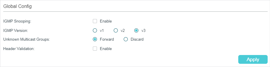
Choose the menu L2 FEATURES > Multicast > IGMP Snooping > Global Config to load the following page.
Figure 2-1 Configure IGMP Snooping Globally
Follow these steps to configure IGMP Snooping globally:
1)In the Global Config section, enable IGMP Snooping globally and configure the global parameters.
|
IGMP Snooping |
Enable or disable IGMP Snooping globally. |
|
IGMP Version |
Specify the IGMP version. v1: The switch works as an IGMPv1 Snooping switch. It can only process IGMPv1 messages from the host. Messages of other versions are ignored. v2: The switch works as an IGMPv2 Snooping switch. It can process both IGMPv1 and IGMPv2 messages from the host. IGMPv3 messages are ignored. v3: The switch works as an IGMPv3 Snooping switch. It can process IGMPv1, IGMPv2 and IGMPv3 messages from the host. |
|
Unknown Multicast Groups |
Set the way in which the switch processes data that are sent to unknown multicast groups as Forward or Discard. By default, it is Forward. Unknown multicast groups are multicast groups that do not match any of the groups announced in earlier IGMP membership reports, and thus cannot be found in the multicast forwarding table of the switch. Note: IGMP Snooping and MLD Snooping share the setting of Unknown Multicast Groups, so you have to enable MLD Snooping globally on the L2 FEATURES > Multicast > MLD Snooping > Global Config page at the same time. |
|
Header Validation |
Enable or disable Header Validation. By default, it is disabled. Generally, for IGMP packets, the TTL value should be 1, ToS field should be 0xC0, and Router Alert option should be 0x94040000. The fields to be validated depend on the IGMP version being used. IGMPv1 only checks the TTL field. IGMPv2 checks the TTL field and the Router Alert option. IGMPv3 checks TTL field, ToS field and Router Alert option. Packets that fail the validation process will be dropped. |
2)Click Apply.
2.1.2Configuring IGMP Snooping for VLANs
Before configuring IGMP Snooping for VLANs, set up the VLANs that the router ports and the member ports are in. For details, please refer to Configuring 802.1Q VLAN.
The switch supports configuring IGMP Snooping on a per-VLAN basis. After IGMP Snooping is enabled globally, you also need to enable IGMP Snooping and configure the corresponding parameters for the VLANs that the router ports and the member ports are in.
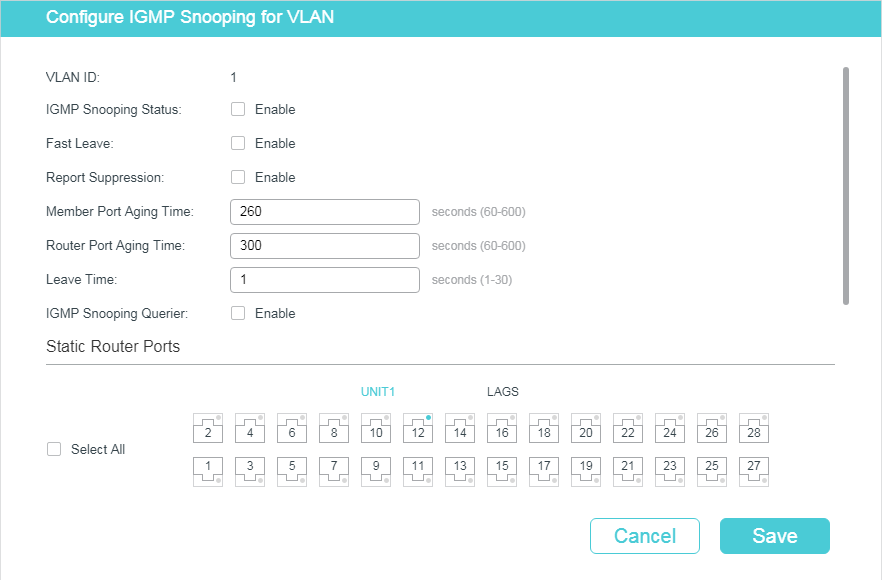
Choose the menu L2 FEATURES > Multicast > IGMP Snooping > Global Config, and click  in your desired VLAN entry in the IGMP VLAN Config section to load the following page.
Figure 2-2 Configure IGMP Snooping for VLAN
Follow these steps to configure IGMP Snooping for a specific VLAN:
1)Enable IGMP Snooping for the VLAN, and configure the corresponding parameters.
|
VLAN ID |
Displays the VLAN ID. |
|
IGMP Snooping Status |
Enable or disable IGMP Snooping for the VLAN. |
|
Fast Leave |
Enable or disable Fast Leave for the VLAN. IGMPv1 does not support Fast Leave. Without Fast Leave, after a receiver sends an IGMP leave message to leave a multicast group, the switch will forward the leave message to the Layer 3 device (the querier). From the point of view of the querier, the port connecting to the switch is a member port of the corresponding multicast group. After receiving the leave message from the switch, the querier will send out a configured number (Last Member Query Count) of group-specific queries on that port with a configured interval (Last Member Query Interval), and wait for IGMP group membership reports. If there are other receivers connecting to the switch, they will response to the queries before the Last Member Query Interval expires. If no reports are received after the response time of the last query expires, the querier will remove the port from the forwarding list of the corresponding multicast group. That is, if there are other receivers connecting to the switch, the one sent leave message have to wait until the port ages out from the switch’s forwarding list of the corresponding multicast group (the maximum waiting time is decided by the Member Port Aging Time). With Fast Leave enabled on a VLAN, the switch will remove the (Multicast Group, Port, VLAN) entry from the multicast forwarding table before forwarding the leave message to the querier. This helps to reduce bandwidth waste since the switch no longer sends the corresponding multicast streams to the VLAN of the port as soon as the port receives a leave message from the VLAN. |
|
Report Suppression |
Enable or disable Report Suppression for the VLAN. When enabled, the switch will only forward the first IGMP report message for each multicast group to the IGMP querier and suppress subsequent IGMP report messages for the same multicast group during one query interval. This feature prevents duplicate report messages from being sent to the IGMP querier. |
|
Member Port Aging Time |
Specify the aging time of the member ports in the VLAN. Once the switch receives an IGMP membership report message from a port, the switch adds this port to the member port list of the corresponding multicast group. Member ports that are learned in this way are called dynamic member ports. If the switch does not receive any IGMP membership report messages for a specific multicast group from a dynamic member port, it will no longer consider this port as a member port of this multicast group and delete it from the multicast forwarding table. |
|
Router Port Aging Time |
Specify the aging time of the router ports in the VLAN. Once the switch receives an IGMP general query message from a port, the switch adds this port to the router port list. Router ports that are learned in this way are called dynamic router ports. If the switch does not receive any IGMP general query message from a dynamic router port within the router port aging time, the switch will no longer consider this port as a router port and delete it from the router port list. |
|
Leave Time |
Specify the leave time for the VLAN. When the switch receives a leave message from a port to leave a multicast group, it will wait for a leave time before removing the port from the multicast group. During the period, if the switch receives any report messages from the port, the port will not be removed from the multicast group. Exceptions are as follows: •If the member port ages out before the Leave Time ends and no report messages are received, the port will be removed from the multicast group once its Member Port Aging Time ends. •The Leave Time mechanism will not take effect when Fast Leave takes effect. A proper leave time value can avoid other hosts connecting to the same port of the switch being mistakenly removed from the multicast group when only some of them want to leave. |
|
IGMP Snooping Querier |
Enable or disable the IGMP Snooping Querier for the VLAN. When enabled, the switch acts as an IGMP Snooping Querier for the hosts in this VLAN. A querier periodically sends a general query on the network to solicit membership information, and sends group-specific queries when it receives leave messages from hosts. Note: To enable IGMP Snooping Querier for a VLAN, IGMP Snooping should be enabled both globally and in the VLAN. |
|
Query Interval |
With IGMP Snooping Querier enabled, specify the interval between general query messages sent by the switch. |
|
Maximum Response Time |
With IGMP Snooping Querier enabled, specify the host’s maximum response time to general query messages. |
|
Last Member Query Interval |
With IGMP Snooping Querier enabled, when the switch receives an IGMP leave message, it obtains the address of the multicast group that the host wants to leave from the message. Then the switch sends out group-specific queries to this multicast group through the port receiving the leave message. This parameter determines the interval between group-specific queries. |
|
Last Member Query Count |
With IGMP Snooping Querier enabled, specify the number of group-specific queries to be sent. If specified count of group-specific queries are sent and no report message is received, the switch will delete the multicast address from the multicast forwarding table. |
|
General Query Source IP |
With IGMP Snooping Querier enabled, specify the source IP address of the general query messages sent by the switch. It should be a unicast address. |
|
Static Router Ports |
Select one or more ports to be the static router ports in the VLAN. Static router ports do not age. Multicast streams and IGMP packets to all groups in this VLAN will be forwarded through the static router ports. Multicast streams and IGMP packets to the groups that have dynamic router ports will be also forwarded through the corresponding dynamic router ports. |
|
Forbidden Router Ports |
Select ports to forbid them from being router ports in the VLAN. |
2)Click Save.
2.1.3Configuring IGMP Snooping for Ports
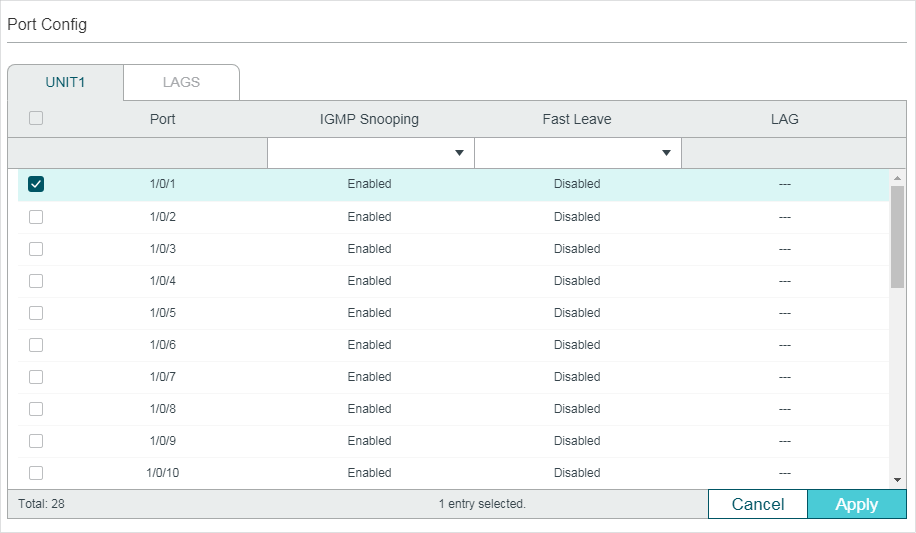
Choose the menu L2 FEATURES > Multicast > IGMP Snooping > Port Config� to load the following page.
Figure 2-3 Configure IGMP Snooping for Ports
Follow these steps to configure IGMP Snooping for ports:
1)Enable IGMP Snooping for the port and enable Fast Leave if there is only one receiver connected to the port.
|
IGMP Snooping |
Enable or disable IGMP Snooping for the port. |
|
Fast Leave |
Enable or disable Fast Leave for the port. IGMPv1 does not support fast leave. Fast Leave can be enabled on a per-port basis or per-VLAN basis. When enabled on a per-port basis, the switch will remove the port from the corresponding multicast group of all VLANs before forwarding the leave message to the querier. You should only use Fast Leave for a port when there is a single receiver connected to the port. For more details about Fast Leave, see 2.1.2 Configuring IGMP Snooping for VLANs. |
|
LAG |
Displays the LAG the port belongs to. |
2)Click Apply.
2.1.4Configuring Hosts to Statically Join a Group
Hosts or Layer 2 ports normally join multicast groups dynamically, but you can also configure hosts to statically join a group.
Choose the menu L2 FEATURES > Multicast > IGMP Snooping > Static Group Config and click  to load the following page.
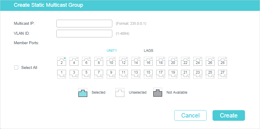
Figure 2-4 Configure Hosts to Statically Join a Group
Follow these steps to configure hosts to statically join a group:
1)Specify the multicast IP address, VLAN ID. Select the ports to be the static member ports of the multicast group.
|
Multicast IP |
Specify the address of the multicast group that the hosts need to join. |
|
VLAN ID |
Specify the VLAN that the hosts are in. |
|
Member Ports |
Select the ports that the hosts are connected to. These ports will become the static member ports of the multicast group and will never age. |
2)Click Create.
2.1.5Configuring IGMP Accounting and Authentication Features
|
|
Note: Only T2600G series switches support this feature. |
You can enable IGMP accounting and authentication according to your need. IGMP accounting is configured globally, and IGMP authentication can be enabled on a per-port basis.
To use these features, you should also set up a RADIUS server and go to SECURITY > AAA > RADIUS Config to configure RADIUS server for the switch.
Choose the menu L2 FEATURES > Multicast > IGMP Snooping > IGMP Authentication to load the following page.
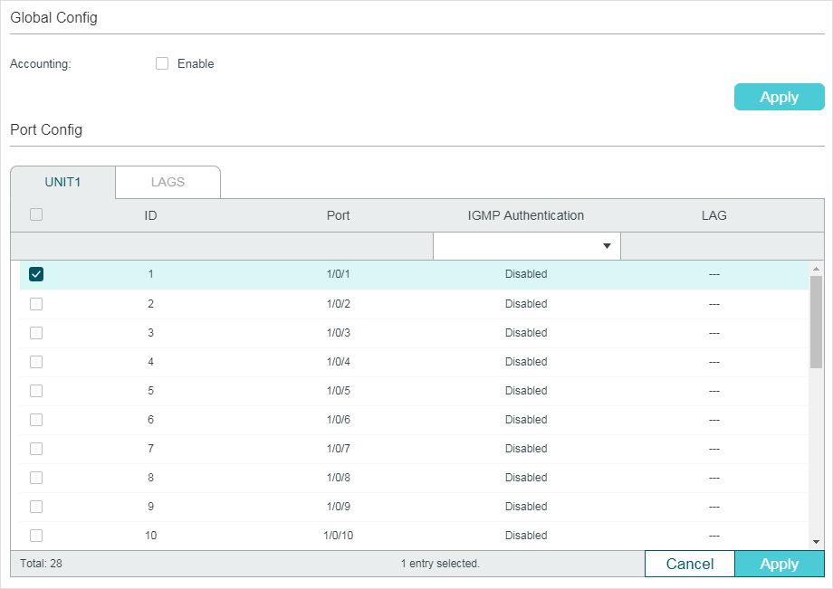
Figure 2-5 Configure IGMP Accounting and Authentication
Follow these steps to enable IGMP accounting:
1)In the Global Config section, enable IGMP Accounting globally.
|
Accounting |
Enable or disable IGMP Accounting. |
2)Click Apply.
Follow these steps to configure IGMP Authentication on ports:
1)In the Port Config section, select the ports and enable IGMP Authentication.
|
IGMP Authentication |
Enable or disable IGMP Authentication for the port. |
2)Click Apply.
2.2Using the CLI
2.2.1Configuring IGMP Snooping Globally
Follow these steps to configure IGMP Snooping globally:
|
Step 1 |
configure Enter global configuration mode. |
|
Step 2 |
ip igmp snooping Enable IGMP Snooping Globally. |
|
Step 3 |
ip igmp snooping version {v1 | v2 | v3} Configure the IGMP version. v1:The switch works as an IGMPv1 Snooping switch. It can only process IGMPv1 report messages from the host. Report messages of other versions are ignored. v2: The switch works as an IGMPv2 Snooping switch. It can process both IGMPv1 and IGMPv2 report messages from the host. IGMPv3 report messages are ignored. v3: The switch works as an IGMPv3 Snooping switch. It can process IGMPv1, IGMPv2 and IGMPv3 report messages from the host. |
|
Step 4 |
ip igmp snooping drop-unknown (Optional) Configure the way how the switch processes multicast streams that are sent to unknown multicast groups as Discard. By default, it is Forward. Unknown multicast groups are multicast groups that do not match any of the groups announced in earlier IGMP membership reports, and thus cannot be found in the multicast forwarding table of the switch. Note: IGMP Snooping and MLD Snooping share the setting of Unknown Multicast Groups, you need to ensure MLD Snooping is enabled globally. To enable MLD Snooping globally, use the ipv6 mld snooping command in global configuration mode. |
|
Step 5 |
ip igmp snooping header-validation (Optional) Enable header validation. Generally, for IGMP packets, the TTL value should be 1, ToS field should be 0xC0, and Router Alert option should be 0x94040000. The fields validated depend on the IGMP version being used. IGMPv1 only checks the TTL field. IGMPv2 checks the TTL field and the Router Alert option. IGMPv3 checks TTL field, ToS field and Router Alert option. Packets that fail the validation process will be dropped. |
|
Step 6 |
show ip igmp snooping Show the basic IGMP Snooping configuration. |
|
Step 7 |
end Return to privileged EXEC mode. |
|
Step 8 |
copy running-config startup-config Save the settings in the configuration file. |
The following example shows how to enable IGMP Snooping and header validation globally, and specify the IGMP Snooping version as IGMPv3, the way how the switch processes multicast streams that are sent to unknown multicast groups as discard.
Switch#configure
Switch(config)#ip igmp snooping
Switch(config)#ip igmp snooping version v3
Switch(config)#ipv6 mld snooping
Switch(config)#ip igmp snooping drop-unknown
Switch(config)#ip igmp snooping header-validation
Switch(config)#show ip igmp snooping
IGMP Snooping :Enable
IGMP Version :V3
Unknown Multicast :Discard
Header Validation :Enable
...
Switch(config)#end
Switch#copy running-config startup-config
2.2.2Configuring IGMP Snooping for VLANs
Before configuring IGMP Snooping for VLANs, set up the VLANs that the router ports and the member ports are in. For details, please refer to Configuring 802.1Q VLAN.
The switch supports configuring IGMP Snooping on a per-VLAN basis. After IGMP Snooping is enabled globally, you also need to enable IGMP Snooping and configure the corresponding parameters for the VLANs that the router ports and the member ports are in.
Follow these steps to configure IGMP Snooping for VLANs:
|
Step 1 |
configure Enter global configuration mode. |
|
Step 2 |
ip igmp snooping vlan-config vlan-id-list mtime member-time Enable IGMP Snooping for the specified VLANs, and specify the member port aging time for the VLANs. vlan-id-list: Specify the ID or the ID list of the VLAN(s). member-time: Specify the aging time of the member ports in the specified VLANs. Valid values are from 60 to 600 seconds. By default, it is 260 seconds. Once the switch receives an IGMP membership report message from a port, the switch adds this port to the member port list of the corresponding multicast group. Member ports that are learned in this way are called dynamic member ports. If the switch does not receive any IGMP membership report message for a specific multicast group from a dynamic member port, it will no longer consider this port as a member port of this multicast group and delete it from the multicast forwarding table. |
|
Step 3 |
ip igmp snooping vlan-config vlan-id-list rtime router-time Specify the router port aging time for the VLANs. vlan-id-list: Specify the ID or the ID list of the VLAN(s). router-time: Specify the aging time of the router ports in the specified VLANs. Valid values are from 60 to 600 seconds. By default, it is 300 seconds. Once the switch receives an IGMP general query message from a port, the switch adds this port to the router port list. Router ports that are learned in this way are called dynamic router ports. If the switch does not receive any IGMP general query message from a dynamic router port within the router port aging time, the switch will no longer consider this port as a router port and delete it from the router port list. |
|
Step 4 |
ip igmp snooping vlan-config vlan-id-list ltime leave-time Specify the router port aging time for the VLANs. vlan-id-list: Specify the ID or the ID list of the VLAN(s). leave-time: Specify the leave time for the VLAN(s). Valid values are from 1 to 30 in seconds, and the default value is 1 second. When the switch receives a leave message from a port to leave a multicast group, it will wait for a leave time before removing the port from the multicast group. During the period, if the switch receives any report messages from the port, the port will not be removed from the multicast group. Exceptions are as follows: •If the member port ages out before the Leave Time ends and no report messages are received, the port will be removed from the multicast group once its Member Port Aging Time ends. •The Leave Time mechanism will not take effect when Fast Leave takes effect. A proper leave time value can avoid other hosts connecting to the same port of the switch being mistakenly removed from the multicast group when only some of them want to leave. |
|
Step 5 |
ip igmp snooping vlan-config vlan-id-list report-suppression (Optional) Enable the Report Suppression for the VLANs. By default, it is disabled. When enabled, the switch will only forward the first IGMP report message for each multicast group to the IGMP querier and suppress subsequent IGMP report messages for the same multicast group during one query interval. This feature prevents duplicate report messages from being sent to the IGMP querier. vlan-id-list: Specify the ID or the ID list of the VLAN(s). |
|
Step 6 |
ip igmp snooping vlan-config vlan-id-list immediate-leave (Optional) Enable the Fast Leave for the VLANs. By default, it is disabled. IGMPv1 does not support fast leave. Without Fast Leave, after a receiver sends an IGMP leave message to leave a multicast group, the switch will forward the leave message to the Layer 3 device (the querier). From the point of view of the querier, the port connecting to the switch is a member port of the corresponding multicast group. After receiving the leave message from the switch, the querier will send out a configured number (Last Member Query Count) of group-specific queries on that port with a configured interval (Last Member Query Interval), and wait for IGMP group membership reports. If there are other receivers connecting to the switch, they will response to the queries before the Last Member Query Interval expires. If no reports are received after the response time of the last query expires, the querier will remove the port from the forwarding list of the corresponding multicast group. That is, if there are other receivers connecting to the switch, the one sent leave message have to wait until the port ages out from the switch’s forwarding list of the corresponding multicast group (the maximum waiting time is decided by the Member Port Aging Time). With Fast Leave enabled on a VLAN, the switch will remove the (Multicast Group, Port, VLAN) entry from the multicast forwarding table before forwarding the leave message to the querier. This helps to reduce bandwidth waste since the switch no longer sends the corresponding multicast streams to the VLAN of the port as soon as the port receives a leave message from the VLAN. vlan-id-list: Specify the ID or the ID list of the VLAN(s). |
|
Step 7 |
ip igmp snooping vlan-config vlan-id-list rport interface { fastEthernet port-list | gigabitEthernet port-list | ten-gigabitEthernet port-list| port-channel lag-list } (Optional) Specify the static router ports for the VLANs. Static router ports do not age. vlan-id-list: Specify the ID or the ID list of the VLAN(s). port-list: The number or the list of the Ethernet port that need to be configured as static router ports. lag-list: The ID or the list of the LAG that need to be configured as static router ports. |
|
Step 8 |
ip igmp snooping vlan-config vlan-id-list router-ports-forbidden interface { fastEthernet port-list | gigabitEthernet port-list | ten-gigabitEthernet port-list| port-channel lag-list } (Optional) Specify the ports to forbid them from being router ports in the VLANs. vlan-id-list: Specify the ID or the ID list of the VLAN(s). port-list: The number or the list of the Ethernet port that need to be forbidden from being router ports. lag-list: The ID or the list of the LAG that need to be forbidden from being router ports. |
|
Step 9 |
ip igmp snooping vlan-config vlan-id-list querier (Optional) Enable the IGMP Snooping Querier for the VLAN. By default, it is disabled. When enabled, the switch acts as an IGMP Snooping Querier for the hosts in this VLAN. A querier periodically sends a general query on the network to solicit membership information, and sends group-specific queries when it receives leave messages from hosts. Note: To enable IGMP Snooping Querier for a VLAN, IGMP Snooping should be enabled both globally and in the VLAN. vlan-id-list: Specify the ID or the ID list of the VLAN(s). After enabling IGMP Snooping Querier feature, you need to specify the corresponding parameters including the Last Member Query Count, Last Member Query Interval, Maximum Response Time, Query Interval and General Query Source IP. Use the command below in global configuration mode to configure the parameters: ip igmp snooping vlan-config vlan-id-list querier { max-response-time response-time | query-interval interval | general-query source-ip ip-addr | last-member-query-count num | last-member-query-interval interval } vlan-id-list: Specify the ID or the ID list of the VLAN(s). response-time: Specify the host’s maximum response time to general query messages. Valid values are from 1 to 25 seconds, and the default value is 10 seconds. query-interval interval: Specify the interval between general query messages sent by the switch. Valid values are from 10 to 300 seconds, and the default value is 60 seconds. ip-addr: Specify the source IP address of the general query messages sent by the switch. It should be a unicast address. By default, it is 0.0.0.0. num: Specify the number of group-specific queries to be sent. With IGMP Snooping Querier enabled, when the switch receives an IGMP leave message, it obtains the address of the multicast group that the host wants to leave from the message. Then the switch sends out group-specific queries to this multicast group through the port receiving the leave message. If specified count of group-specific queries are sent and no report message is received, the switch will delete the multicast address from the multicast forwarding table. Valid values are from 1 to 5, and the default value is 2. last-member-query-interval interval: Specify the interval between group-specific queries. Valid values are from 1 to 5 seconds, and the default value is 1 second. |
|
Step 10 |
show ip igmp snooping vlan vlan-id Show the basic IGMP Snooping configuration in the specified VLAN. |
|
Step 11 |
end Return to privileged EXEC mode. |
|
Step 12 |
copy running-config startup-config Save the settings in the configuration file. |
The following example shows how to enable IGMP Snooping for VLAN 1, and configure the member port aging time as 300 seconds, the router port aging time as 320 seconds, and then enable Fast Leave and Report Suppression for the VLAN:
Switch#configure
Switch(config)#ip igmp snooping vlan-config 1 mtime 300
Switch(config)#ip igmp snooping vlan-config 1 rtime 320
Switch(config)#ip igmp snooping vlan-config 1 immediate-leave
Switch(config)#ip igmp snooping vlan-config 1 report-suppression
Switch(config)#show ip igmp snooping vlan 1
Vlan Id: 1
Vlan IGMP Snooping Status: Enable
Fast Leave: Enable
Report Suppression: Enable
Router Time:320
Member Time: 300
Querier: Disable
...
Switch(config)#end
Switch#copy running-config startup-config
The following example shows how to enable IGMP Snooping querier for VLAN 1, and configure the query interval as 100 seconds, the maximum response time as 15 seconds, the last member query interval as 2 seconds, the last member query count as 3, and the general query source IP as 192.168.0.5:
Switch#configure
Switch(config)#ip igmp snooping vlan-config 1 querier
Switch(config)#ip igmp snooping vlan-config 1 querier query-interval 100
Switch(config)#ip igmp snooping vlan-config 1 querier max-response-time 15
Switch(config)#ip igmp snooping vlan-config 1 querier last-member-query-interval 2
Switch(config)#ip igmp snooping vlan-config 1 querier last-member-query-count 3
Switch(config)#ip igmp snooping vlan-config 1 querier general-query source-ip192.168.0.5
Switch(config)#show ip igmp snooping vlan 1
Vlan Id: 1
...
Querier:
Maximum Response Time: 15
Query Interval: 100
Last Member Query Interval: 2
Last Member Query Count: 3
General Query Source IP: 192.168.0.5
...
Switch(config)#end
Switch#copy running-config startup-config
2.2.3Configuring IGMP Snooping for Ports
Follow these steps to configure IGMP Snooping for ports:
|
Step 1 |
configure Enter global configuration mode. |
|
Step 2 |
interface {fastEthernet port | range fastEthernet port-list | gigabitEthernet port | range gigabitEthernet port-list | ten-gigabitEthernet port | range ten-gigabitEthernet port-list| port-channel port-channel-id | range port-channel port-channel-list} Enter interface configuration mode. |
|
Step 3 |
ip igmp snooping Enable IGMP Snooping for the port. By default, it is enabled. |
|
Step 4 |
ip igmp snooping immediate-leave (Optional) Enable Fast Leave on the specified port. Fast Leave can be enabled on a per-port basis or per-VLAN basis. When enabled on a per-port basis, the switch will remove the port from the corresponding multicast group of all VLANs before forwarding the leave message to the querier. You should only use Fast Leave for a port when there is a single receiver connected to the port. For more details about Fast Leave, see 2.2.2 Configuring IGMP Snooping for VLANs. |
|
Step 5 |
show ip igmp snooping interface [fastEthernet [ port-list ] | gigabitEthernet [ port-list ] | ten-gigabitEthernet [ port-list ] | port-channel [port-channel-list] ] basic-config Show the basic IGMP Snooping configuration on the specified port(s) or of all the ports. |
|
Step 6 |
end Return to privileged EXEC mode. |
|
Step 7 |
copy running-config startup-config Save the settings in the configuration file. |
The following example shows how to enable IGMP Snooping and fast leave for port 1/0/1-3:
Switch#configure
Switch(config)#interface range gigabitEhternet 1/0/1-3
Switch(config-if-range)#ip igmp snooping
Switch(config-if-range)#ip igmp snooping immediate-leave
Switch(config-if-range)#show ip igmp snooping interface gigabitEthernet 1/0/1-3
Port IGMP-Snooping Fast-Leave
----------- ------------------- --------------
Gi1/0/1 enable enable
Gi1/0/2 enable enable
Gi1/0/3 enable enable
Switch(config-if-range)#end
Switch#copy running-config startup-config
2.2.4Configuring Hosts to Statically Join a Group
Hosts or Layer 2 ports normally join multicast groups dynamically, but you can also configure hosts to statically join a group.
Follow these steps to configure hosts to statically join a group:
|
Step 1 |
configure Enter global configuration mode. |
|
Step 2 |
ip igmp snooping vlan-config vlan-id-list static ip interface { fastEthernet port-list | gigabitEthernet port-list | ten-gigabitEthernet port-list| port-channel lag-list } vlan-id-list: Specify the ID or the ID list of the VLAN(s). ip: Specify the IP address of the multicast group that the hosts want to join. port-list / lag-list: Specify the ports that is connected to the hosts. These ports will become static member ports of the group. |
|
Step 3 |
show ip igmp snooping groups static Show the static MLD Snooping configuration. |
|
Step 4 |
end Return to privileged EXEC mode. |
|
Step 5 |
copy running-config startup-config Save the settings in the configuration file. |
The following example shows how to configure port 1/0/1-3 in VLAN 2 to statically join the multicast group 239.1.2.3:
Switch#configure
Switch(config)#ip igmp snooping vlan-config 2 static 239.1.2.3 interface gigabitEthernet 1/0/1-3
Switch(config)#show ip igmp snooping groups static
Multicast-ip VLAN-id Addr-type Switch-port
------------ ------- --------- -----------
239.1.2.3 2 static Gi1/0/1-3
Switch(config)#end
Switch#copy running-config startup-config
2.2.5Configuring IGMP Accounting and Authentication Features
|
|
Note: Only T2600G series switches support this feature. |
You can enable IGMP accounting and authentication according to your need. IGMP accounting is configured globally, and IGMP authentication can be enabled on a per-port basis.
To use these features, you need to set up a RADIUS server and configure add the RADIUS server for the switch.
Follow these steps to add the RADIUS server and enable IGMP accounting globally:
|
Step 1 |
configure Enter global configuration mode. |
|
Step 2 |
radius-server host ip-address [ auth-port port-id ] [ acct-port port-id ] [ timeout time ] [ retransmit number ] [ nas-id nas-id ] key { [ 0 ] string | 7 encrypted-string } Add the RADIUS server and configure the related parameters as needed. host ip-address: Enter the IP address of the server running the RADIUS protocol. auth-port port-id: Specify the UDP destination port on the RADIUS server for authentication requests. The default setting is 1812. acct-port port-id: Specify the UDP destination port on the RADIUS server for accounting requests. The default setting is 1813. Usually, it is used in the 802.1X feature. timeout time: Specify the time interval that the switch waits for the server to reply before resending. The valid values are from 1 to 9 seconds and the default setting is 5 seconds. retransmit number: Specify the number of times a request is resent to the server if the server does not respond. The valid values are from 1 to 3 and the default setting is 2. nas-id nas-id: Specify the name of the NAS (Network Access Server) to be contained in RADIUS packets for identification. It ranges from 1 to 31 characters. The default value is the MAC address of the switch. Generally, the NAS indicates the switch itself. key { [ 0 ] string | 7 encrypted-string }: Specify the shared key. 0 and 7 represent the encryption type. 0 indicates that an unencrypted key will follow. 7 indicates that a symmetric encrypted key with a fixed length will follow. By default, the encryption type is 0. string is the shared key for the switch and the server, which contains 31 characters at most. encrypted-string is a symmetric encrypted key with a fixed length, which you can copy from the configuration file of another switch. The key or encrypted-key you configure here will be displayed in the encrypted form. |
|
Step 3 |
ip igmp snooping accouting Enable IGMP accounting globally. |
|
Step 4 |
show ip igmp snooping Show the basic IGMP Snooping configuration. |
|
Step 5 |
end Return to privileged EXEC mode. |
|
Step 6 |
copy running-config startup-config Save the settings in the configuration file. |
Follow these steps to enable IGMP authentication for ports:
|
Step 1 |
configure Enter global configuration mode. |
|
Step 2 |
interface {fastEthernet port | range fastEthernet port-list | gigabitEthernet port | range gigabitEthernet port-list | ten-gigabitEthernet port | range ten-gigabitEthernet port-list| port-channel port-channel-id | range port-channel port-channel-list} Enter interface configuration mode. |
|
Step 3 |
ip igmp snooping authentication Enable IGMP Snooping authentication for the port. By default, it is enabled. |
|
Step 4 |
show ip igmp snooping interface [fastEthernet [ port-list ] | gigabitEthernet [ port-list ] | ten-gigabitEthernet [ port-list ] | port-channel [port-channel-list] ] authentication Show the basic IGMP Snooping configuration on the specified port(s) or of all the ports. |
|
Step 5 |
end Return to privileged EXEC mode. |
|
Step 6 |
copy running-config startup-config Save the settings in the configuration file. |
The following example shows how to enable IGMP accounting globally:
Switch#configure
Switch(config)#ip igmp snooping accounting
Switch(config)#show ip igmp snooping
...
Global Authentication Accounting: Enable
Enable Port: Gi1/0/1-28, Po1-14
Enable VLAN:
Switch(config)#end
Switch#copy running-config startup-config
The following example shows how to enable IGMP authentication on port 1/0/1-3:
Switch#configure
Switch(config)#interface range gigabitEhternet 1/0/1-3
Switch(config-if-range)#ip igmp snooping authentication
Switch(config-if-range)#show ip igmp snooping interface gigabitEthernet 1/0/1-3 authentication
Port IGMP-Authentication
----------- -------------------------
Gi1/0/1 enable
Gi1/0/2 enable
Gi1/0/3 enable
Switch(config)#end
Switch#copy running-config startup-config
To complete MLD Snooping configuration, follow these steps:
1)Enable MLD Snooping globally and configure the global parameters.
2)Configure MLD Snooping for VLANs.
3)Configure MLD Snooping for ports.
4)(Optional) Configure hosts to statically join a group.
|
|
Note: MLD Snooping takes effect only when it is enabled globally, in the corresponding VLAN and port at the same time. |
3.1.1Configuring MLD Snooping Globally
Choose the menu L2 FEATURES > Multicast > MLD Snooping > Global Config to load the following page.
Figure 3-1 Configure MLD Snooping Globally

Follow these steps to configure MLD Snooping globally:
1)In the Global Config section, enable MLD Snooping and configure the Unknown Multicast Groups feature globally.
|
MLD Snooping |
Enable or disable MLD Snooping globally. |
|
Unknown Multicast Groups |
Configure the way in which the switch processes data that are sent to unknown multicast groups as Forward or Discard. By default, it is Forward. Unknown multicast groups are multicast groups that do not match any of the groups announced in earlier IGMP membership reports, and thus cannot be found in the multicast forwarding table of the switch. Note: IGMP Snooping and MLD Snooping share the setting of Unknown Multicast Groups, so you have to enable IGMP Snooping globally on the L2 FEATURES > Multicast > IGMP Snooping > Global Config page at the same time. |
2)Click Apply.
3.1.2Configuring MLD Snooping for VLANs
Before configuring MLD Snooping for VLANs, set up the VLANs that the router ports and the member ports are in. For details, please refer to Configuring 802.1Q VLAN.
The switch supports configuring MLD Snooping on a per-VLAN basis. After MLD Snooping is enabled globally, you also need to enable MLD Snooping and configure the corresponding parameters for the VLANs that the router ports and the member ports are in.
Choose the menu L2 FEATURES > Multicast > MLD Snooping > Global Config, and click in your desired VLAN entry in the MLD VLAN Config section to load the following page.
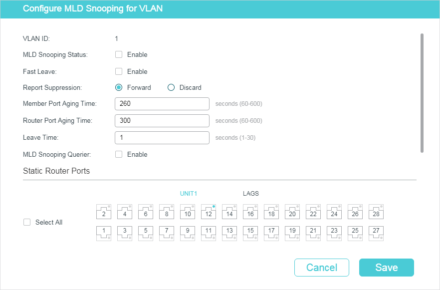
Figure 3-2 Configure MLD Snooping for VLAN
Follow these steps to configure MLD Snooping for a specific VLAN:
1)Enable MLD Snooping for the VLAN, and configure the corresponding parameters.
|
VLAN ID |
Displays the VLAN ID. |
|
MLD Snooping Status |
Enable or disable MLD Snooping for the VLAN. |
|
Fast Leave |
Enable or disable Fast Leave for the VLAN. Without Fast Leave, after a receiver sends an MLD done message (equivalent to an IGMP leave message) to leave a multicast group, the switch will forward the done message to the Layer 3 device (the querier). From the point of view of the querier, the port connecting to the switch is a member port of the corresponding multicast group. After receiving the done message from the switch, the querier will send out a configured number (Last Listener Query Count) of Multicast-Address-Specific Queries (MASQs) on that port with a configured interval (Last Listener Query Interval), and wait for MLD reports. If there are other receivers connecting to the switch, they will response to the MASQs before the Last Listener Query Interval expires. If no reports are received after the response time of the last query expires, the querier will remove the port from the forwarding list of the corresponding multicast group. That is, if there are other receivers connecting to the switch, the one sent done message have to wait until the port ages out from the switch’s forwarding list of the corresponding multicast group (the maximum waiting time is decided by the Member Port Aging Time). With Fast Leave enabled on a VLAN, the switch will remove the (Multicast Group, Port, VLAN) entry from the multicast forwarding table before forwarding the done message to the querier. This helps to reduce bandwidth waste since the switch no longer sends the corresponding multicast streams to the VLAN of the port as soon as the port receives a done message from the VLAN. |
|
Report Suppression |
Enable or disable Report Suppression for the VLAN. When enabled, the switch will only forward the first MLD report message for each multicast group to the MLD querier and suppress subsequent MLD report messages for the same multicast group during one query interval. This feature prevents duplicate report messages from being sent to the MLD querier. |
|
Member Port Aging Time |
Specify the aging time of the member ports in the VLAN. Once the switch receives an MLD report message from a port, the switch adds this port to the member port list of the corresponding multicast group. Member ports that are learned in this way are called dynamic member ports. If the switch does not receive any MLD report messages for a specific multicast group from a dynamic member port, it will no longer consider this port as a member port of this multicast group and delete it from the multicast forwarding table. |
|
Router Port Aging Time |
Specify the aging time of the router ports in the VLAN. Once the switch receives an MLD general query message from a port, the switch adds this port to the router port list. Router ports that are learned in this way are called dynamic router ports. If the switch does not receive any MLD general query messages from a dynamic router port within the router port aging time, the switch will no longer consider this port as a router port and delete it from the router port list. |
|
Leave Time |
Specify the leave time for the VLAN. When the switch receives a done message from a port to leave a multicast group, it will wait for a leave time before removing the port from the multicast group. During the period, if the switch receives any report messages from the port, the port will not be removed from the multicast group. Exceptions are as follows: •If the member port ages out before the Leave Time ends and no report messages are received, the port will be removed from the multicast group once its Member Port Aging Time ends. •The Leave Time mechanism will not take effect when Fast Leave takes effect. A proper leave time value can avoid other hosts connecting to the same port of the switch being mistakenly removed from the multicast group when only some of them want to leave. |
|
MLD Snooping Querier |
Enable or disable the MLD Snooping Querier for the VLAN. When enabled, the switch acts as an MLD Snooping Querier for the hosts in this VLAN. A querier periodically sends a general query on the network to solicit membership information, and sends MASQs when it receives done messages from hosts. Note: To enable MLD Snooping Querier for a VLAN, MLD Snooping should be enabled both globally and in the VLAN. |
|
Query Interval |
With MLD Snooping Querier enabled, specify the interval between general query messages sent by the switch. |
|
Maximum Response Time |
With MLD Snooping Querier enabled, specify the host’s maximum response time to general query messages. |
|
Last Listener Query Interval |
With MLD Snooping Querier enabled, when the switch receives a done message, it obtains the address of the multicast group that the host wants to leave from the message. Then the switch sends out MASQs to this multicast group through the port receiving the done message. This parameter determines the interval between MASQs. |
|
Last Listener Query Count |
With MLD Snooping Querier enabled, specify the number of MASQs to be sent. If specified count of MASQs are sent and no report message is received, the switch will delete the multicast address from the multicast forwarding table. |
|
General Query Source IP |
With MLD Snooping Querier enabled, specify the source IPv6 address of the general query messages sent by the switch. It should be an IPv6 link-local address.. |
|
Static Router Ports |
Select one or more ports to be the static router ports in the VLAN. Static router ports do not age. Multicast streams and MLD packets to all groups in this VLAN will be forwarded through the static router ports. Multicast streams and MLD packets to the groups that have dynamic router ports will be also forwarded through the corresponding dynamic router ports. |
|
Forbidden Router Ports |
Select the ports to forbid them from being router ports in the VLAN. |
2)Click Save.
3.1.3Configuring MLD Snooping for Ports
Choose the menu L2 FEATURES > Multicast > MLD Snooping > Port Config to load the following page.
Figure 3-3 Configure MLD Snooping for Ports

Follow these steps to configure MLD Snooping for ports:
1)Enable MLD Snooping for the port and enable Fast Leave if there is only one receiver connected to the port.
|
MLD Snooping |
Enable or disable MLD Snooping for the port. |
|
Fast Leave |
Enable or disable Fast Leave for the port. Fast Leave can be enabled on a per-port basis or per-VLAN basis. When enabled on a per-port basis, the switch will remove the port from the corresponding multicast group of all VLANs before forwarding the done message to the querier. You should only use Fast Leave for a port when there is a single receiver connected to the port. For more details about Fast Leave, see 3.1.2 Configuring MLD Snooping for VLANs. |
|
LAG |
Displays the LAG the port belongs to. |
2)Click Apply.
3.1.4Configuring Hosts to Statically Join a Group
Hosts or Layer 2 ports normally join multicast groups dynamically, but you can also configure hosts to statically join a group.
Choose the menu L2 FEATURES > Multicast > MLD Snooping > Static Group Config and click to load the following page.
Figure 3-4 Configure Hosts to Statically Join a Group
.png)
Follow these steps to configure hosts to statically join a group:
1)Specify the multicast IP address, VLAN ID. Select the ports to be the static member ports of the multicast group.
|
Multicast IP |
Specify the IPv6 address of the multicast group that the hosts need to join. |
|
VLAN ID |
Specify the VLAN that the hosts are in. |
|
Member Ports |
Select the ports that the hosts are connected to. These ports will become the static member ports of the multicast group and will never age. |
2)Click Create.
3.2Using the CLI
3.2.1Configuring MLD Snooping Globally
Follow these steps to configure MLD Snooping globally:
|
Step 1 |
configure Enter global configuration mode. |
|
Step 2 |
ipv6 mld snooping Enable MLD Snooping Globally. |
|
Step 3 |
ipv6 mld snooping drop-unknown (Optional) Configure the way how the switch processes multicast streams that are sent to unknown multicast groups as Discard. By default, it is Forward. Unknown multicast groups are multicast groups that do not match any of the groups announced in earlier IGMP membership reports, and thus cannot be found in the multicast forwarding table of the switch. Note: IGMP Snooping and MLD Snooping share the setting of Unknown Multicast Groups, you need to ensure IGMP Snooping is enabled globally. To enable IGMP Snooping globally, use the ip igmp snooping command in global configuration mode. |
|
Step 4 |
show ipv6 mld snooping Show the basic IGMP Snooping configuration. |
|
Step 5 |
end Return to privileged EXEC mode. |
|
Step 6 |
copy running-config startup-config Save the settings in the configuration file. |
The following example shows how to enable MLD Snooping globally, and the way how the switch processes multicast streams that are sent to unknown multicast groups as discard.
Switch#configure
Switch(config)#ipv6 mld snooping
Switch(config)#ip igmp snooping
Switch(config)#ipv6 mld snooping drop-unknown
Switch(config)#show ipv6 mld snooping
MLD Snooping :Enable
Unknown Multicast :Discard
...
Switch(config)#end
Switch#copy running-config startup-config
3.2.2Configuring MLD Snooping for VLANs
Before configuring MLD Snooping for VLANs, set up the VLANs that the router ports and the member ports are in. For details, please refer to Configuring 802.1Q VLAN.
The switch supports configuring MLD Snooping on a per-VLAN basis. After MLD Snooping is enabled globally, you also need to enable MLD Snooping and configure the corresponding parameters for the VLANs that the router ports and the member ports are in.
Follow these steps to configure MLD Snooping for VLANs:
|
Step 1 |
configure Enter global configuration mode. |
|
Step 2 |
ipv6 mld snooping vlan-config vlan-id-list mtime member-time Enable MLD Snooping for the specified VLANs, and specify the member port aging time for the VLANs. vlan-id-list: Specify the ID or the ID list of the VLAN(s). member-time: Specify the aging time of the member ports in the specified VLANs. Valid values are from 60 to 600 seconds. By default, it is 260 seconds. Once the switch receives an MLD report message from a port, the switch adds this port to the member port list of the corresponding multicast group. Member ports that are learned in this way are called dynamic member ports. If the switch does not receive any MLD report message for a specific multicast group from a dynamic member port, it will no longer consider this port as a member port of this multicast group and delete it from the multicast forwarding table. |
|
Step 3 |
ipv6 mld snooping vlan-config vlan-id-list rtime router-time Specify the router port aging time for the VLANs. vlan-id-list: Specify the ID or the ID list of the VLAN(s). router-time: Specify the aging time of the router ports in the specified VLANs. Valid values are from 60 to 600 seconds. By default, it is 300 seconds. Once the switch receives an MLD general query message from a port, the switch adds this port to the router port list. Router ports that are learned in this way are called dynamic router ports. If the switch does not receive any MLD general query message from a dynamic router port within the router port aging time, the switch will no longer consider this port as a router port and delete it from the router port list. |
|
Step 4 |
ipv6 mld snooping vlan-config vlan-id-list ltime leave-time Specify the router port aging time for the VLANs. vlan-id-list: Specify the ID or the ID list of the VLAN(s). leave-time: Specify the leave time for the VLAN(s). Valid values are from 1 to 30 in seconds, and the default value is 1 second. When the switch receives a leave message from a port to leave a multicast group, it will wait for a leave time before removing the port from the multicast group. During the period, if the switch receives any report messages from the port, the port will not be removed from the multicast group. Exceptions are as follows: •If the member port ages out before the Leave Time ends and no report messages are received, the port will be removed from the multicast group once its Member Port Aging Time ends. •The Leave Time mechanism will not take effect when Fast Leave takes effect. A proper leave time value can avoid other hosts connecting to the same port of the switch being mistakenly removed from the multicast group when only some of them want to leave. |
|
Step 5 |
ipv6 mld snooping vlan-config vlan-id-list report-suppression (Optional) Enable Report Suppression for the VLANs. By default, it is disabled. When enabled, the switch will only forward the first MLD report message for each multicast group to the MLD querier and suppress subsequent MLD report messages for the same multicast group during one query interval. This feature prevents duplicate report messages from being sent to the MLD querier. vlan-id-list: Specify the ID or the ID list of the VLAN(s). |
|
Step 6 |
ipv6 mld snooping vlan-config vlan-id-list immediate-leave (Optional) Enable Fast Leave for the VLANs. By default, it is disabled. Without Fast Leave, after a receiver sends an MLD done message (equivalent to an IGMP leave message) to leave a multicast group, the switch will forward the done message to the Layer 3 device (the querier). From the point of view of the querier, the port connecting to the switch is a member port of the corresponding multicast group. After receiving the done message from the switch, the querier will send out a configured number (Last Listener Query Count) of Multicast-Address-Specific Queries (MASQs) on that port with a configured interval (Last Listener Query Interval), and wait for MLD reports. If there are other receivers connecting to the switch, they will response to the MASQs before the Last Listener Query Interval expires. If no reports are received after the response time of the last query expires, the querier will remove the port from the forwarding list of the corresponding multicast group. That is, if there are other receivers connecting to the switch, the one sent done message have to wait until the port ages out from the switch’s forwarding list of the corresponding multicast group (the maximum waiting time is decided by the Member Port Aging Time). With Fast Leave enabled on a VLAN, the switch will remove the (Multicast Group, Port, VLAN) entry from the multicast forwarding table before forwarding the done message to the querier. This helps to reduce bandwidth waste since the switch no longer sends the corresponding multicast streams to the VLAN of the port as soon as the port receives a done message from the VLAN. vlan-id-list: Specify the ID or the ID list of the VLAN(s). |
|
Step 7 |
ipv6 mld snooping vlan-config vlan-id-list rport interface { fastEthernet port-list | gigabitEthernet port-list | ten-gigabitEthernet port-list| port-channel lag-list } (Optional) Specify the static router ports for the VLANs. Static router ports do not age. vlan-id-list: Specify the ID or the ID list of the VLAN(s). port-list: The number or the list of the Ethernet port that need to be configured as static router ports. lag-list: The ID or the list of the LAG that need to be configured as static router ports. |
|
Step 8 |
ipv6 mld snooping vlan-config vlan-id-list router-ports-forbidden interface { fastEthernet port-list | gigabitEthernet port-list | ten-gigabitEthernet port-list | port-channel lag-list } (Optional) Specify the ports to forbid them from being router ports in the VLANs. vlan-id-list: Specify the ID or the ID list of the VLAN(s). port-list: The number or the list of the Ethernet port that need to be forbidden from being router ports. lag-list: The ID or the list of the LAG that need to be forbidden from being router ports. |
|
Step 9 |
ipv6 mld snooping vlan-config vlan-id-list querier (Optional) Enable MLD Snooping Querier for the VLAN. By default, it is disabled. When enabled, the switch acts as an MLD Snooping Querier for the hosts in this VLAN. A querier periodically sends a general query on the network to solicit membership information, and sends group-specific queries when it receives done messages from hosts. Note: To enable MLD Snooping Querier for a VLAN, MLD Snooping should be enabled both globally and in the VLAN. vlan-id-list: Specify the ID or the ID list of the VLAN(s). After enabling MLD Snooping Querier feature, you need to specify the corresponding parameters including the Last Member Query Count, Last Member Query Interval, Maximum Response Time, Query Interval and General Query Source IP. Use the command below in global configuration mode to configure the parameters: ipv6 mld snooping vlan-config vlan-id-list querier { max-response-time response-time | query-interval interval | general-query source-ip ip-addr | last-listener-query-count num | last-listener-query-interval interval } vlan-id-list: Specify the ID or the ID list of the VLAN(s). response-time: Specify the host’s maximum response time to general query messages. query-interval interval: Specify the interval between general query messages sent by the switch. ip-addr: Specify the source IP address of the general query messages sent by the switch. It should be an IPv6 link-local address. num: Specify the number of group-specific queries to be sent. With MLD Snooping Querier enabled, when the switch receives a done message, it obtains the address of the multicast group that the host wants to leave from the message. Then the switch sends out MASQs to this multicast group through the port receiving the done message. If specified count of MASQs are sent and no report message is received, the switch will delete the multicast address from the multicast forwarding table. last-listener-query-interval interval: Specify the interval between MASQs. |
|
Step 10 |
show ipv6 mld snooping vlan vlan-id Show the basic MLD snooping configuration in the specified VLAN. |
|
Step 11 |
end Return to privileged EXEC mode. |
|
Step 12 |
copy running-config startup-config Save the settings in the configuration file. |
The following example shows how to enable MLD Snooping for VLAN 1, and configure the member port aging time as 300 seconds, the router port aging time as 320 seconds, and then enable Fast Leave and Report Suppression for the VLAN:
Switch#configure
Switch(config)#ipv6 mld snooping vlan-config 1 mtime 300
Switch(config)#ipv6 mld snooping vlan-config 1 rtime 320
Switch(config)#ipv6 mld snooping vlan-config 1 immediate-leave
Switch(config)#ipv6 mld snooping vlan-config 1 report-suppression
Switch(config)#show ipv6 mld snooping vlan 1
Vlan Id: 1
Vlan MLD Snooping Status: Enable
Fast Leave: Enable
Report Suppression: Enable
Router Time: Enable
Member Time: Enable
Querier: Disable
...
Switch(config)#end
Switch#copy running-config startup-config
The following example shows how to enable MLD Snooping querier for VLAN 1, and configure the query interval as 100 seconds, the maximum response time as 15 seconds, the last listener query interval as 2 seconds, the last listener query count as 3, and the general query source IP as FE80::1:
Switch#configure
Switch(config)#ipv6 mld snooping vlan-config 1 querier
Switch(config)#ipv6 mld snooping vlan-config 1 querier query-interval 100
Switch(config)#ipv6 mld snooping vlan-config 1 querier max-response-time 15
Switch(config)#ipv6 mld snooping vlan-config 1 querier last-listener-query-interval 2
Switch(config)#ipv6 mld snooping vlan-config 1 querier last-listener-query-count 3
Switch(config)#ipv6 mld snooping vlan-config 1 querier general-query source-ip FE80::1
Switch(config)#show ipv6 mld snooping vlan 1
Vlan Id: 1
...
Querier: Enable
Maximum Response Time: 15
Query Interval: 100
Last Member Query Interval: 2
Last Member Query Count: 3
General Query Source IP: fe80::1
...
Switch(config)#end
Switch#copy running-config startup-config
3.2.3Configuring MLD Snooping for Ports
Follow these steps to configure MLD Snooping for ports:
|
Step 1 |
configure Enter global configuration mode. |
|
Step 2 |
interface {fastEthernet port | range fastEthernet port-list | gigabitEthernet port | range gigabitEthernet port-list | ten-gigabitEthernet port | range ten-gigabitEthernet port-list| port-channel port-channel-id | range port-channel port-channel-list} Enter interface configuration mode. |
|
Step 3 |
ipv6 mld snooping Enable MLD Snooping for the port. By default, it is enabled. |
|
Step 4 |
ipv6 mld snooping immediate-leave (Optional) Enable Fast Leave on the specified port. Fast Leave can be enabled on a per-port basis or per-VLAN basis. When enabled on a per-port basis, the switch will remove the port from the corresponding multicast group of all VLANs before forwarding the done message to the querier. You should only use Fast Leave for a port when there is a single receiver connected to the port. For more details about Fast Leave, see 3.2.2 Configuring MLD Snooping for VLANs. |
|
Step 5 |
show ipv6 mld snooping interface [fastEthernet [ port-list ] | gigabitEthernet [ port-list ] | ten-gigabitEthernet [ port-list ] | port-channel [port-channel-list]] basic-config Show the basic MLD Snooping configuration on the specified port(s) or of all the ports. |
|
Step 6 |
end Return to privileged EXEC mode. |
|
Step 7 |
copy running-config startup-config Save the settings in the configuration file. |
The following example shows how to enable MLD Snooping and fast leave for port 1/0/1-3:
Switch#configure
Switch(config)#interface range gigabitEhternet 1/0/1-3
Switch(config-if-range)#ipv6 mld snooping
Switch(config-if-range)#ipv6 mld snooping immediate-leave
Switch(config-if-range)#show ipv6 mld snooping interface gigabitEthernet 1/0/1-3
Port MLD-Snooping Fast-Leave
----------- ------------------- --------------
Gi1/0/1 enable enable
Gi1/0/2 enable enable
Gi1/0/3 enable enable
Switch(config-if-range)#end
Switch#copy running-config startup-config
3.2.4Configuring Hosts to Statically Join a Group
Hosts or Layer 2 ports normally join multicast groups dynamically, but you can also configure hosts to statically join a group.
Follow these steps to configure hosts to statically join a group:
|
Step 1 |
configure Enter global configuration mode. |
|
Step 2 |
ipv6 mld snooping vlan-config vlan-id-list static ip interface {fastEthernet port-list | gigabitEthernet port-list | ten-gigabitEthernet port-list | port-channel lag-list} vlan-id-list: Specify the ID or the ID list of the VLAN(s). ip: Specify the IP address of the multicast group that the hosts want to join. port-list / lag-list: Specify the ports that is connected to the hosts. These ports will become static member ports of the group. |
|
Step 3 |
show ipv6 mld snooping groups static Show the static MLD Snooping configuration. |
|
Step 4 |
end Return to privileged EXEC mode. |
|
Step 5 |
copy running-config startup-config Save the settings in the configuration file. |
The following example shows how to configure port 1/0/1-3 in VLAN 2 to statically join the multicast group FF80::1001:
Switch#configure
Switch(config)#ipv6 mld snooping vlan-config 2 static FF80::1001 interface gigabitEthernet 1/0/1-3
Switch(config)#show ipv6 mld snooping groups static
Multicast-ip VLAN-id Addr-type Switch-port
-------------- ------- --------- -----------
ff80::1001 2 static Gi1/0/1-3
Switch(config)#end
Switch#copy running-config startup-config
To complete MVR configuration, follow these steps:
1)Configure 802.1Q VLANs.
2)Configure MVR globally.
3)Add multicast groups to MVR.
4)Configure MVR for the ports.
5)Statically add ports to MVR groups.
Configuration Guidelines
MVR does not support IGMPv3 messages.
Do not configure MVR on private VLAN ports, otherwise MVR cannot take effect.
MVR operates on the underlying mechanism of IGMP Snooping, but the two features operate independently of each other. Both protocols can be enabled on a port at the same time. When both are enabled, MVR listens to the report and leave messages only for the multicast groups configured in MVR. All other multicast groups are managed by IGMP Snooping.
4.1.1Configuring 802.1Q VLANs
Before configuring MVR, create an 802.1Q VLAN as the multicast VLAN. Add all source ports (the uplink ports that receive multicast data from the router) to the multicast VLAN as tagged ports. Configure 802.1Q VLANs for the receiver ports (ports that are connecting to the hosts) according to network requirements. Note that receiver ports can only belong to one VLAN and cannot be added to the multicast VLAN. For details, refer to Configuring 802.1Q VLAN.
4.1.2Configuring MVR Globally
Choose the menu L2 FEATURES > Multicast > MVR > MVR Config to load the following page.
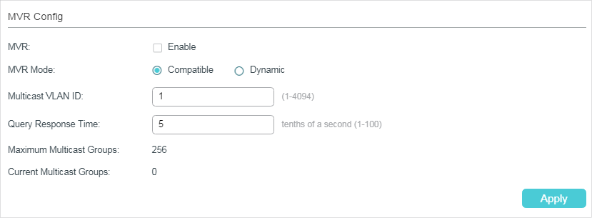
Figure 4-1 Configure MVR Globally
Follow these steps to configure MVR globally:
1)Enable MVR globally and configure the global parameters.
|
MVR |
Enable or disable MVR globally. |
|
MVR Mode |
Specify the MVR mode as compatible or dynamic. Compatible: In this mode, the switch does not forward report or leave messages from the hosts to the IGMP querier. This means IGMP querier cannot learn the multicast groups’ membership information from the switch. The IGMP querier must be statically configured to transmit all the required multicast streams to the switch via the multicast VLAN. Dynamic: In this mode, after receiving report or leave messages from the hosts, the switch will forward them to the IGMP querier via the multicast VLAN (with appropriate translation of the VLAN ID). The IGMP querier can learn the multicast groups’ membership information through the report and leave messages, and transmit the multicast streams to the switch via the multicast VLAN according to the multicast forwarding table. |
|
Multicast VLAN ID |
Specify an existing 802.1Q VLAN as the multicast VLAN. |
|
Query Response Time |
Specify the maximum time to wait for the IGMP membership report since the switch receives an IGMP leave message on a receiver port. After receiving an IGMP leave message from a receiver port, the switch will send out group-specific queries and wait for IGMP membership reports. If no IGMP membership reports are received before the Query Response Time expires, the switch will remove the port from the multicast group. |
|
Maximum Multicast Groups |
Displays the maximum number of multicast groups that can be configured on the switch. |
|
Current Multicast Groups |
Displays the current number of multicast groups that have been configured on the switch. |
2)Click Apply.
4.1.3Adding Multicast Groups to MVR
You need to manually add multicast groups to the MVR. Choose the menu L2 FEATURES > Multicast > MVR > MVR Group Config and click  to load the following page.
Figure 4-2 Add Multicast Groups to MVR
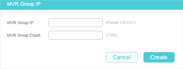
Follow these steps to add multicast groups to MVR:
1)Specify the IP address of the multicast groups.
|
MVR Group IP / MVR Group Count |
Specify the start IP address and the number of contiguous series of multicast groups. Multicast data sent to the address specified here will be sent to all source ports on the switch and all receiver ports that have requested to receive data from that multicast address. |
2)Click Create.
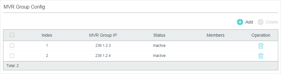
Then the added multicast groups will appear in the MVR group table, as the following figure shows:
Figure 4-3 MVR Group Table
|
MVR Group IP |
Displays the IP address of multicast group. |
|
Status |
Displays the status of the MVR group. In compatible mode, all the MVR groups are added manually, so the status is always active. In dynamic mode, there are two status: Inactive: The MVR group is added successfully, but the source port has not received any query messages from this multicast group. Active: The MVR group is added successfully and the source port has received query messages from this multicast group. |
|
Member |
Displays the member ports in this MVR group. |
4.1.4Configuring MVR for the Port
Choose the menu L2 FEATURES > Multicast > MVR > Port Config to load the following page.
Figure 4-4 Configure MVR for the Port
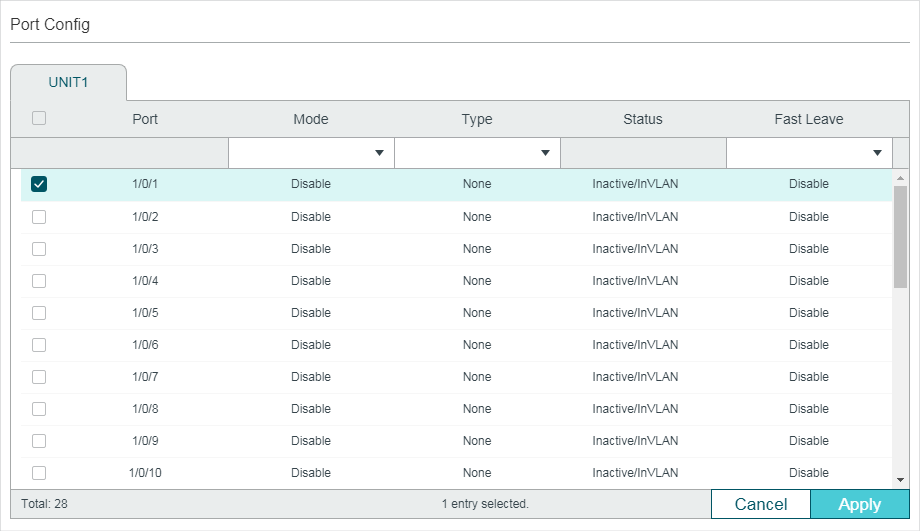
Follow these steps to add multicast groups to MVR:
1)Select one or more ports to configure.
2)Enable MVR, and configure the port type and Fast Leave feature for the port.
|
Mode |
Enable or disable MVR for the selected ports. |
|
Type |
Configure the port type. None: The port is a non-MVR port. If you attempt to configure a non-MVR port with MVR characteristics, the operation will be unsuccessful. Source: Configure the uplink ports that receive and send multicast data on the multicast VLAN as source ports. Source ports should belong to the multicast VLAN. In compatible mode, source ports will be automatically added to all multicast groups, while in dynamic mode, you need to manually add them to the corresponding multicast groups. Receiver: Configure the ports that are connecting to the hosts as receiver ports. A receiver port can only belong to one VLAN, and cannot belong to the multicast VLAN. In both modes, the switch will add or remove the receiver ports to the corresponding multicast groups by snooping the report and leave messages from the hosts. |
|
Status |
Displays the port’s status. Active/InVLAN: The port is physically up and in one or more VLANs. Active/NotInVLAN: The port is physically up and not in any VLAN. Inactive/InVLAN: The port is physically down and in one or more VLANs. Inactive/NotInVLAN: The port is physically down and not in any VLAN. |
|
Fast Leave |
Enable or disable Fast Leave for the selected ports. Only receiver ports support Fast Leave. Before enabling Fast Leave for a port, make sure there is only a single receiver device connecting to the port. |
3)Click Apply.
4.1.5(Optional) Adding Ports to MVR Groups Statically
You can add only receiver ports to MVR groups statically. The switch adds or removes receiver ports to the corresponding multicast groups by snooping the report and leave messages from the hosts. You can also statically add a receiver port to an MVR group.
Choose the menu L2 FEATURES > Multicast > MVR > Static Group Members, and click in your desired MVR group entry to load the following page.
Figure 4-5 Configure Hosts to Statically Join an MVR group
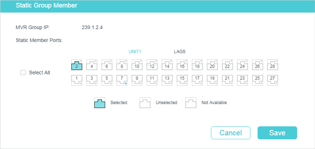
Follow these steps to statically add ports to an MVR group:
1)Select the ports to add them to the MVR group.
2)Click Save.
4.2Using the CLI
4.2.1Configuring 802.1Q VLANs
Before configuring MVR, create an 802.1Q VLAN as the multicast VLAN. Add the all source ports to the multicast VLAN as tagged ports. Configure 802.1Q VLANs for the receiver ports according to network requirements. Note that receiver ports can only belong to one VLAN and cannot be added to the multicast VLAN. For details, refer to Configuring 802.1Q VLAN.
4.2.2Configuring MVR Globally
Follow these steps to configure MVR globally:
|
Step 1 |
configure Enter global configuration mode. |
|
Step 2 |
mvr Enable MVR Globally. |
|
Step 3 |
mvr mode { compatible | dynamic } Configure the MVR mode as compatible or dynamic. compatible: In this mode, the switch does not forward report or leave messages from the hosts to the IGMP querier. So the IGMP querier cannot learn the multicast groups membership information from the switch. You have to statically configure the IGMP querier to transmit all the required multicast streams to the switch via the multicast VLAN. dynamic: In this mode, after receiving report or leave messages from the hosts, the switch will forward them to the IGMP querier via the multicast VLAN (with appropriate translation of the VLAN ID). So the IGMP querier can learn the multicast groups membership information through the report and leave messages, and transmit the multicast streams to the switch via the multicast VLAN according to the multicast forwarding table. |
|
Step 4 |
mvr vlan vlan-id Specify the multicast VLAN. vlan-id: Specify the ID of the multicast VLAN. Valid values are from 1 to 4094. |
|
Step 5 |
mvr querytime time Specify the maximum time to wait for the IGMP membership reports since the switch receives an IGMP leave message on a receiver port. time: Specify the maximum response time. After receiving an IGMP leave message from a receiver port, the switch will send out group-specific queries and wait for IGMP membership reports. If no IGMP membership reports are received before this configured time expires, the switch will remove the port from the multicast group. Valid values are from 1 to100 tenths of a second, and the default value is 5 tenths of a second. |
|
Step 6 |
mvr group ip-addr count Add multicast groups to the MVR. ip-addr: Specify the start IP address of the contiguous series of multicast groups. count: Specify the number of the multicast groups to be added to the MVR. The range is 1 to 256. |
|
Step 7 |
show mvr Show the global MVR configuration. show mvr members Show the existing MVR groups. |
|
Step 8 |
end Return to privileged EXEC mode. |
|
Step 9 |
copy running-config startup-config Save the settings in the configuration file. |
The following example shows how to enable MVR globally, and configure the MVR mode as compatible, the multicast VLAN as VLAN 2 and the query response time as 5 tenths of a second. Then add 239.1.2.3-239.1.2.5 to MVR group.
Switch#configure
Switch(config)#mvr mode compatible
Switch(config)#mvr vlan 2
Switch(config)#mvr querytime 5
Switch(config)#mvr group 239.1.2.3 3
Switch(config)#show mvr
MVR :Enable
MVR Multicast Vlan :2
MVR Max Multicast Groups :256
MVR Current Multicast Groups :3
MVR Global Query Response Time :5 (tenths of sec)
MVR Mode Type :Compatible
Switch(config)#show mvr members
MVR Group IP status Members
---------------- --------- ----------------
239.1.2.3 active
239.1.2.4 active
239.1.2.5 active
Switch(config)#end
Switch#copy running-config startup-config
4.2.3Configuring MVR for the Ports
Follow these steps to configure MVR for the ports:
|
Step 1 |
configure Enter global configuration mode. |
|
Step 2 |
interface {fastEthernet port | range fastEthernet port-list | gigabitEthernet port | range gigabitEthernet port-list | ten-gigabitEthernet port | range ten-gigabitEthernet port-list } Enter interface configuration mode. |
|
Step 3 |
mvr Enable MVR for the port. |
|
Step 4 |
mvr type { source | receiver } Configure the MVR port type as receiver or source. By default, the port is a non-MVR port. If you attempt to configure a non-MVR port with MVR characteristics, the operation fails. source: Configure the uplink ports that receive and send multicast data on the multicast VLAN as source ports. Source ports should belong to the multicast VLAN. receiver: Configure the ports that are connecting to the hosts as receiver ports. A receiver port can only belong to one VLAN, and cannot belong to the multicast VLAN. |
|
Step 5 |
mvr immediate (Optional) Enable the Fast Leave feature of MVR for the port. Only receiver ports support Fast Leave. Before enabling Fast Leave for a port, make sure there is only a single receiver device connecting to the port. |
|
Step 6 |
mvr vlan vlan-id group ip-addr (Optional) Statically add the port to an MVR group. Then the port can receive multicast traffic sent to the IP multicast address via the multicast VLAN. This command applies to only receiver ports. The switch adds or removes the receiver ports to the corresponding multicast groups by snooping the report and leave messages from the hosts. You can also statically add a receiver port to an MVR group. vlan-id: Enter the multicast VLAN ID. ip-addr: Specify the IP address of the multicast group. |
|
Step 7 |
show mvr interface {fastEthernet [port-list ] | gigabitEthernet [port-list ] | ten-gigabitEthernet [port-list ] } Show the MVR configuration of the specified interface(s). show mvr members Show the membership information of all MVR groups. |
|
Step 8 |
end Return to privileged EXEC mode. |
|
Step 9 |
copy running-config startup-config Save the settings in the configuration file. |
The following example shows how to configure port 1/0/7 as source port, and port 1/0/1-3 as receiver ports. Then statically add port 1/0/1-3 to group 239.1.2.3 and enable MVR Fast Leave for these ports. The multicast VLAN is VLAN 2.
Switch#configure
Switch(config)#interface gigabitEthernet 1/0/7
Switch(config-if)#mvr
Switch(config-if)#mvr type source
Switch(config-if)#exit
Switch(config)#interface range gigabitEthernet 1/0/1-3
Switch(config-if-range)#mvr
Switch(config-if-range)#mvr type receiver
Switch(config-if-range)#mvr immediate
Switch(config-if-range)#mvr vlan 2 group 239.1.2.3
Switch(config-if-range)#show mvr interface gigabitEtnernet 1/0/1-3,1/0/7
Port Mode Type Status Immediate Leave
----------- ---------- ------------ --------------------- ---------------------
Gi1/0/1 Enable Receiver INACTIVE/InVLAN Enable
Gi1/0/2 Enable Receiver INACTIVE/InVLAN Enable
Gi1/0/3 Enable Receiver INACTIVE/InVLAN Enable
Gi1/0/7 Enable Source INACTIVE/InVLAN Disable
Switch(config-if-range)#show mvr members
MVR Group IP status Members
---------------- --------- ----------------
239.1.2.3 active Gi1/0/1-3, 1/0/7
Switch(config)#end
Switch#copy running-config startup-config
5Multicast Filtering Configuration
To complete multicast filtering configuration, follow these steps:
1)Create the IGMP profile or MLD profile.
2)Configure multicast groups a port can join and the overflow action.
5.1Using the GUI
5.1.1Creating the Multicast Profile
You can create multicast profiles for both IPv4 and IPv6 network. With multicast profile, the switch can define a blacklist or whitelist of multicast groups so as to filter multicast sources.
The process for creating multicast profiles for IPv4 and IPv6 are similar. The following introductions take creating an IPv4 profile as an example.
Choose the menu L2 FEATURES > Multicast > Multicast Filtering > IPv4 Profile, and click  to load the following page.
|
|
Note: To create a multicast profile for IPv6, choose the menu L2 FEATURES > Multicast > Multicast Filtering > IPv6 Profile. |
Figure 5-1 Create IPv4 Profile
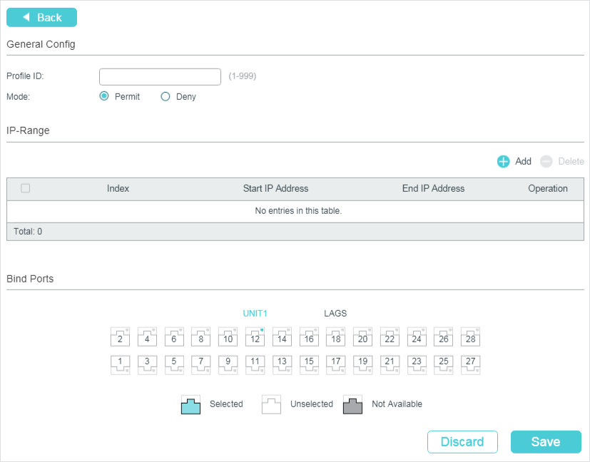
Follow these steps to create a profile.
1)In the General Config section, specify the Profile ID and Mode.
|
Profile ID |
Enter a profile ID between 1 and 999. |
|
Mode |
Select Permit or Deny as the filtering mode. Permit: Acts as a whitelist and only allows specific member ports to join specified multicast groups. Deny: Acts as a blacklist and prevents specific member ports from joining specific multicast groups. |
2)In the IP-Range section, click  to load the following page. Configure the start IP address and end IP address of the multicast groups to be filtered, and click Create.
Figure 5-2 Configure Multicast Groups to Be Filtered
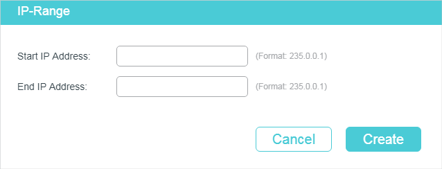
3)In the Bind Ports section, select your desired ports to be bound with the profile.
4)Click Save.
5.1.2Configure Multicast Filtering for Ports
You can modify the mapping relation between ports and profiles in batches, and configure the number of multicast groups a port can join and the overflow action.
The process for configuring multicast filtering for ports in IPv4 and IPv6 are similar. The following introductions take configuring multicast filtering for ports in IPv4 as an example.
Choose the menu L2 FEATURES > Multicast > Multicast Filtering > IPv4 Port Binding to load the following page.
|
|
Note: For IPv6, choose the menu L2 FEATURES > Multicast > Multicast Filtering > IPv6 Port Binding. |
Figure 5-3 Configure Multicast Filtering for Ports
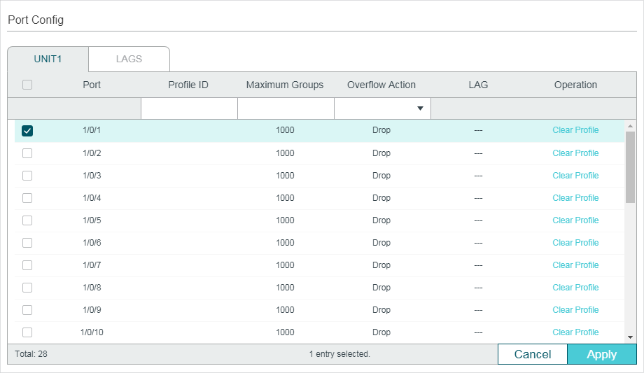
Follow these steps to bind the profile to ports and configure the corresponding parameters for the ports:
1)Select one or more ports to configure.
2)Specify the profile to be bound, and configure the maximum groups the port can join and the overflow action.
|
Profile ID |
Specify the ID of an existing profile to bind the profile to the selected ports. One port can only be bound to one profile. |
|
Maximum Groups |
Enter the number of multicast groups the port can join. For T2600G and T1600G series switches except T1600G-28TS V3, valid values are from 0 to 1000. For other switches, valid values are from 0 to 511. |
|
Overflow Action |
Select the action the switch will take with the new multicast member groups when the number of multicast groups the port has joined exceeds the maximum. Drop: Drop all subsequent membership report messages to prevent the port joining a new multicast groups. Replace: Replace the existing multicast group that has the lowest multicast MAC address with the new multicast group. |
|
LAG |
Displays the LAG the port belongs to. |
|
Operation |
Click Clear Profile to clear the binding between the profile and the port. |
3)Click Apply.
5.2Using the CLI
5.2.1Creating the Multicast Profile
You can create multicast profiles for both IPv4 and IPv6 network. With multicast profile, the switch can define a blacklist or whitelist of multicast groups so as to filter multicast sources.
Creating IGMP Profile (Multicast Profile for IPv4)
|
Step 1 |
configure Enter global configuration mode. |
|
Step 2 |
ip igmp profile id Create a new profile and enter profile configuration mode. |
|
Step 3 |
Permit Configure the profile’s filtering mode as permit. Then the profile acts as a whitelist and only allows specific member ports to join specified multicast groups. deny Configure the profile’s filtering mode as deny. Then the profile acts as a blacklist and prevents specific member ports from joining specific multicast groups. |
|
Step 4 |
range start-ip end-ip Configure the range of multicast IP addresses to be filtered. start-ip / end-ip: Specify the start IP address and end IP address of the IP range. |
|
Step 5 |
show ip igmp profile [id] Show the detailed IGMP profile configuration. |
|
Step 6 |
end Return to privileged EXEC mode. |
|
Step 7 |
copy running-config startup-config Save the settings in the configuration file. |
The following example shows how to configure Profile 1 so that the switch filters multicast streams sent to 226.0.0.5-226.0.0.10:
Switch#configure
Switch(config)#ip igmp snooping
Switch(config)#ip igmp profile 1
Switch(config-igmp-profile)#deny
Switch(config-igmp-profile)#range 226.0.0.5 226.0.0.10
Switch(config-igmp-profile)#show ip igmp profile
IGMP Profile 1
deny
range 226.0.0.5 226.0.0.10
Switch(config)#end
Switch#copy running-config startup-config
Creating MLD Profile (Multicast Profile for IPv6)
|
Step 1 |
configure Enter global configuration mode. |
|
Step 2 |
ipv6 mld profile id Create a new profile and enter profile configuration mode. |
|
Step 3 |
Permit Configure the profile’s filtering mode as permit. It is similar to a whitelist, indicating that the switch only allow specific member ports to join specific multicast groups. deny Configure the profile’s filtering mode as deny. It is similar to a blacklist, indicating that the switch disallow specific member ports to join specific multicast groups. |
|
Step 4 |
range start-ip end-ip Configure the range of multicast IP addresses to be filtered. start-ip / end-ip: Specify the start IP address and end IP address of the IP range. |
|
Step 5 |
show ipv6 mld profile [id] Show the detailed MLD profile configuration. |
|
Step 6 |
end Return to privileged EXEC mode. |
|
Step 7 |
copy running-config startup-config Save the settings in the configuration file. |
The following example shows how to configure Profile 1 so that the switch filters multicast streams sent to ff01::1234:5-ff01::1234:8:
Switch#configure
Switch(config)#ipv6 mld snooping
Switch(config)#ipv6 mld profile 1
Switch(config-mld-profile)#deny
Switch(config-mld-profile)#range ff01::1234:5 ff01::1234:8
Switch(config-mld-profile)#show ipv6 mld profile
MLD Profile 1
deny
range ff01::1234:5 ff01::1234:8
Switch(config)#end
Switch#copy running-config startup-config
5.2.2Binding the Profile to Ports
You can bind the created IGMP profile or MLD profile to ports, and configure the number of multicast groups a port can join and the overflow action.
Binding the IGMP Profile to Ports
|
Step 1 |
configure Enter global configuration mode. |
|
Step 2 |
interface {fastEthernet port | range fastEthernet port-list | gigabitEthernet port | range gigabitEthernet port-list | ten-gigabitEthernet port | range ten-gigabitEthernet port-list | port-channel port-channel-id | range port-channel port-channel-list} Enter interface configuration mode. |
|
Step 3 |
ip igmp filter profile-id Bind the IGMP profile to the specified ports. profile-id: Specify the ID of the profile to be bound. It should be an existing profile. |
|
Step 4 |
ip igmp snooping max-groups maxgroup Configure the maximum number of multicast groups the port can join. maxgroup: Specify the maximum number of multicast groups the port can join. For T2600G and T1600G series switches except T1600G-28TS V3, valid values are from 0 to 1000. For other switches, valid values are from 0 to 511. |
|
Step 5 |
ip igmp snooping max-groups action {drop | replace} Specify the action towards the new multicast group when the number of multicast groups the port joined exceeds the limit. drop: Drop all subsequent membership report messages, and the port join no more new multicast groups. replace: Replace the existing multicast group owning the lowest multicast MAC address with the new multicast group. |
|
Step 6 |
show ip igmp profile [id] Show the detailed IGMP profile configurations. show ip igmp snooping interface [fastEthernet [ port-list ] | gigabitEthernet [ port-list ] | ten-gigabitEthernet [ port-list ] | port-channel [port-channel-list ] ] max-groups Show the multicast group limitation on the specified port(s) or of all the ports. |
|
Step 7 |
end Return to privileged EXEC mode. |
|
Step 8 |
copy running-config startup-config Save the settings in the configuration file. |
The following example shows how to bind the existing Profile 1 to port 1/0/2, and specify the maximum number of multicast groups that port 1/0/2 can join as 50 and the Overflow Action as Drop:
Switch#configure
Switch(config)#interface gigabitEthernet 1/0/2
Switch(config-if)#ip igmp snooping
Switch(config-if)#ip igmp filter 1
Switch(config-if)#ip igmp snooping max-groups 50
Switch(config-if)#ip igmp snooping max-groups action drop
Switch(config-if)#show ip igmp profile
IGMP Profile 1
...
Binding Port(s)
Gi1/0/2
Switch(config-if)#show ip igmp snooping interface gigabitEthernet 1/0/2 max-groups
Port Max-Groups Overflow-Action
------------- --------------- ---------------------
Gi1/0/2 50 Drops
Switch(config)#end
Switch#copy running-config startup-config
Binding the MLD Profile to Ports
|
Step 1 |
configure Enter global configuration mode. |
|
Step 2 |
interface {fastEthernet port | range fastEthernet port-list | gigabitEthernet port | range gigabitEthernet port-list | ten-gigabitEthernet port | range ten-gigabitEthernet port-list | port-channel port-channel-id | range port-channel port-channel-list} Enter interface configuration mode. |
|
Step 3 |
ipv6 mld filter profile-id Bind the MLD profile to the specified ports. profile-id: Specify the ID of the profile to be bound. It should be an existing profile. |
|
Step 4 |
ipv6 mld snooping max-groups maxgroup Configure the maximum number of multicast groups the port can join. maxgroup: Specify the maximum number of multicast groups the port can join. The range is 0 to 1000. |
|
Step 5 |
ipv6 mld snooping max-groups action {drop | replace} Specify the action towards the new multicast group when the number of multicast groups the port joined exceeds max group. drop: Drop all subsequent membership report messages, and the port join no more new multicast groups. replace: Replace the existing multicast group owning the lowest multicast MAC address with the new multicast group. |
|
Step 6 |
show ipv6 mld profile [id] Show the detailed MLD profile configuration. show ipv6 mld snooping interface [fastEthernet [ port-list ] | gigabitEthernet [ port-list ] | ten-gigabitEthernet [ port-list ] | port-channel [port-channel-list ] ] max-groups Show the multicast group limitation on the specified port(s) or of all the ports. |
|
Step 7 |
end Return to privileged EXEC mode. |
|
Step 8 |
copy running-config startup-config Save the settings in the configuration file. |
The following example shows how to bind the existing Profile 1 to port 1/0/2, and specify the maximum number of multicast groups that port 1/0/2 can join as 50 and the Overflow Action as Drop:
Switch#configure
Switch(config)#interface gigabitEthernet 1/0/2
Switch(config-if)#ipv6 mld snooping
Switch(config-if)#ipv6 mld filter 1
Switch(config-if)#ipv6 mld snooping max-groups 50
Switch(config-if)#ipv6 mld snooping max-groups action drop
Switch(config-if)#show ipv6 mld profile
MLD Profile 1
...
Binding Port(s)
Gi1/0/2
Switch(config-if)#show ipv6 mld snooping interface gigabitEthernet 1/0/2 max-groups
Port Max-Groups Overflow-Action
------------- --------------- ---------------------
Gi1/0/2 50 Drops
Switch(config)#end
Switch#copy running-config startup-config
6Viewing Multicast Snooping Information
You can view the following multicast snooping information:
View IPv4 multicast table.
View IPv4 multicast statistics on each port.
View IPv6 multicast table.
View IPv6 multicast statistics on each port.
6.1Using the GUI
6.1.1Viewing IPv4 Multicast Table
Choose the menu L2 FEATURES > Multicast > Multicast Info > IPv4 Multicast Table to load the following page:
Figure 6-1 IPv4 Multicast Table
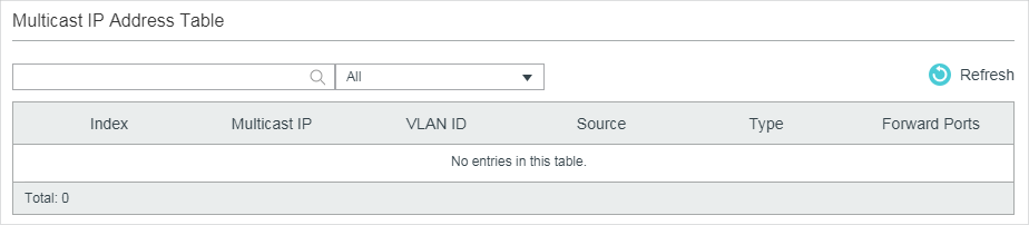
The multicast IP address table shows all valid Multicast IP-VLAN-Port entries:
|
Multicast IP |
Displays the multicast source IP address. |
|
VLAN ID |
Displays the ID of the VLAN the multicast group belongs to. |
|
Source |
Displays the source of the multicast entry. IGMP Snooping: The multicast entry is learned by IGMP Snooping. MVR: The multicast entry is learned by MVR. |
|
Type |
Displays how the multicast entry is generated. Dynamic: The entry is dynamically learned. All the member ports are dynamically added to the multicast group. Static: The entry is manually added. All the member ports are manually added to the multicast group. Mix: The entry is dynamically learned (manually learned), and some of the member ports are manually added (dynamically added) to the multicast group. |
|
Forward Ports |
All ports in the multicast group, including router ports and member ports. |
6.1.2Viewing IPv4 Multicast Statistics on Each Port
Choose the menu L2 FEATURES > Multicast > Multicast Info > IPv4 Multicast Statistics to load the following page:
Figure 6-2 IPv4 Multicast Statistics
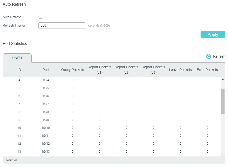
Follow these steps to view IPv4 multicast statistics on each port:
1)To get the real-time multicast statistics, enable Auto Refresh, or click Refresh.
|
Auto Refresh |
Enable or disable Auto Refresh. When enabled, the switch will automatically refresh the multicast statistics. |
|
Refresh Interval |
After Auto Refresh is enabled, specify the time interval for the switch to refresh the multicast statistics. |
2)In the Port Statistics section, view IPv4 multicast statistics on each port.
|
Query Packets |
Displays the number of query packets received by the port. |
|
Report Packets (v1) |
Displays the number of IGMPv1 report packets received by the port. |
|
Report Packets (v2) |
Displays the number of IGMPv2 report packets received by the port. |
|
Report Packets (v3) |
Displays the number of IGMPv3 report packets received by the port. |
|
Leave Packets |
Displays the number of leave packets received by the port. |
|
Error Packets |
Displays the number of error packets received by the port. |
6.1.3Viewing IPv6 Multicast Table
Choose the menu L2 FEATURES > Multicast > Multicast Info > IPv6 Multicast Table to load the following page:
Figure 6-3 IPv6 Multicast Table
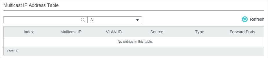
The multicast IP address table shows all valid Multicast IP-VLAN-Port entries:
|
Multicast IP |
Displays the multicast source IP address. |
|
VLAN ID |
Displays the ID of the VLAN the multicast group belongs to. |
|
Source |
Displays the source of the multicast entry. MLD Snooping: The multicast entry is learned by IGMP Snooping. |
|
Type |
Displays how the multicast entry is generated. Dynamic: The entry is dynamically learned. All the member ports are dynamically added to the multicast group. Static: The entry is manually added. All the member ports are manually added to the multicast group. Mix: The entry is dynamically learned (manually learned), and some of the member ports are manually added (dynamically added) to the multicast group. |
|
Forward Port |
All ports in the multicast group, including router ports and member ports. |
6.1.4Viewing IPv6 Multicast Statistics on Each Port
Choose the menu L2 FEATURES > Multicast > Multicast Info > IPv6 Multicast Statistics to load the following page:
Figure 6-4 IPv6 Multicast Statistics
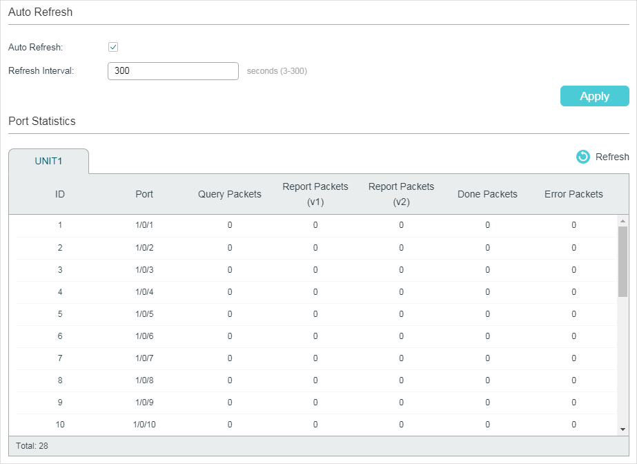
Follow these steps to view IPv6 multicast statistics on each port:
1)To get the real-time IPv6 multicast statistics, enable Auto Refresh, or click Refresh.
|
Auto Refresh |
Enable or disable Auto Refresh. When enabled, the switch will automatically refresh the multicast statistics. |
|
Refresh Interval |
After Auto Refresh is enabled, specify the time interval for the switch to refresh the multicast statistics. |
2)In the Port Statistics section, view IPv6 multicast statistics on each port.
|
Query Packets |
Displays the number of query packets received by the port. |
|
Report Packets (v1) |
Displays the number of MLDv1 packets received by the port. |
|
Report Packets (v2) |
Displays the number of MLDv2 packets received by the port. |
|
Done Packets |
Displays the number of done packets received by the port. |
|
Error Packets |
Displays the number of error packets received by the port. |
6.2Using the CLI
6.2.1Viewing IPv4 Multicast Snooping Information
|
show ip igmp snooping groups [ vlan vlan-id ] [count | dynamic | dynamic count | static | static count ] Displays information of specific multicast group in all VLANs or in the specific VLAN. count: Displays the number of multicast groups. dynamic: Displays information of all dynamic multicast groups. dynamic count: Displays the number of dynamic multicast groups. static: Displays information of all static multicast groups. static count: Displays the number of static multicast groups. |
|
show ip igmp snooping interface [ fastEthernet [ port-list ] | gigabitEthernet [ port-list ] | ten-gigabitEthernet [ port-list ] ] packet-stat Displays the packet statistics on specified ports or all ports. |
|
clear ip igmp snooping statistics Clear all statistics of all IGMP packets. |
6.2.2Viewing IPv6 Multicast Snooping Configurations
|
show ipv6 mld snooping groups [vlan vlan-id ] [count | dynamic | dynamic count | static | static count ] Displays information of specific multicast group in all VLANs or in the specific VLAN. count displays the number of multicast groups. dynamic displays information of all dynamic multicast groups. dynamic count displays the number of dynamic multicast groups. static displays information of all static multicast groups. static count displays the number of static multicast groups. |
|
show ipv6 mld snooping interface [ fastEthernet [ port-list ] | gigabitEthernet [ port-list ] | ten-gigabitEthernet [ port-list ] ] packet-stat Displays the packet statistics on specified ports or all ports. |
|
clear ipv6 mld snooping statistics Clear all statistics of all MLD packets. |
7.1Example for Configuring Basic IGMP Snooping
7.1.1Network Requirements
Host B, Host C and Host D are in the same VLAN of the switch. All of them want to receive multicast streams sent to multicast group 225.1.1.1.
As shown in the following topology, Host B, Host C and Host D are connected to port 1/0/1, port 1/0/2 and port 1/0/3 respectively. Port 1/0/4 is the router port connected to the multicast querier.
Figure 7-1 Network Topology for Basic IGMP Snooping
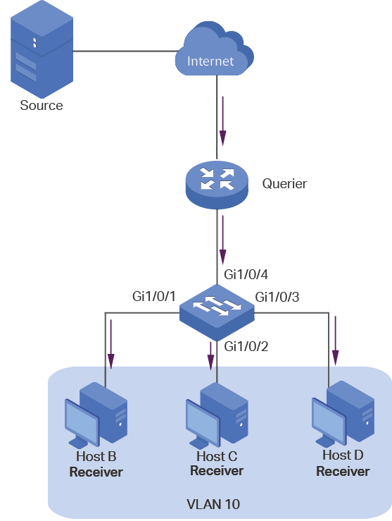
7.1.2Configuration Scheme
Add the three member ports and the router port to a VLAN and configure their PVIDs.
Enable IGMP Snooping globally and in the VLAN.
Enable IGMP Snooping on the ports.
Demonstrated with T2600G-28TS, this section provides configuration procedures in two ways: using the GUI and using the CLI.
7.1.3Using the GUI
1)Choose the menu L2 FEATURES > VLAN > 802.1Q VLAN > VLAN Config and click to load the following page. Create VLAN 10 and add Untagged port 1/0/1-3 and Tagged port 1/0/4 to VLAN 10.
Figure 7-2 Create VLAN 10
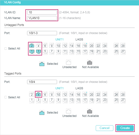
2)Choose the menu L2 FEATURES > VLAN > 802.1Q VLAN > Port Config to load the following page. Configure the PVID of port 1/0/1-4 as 10.
Figure 7-3 Configure PVID for the Ports
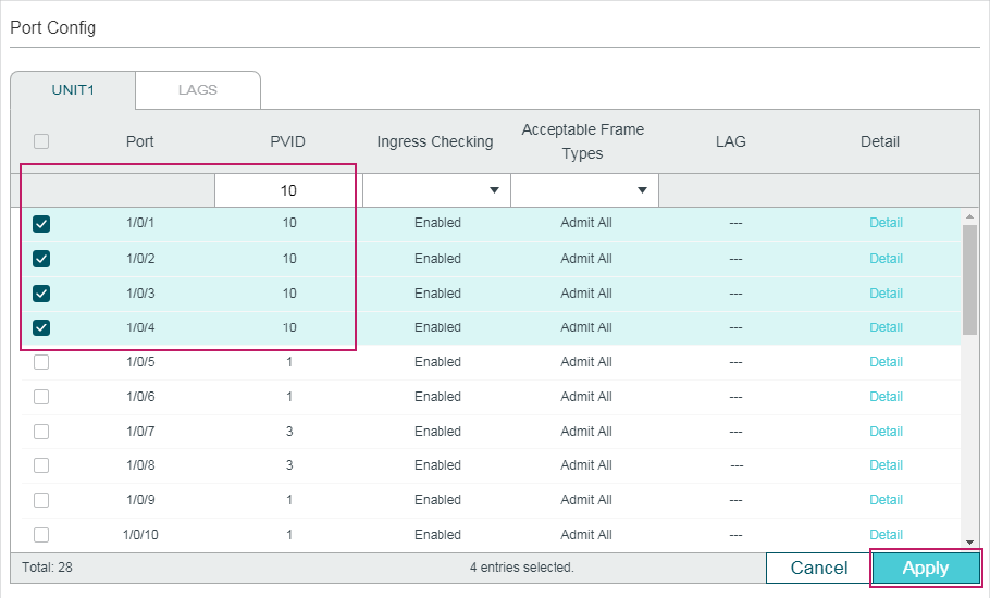
3)Choose the menu L2 FEATURES > Multicast > IGMP Snooping > Global Config to load the following page. In the Global Config section, enable IGMP Snooping globally. Configure the IGMP version as v3 so that the switch can process IGMP messages of all versions. Then click Apply.
Figure 7-4 Configure IGMP Snooping Globally
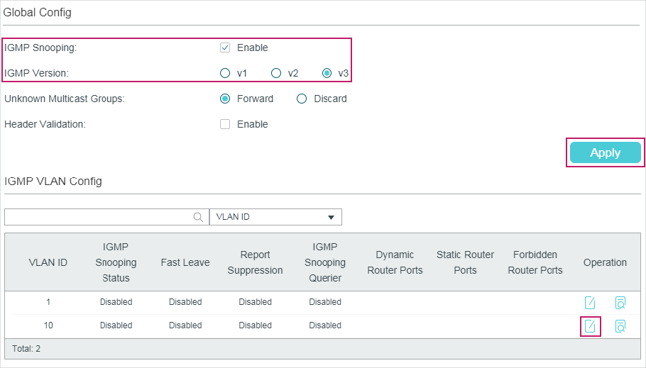
4)In the IGMP VLAN Config section, click in VLAN 10 to load the following page. Enable IGMP Snooping for VLAN 10.
Figure 7-5 Enable IGMP Snooping for VLAN 10
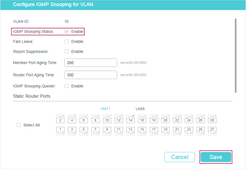
5)Choose the menu L2 FEATURES > Multicast > IGMP Snooping > Port Config to load the following page. Enable IGMP Snooping for ports 1/0/1-4.
Figure 7-6 Enable IGMP Snooping for the Ports
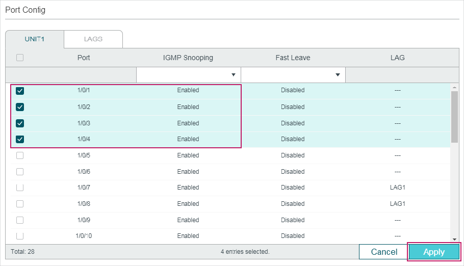
6)Click  to save the settings.
7.1.4Using the CLI
1)Create VLAN 10.
Switch#configure
Switch(config)#vlan 10
Switch(config-vlan)#name vlan10
Switch(config-vlan)#exit
2)Add port 1/0/1-3 to VLAN 10 and set the link type as untagged. Add port 1/0/4 to VLAN 10 and set the link type as tagged.
Switch(config)#interface range gigabitEthernet 1/0/1-3
Switch(config-if-range)#switchport general allowed vlan 10 untagged
Switch(config-if-range)#exit
Switch(config)#interface gigabitEthernet 1/0/4
Switch(config-if)#switchport general allowed vlan 10 tagged
Switch(config-if)#exit
3)Set the PVID of port 1/0/1-4 as 10.
Switch(config)#interface range gigabitEthernet 1/0/1-4
Switch(config-if-range)#switchport pvid 10
Switch(config-if-range)#exit
4)Enable IGMP Snooping globally.
Switch(config)#ip igmp snooping
5)Enable IGMP Snooping in VLAN 10.
Switch(config)#ip igmp snooping vlan-config 10
6)Enable IGMP Snooping on port 1/0/1-4.
Switch(config)#interface range gigabitEthernet 1/0/1-4
Switch(config-if-range)#ip igmp snooping
Switch(config-if-range)#exit
7)Save the settings.
Switch(config)#end
Switch#copy running-config startup-config
Verify the Configurations
Show members in the VLAN:
Switch(config)#show vlan brief
VLAN Name Status Ports
----- -------------------- --------- ----------------------------------------
1 System-VLAN active Gi1/0/1, Gi1/0/2, Gi1/0/3, Gi1/0/4,
Gi1/0/5, Gi1/0/6, Gi1/0/7, Gi1/0/8,
...
10 vlan10 active Gi1/0/1, Gi1/0/2, Gi1/0/3, Gi1/0/4
Show status of IGMP Snooping globally, on the ports and in the VLAN:
Switch(config)#show ip igmp snooping
IGMP Snooping :Enable
IGMP Version :V3
Header Validation :Disable
Global Authentication Accounting :Disable
Enable Port : Gi1/0/1-4
Enable VLAN:10
7.2Example for Configuring MVR
7.2.1Network Requirements
Host B, Host C and Host D are in three different VLANs of the switch. All of them want to receive multicast streams sent to multicast group 225.1.1.1.
7.2.2Network Topology
As shown in the following network topology, Host B, Host C and Host D are connected to port 1/0/1, port 1/0/2 and port 1/0/3 respectively. Port 1/0/1, port 1/0/2 and port 1/0/3 belong to VLAN 10, VLAN 20 and VLAN 30 respectively. Port 1/0/4 is connected to the multicast network in the upper layer network.
Figure 7-7 Network Topoloy for Multicast VLAN
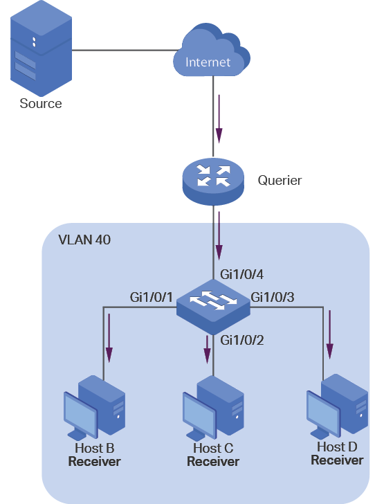
7.2.3Configuration Scheme
As the hosts are in different VLANs, in IGMP Snooping, the Querier need to duplicate multicast streams for hosts in each VLAN. To avoid duplication of multicast streams being sent between Querier and the switch, you can configure MVR on the switch.
The switch can work in either MVR compatible mode or MVR dynamic mode. When in compatible mode, remember to statically configure the Querier to transmit the streams of multicast group 225.1.1.1 to the switch via the multicast VLAN. Here we take the MVR dynamic mode as an example.
Demonstrated with T2600G-28TS, this section provides configuration procedures in two ways: using the GUI and using the CLI.
7.2.4Using the GUI
1)Add port 1/0/1-3 to VLAN 10, VLAN 20 and VLAN 30 as Untagged ports respectively, and configure the PVID of port 1/0/1 as 10, port 1/0/2 as 20, port 1/0/3 as 30. Make sure port1/0/1-3 only belong to VLAN 10, VLAN 20 and VLAN 30 respectively. For details, refer to Configuring 802.1Q VLAN.
Figure 7-8 VLAN Configurations for Port 1/0/1-3
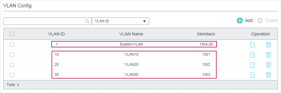
Figure 7-9 PVID for Port 1/0/1-3
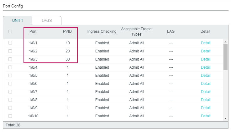
2)Choose the menu L2 FEATURES > VLAN > 802.1Q VLAN > VLAN Config and click to load the following page. Create VLAN 40 and add port 1/0/4 to the VLAN as Tagged port.
Figure 7-10 Create Multicast VLAN
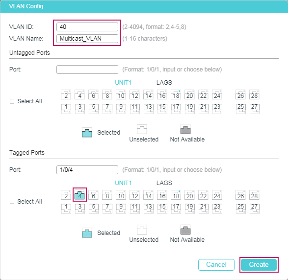
3)Choose the menu L2 FEATURES > Multicast > MVR > MVR Config to load the following page. Enable MVR globally, and configure the MVR mode as Dynamic, multicast VLAN ID as 40.
Figure 7-11 Configure MVR Globally
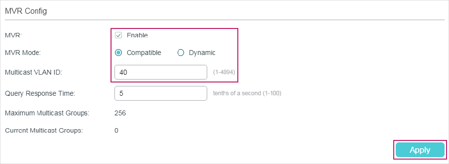
4)Choose the menu L2 FEATURES > Multicast > MVR > MVR Group Config and click  to load the following page. Add multicast group 225.1.1.1 to MVR.
Figure 7-12 Add Multicast Group to MVR
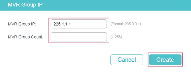
5)Choose the menu L2 FEATURES > Multicast > MVR > Port Config to load the following page. Enable MVR for port 1/0/1-4. Configure port 1/0/1-3 as Receiver ports and port 1/0/4 as Source port.
Figure 7-13 Configure MVR for the Ports
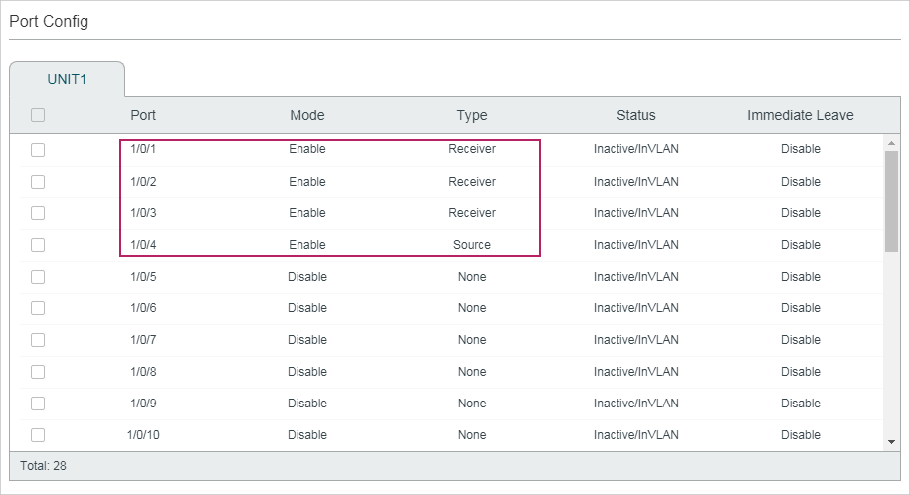
6)Click  to save the settings.
7.2.5Using the CLI
1)Create VLAN 10, VLAN 20, VLAN 30 and VLAN 40.
Switch#configure
Switch(config)#vlan 10,20,30,40
Switch(config-vlan)#exit
2)Add port 1/0/1-3 to VLAN 10, VLAN 20 and VLAN 30 as untagged ports respectively, and configure the PVID of port 1/0/1 as 10, port 1/0/2 as 20, port 1/0/3 as 30. Add port 1/0/4 to VLAN 40 as tagged port and configure the PVID as of port 1/0/4 as 40.
Switch(config)#interface gigabitEthernet 1/0/1
Switch(config-if)#switchport general allowed vlan 10 untagged
Switch(config-if)#switchport pvid 10
Switch(config-if)#exit
Switch(config)#interface gigabitEthernet 1/0/2
Switch(config-if)#switchport general allowed vlan 20 untagged
Switch(config-if)#switchport pvid 20
Switch(config-if)#exit
Switch(config)#interface gigabitEthernet 1/0/3
Switch(config-if)#switchport general allowed vlan 30 untagged
Switch(config-if)#switchport pvid 30
Switch(config-if)#exit
Switch(config)#interface gigabitEthernet 1/0/4
Switch(config-if)#switchport general allowed vlan 40 tagged
Switch(config-if)#switchport pvid 40
Switch(config-if)#exit
3)Check whether port1/0/1-3 only belong to VLAN 10, VLAN 20 and VLAN 30 respectively. If not, delete them from the other VLANs. By default, all ports are in VLAN 1, so you need to delete them from VLAN 1.
Switch(config)#show vlan brief
VLAN Name Status Ports
------- ---------------- --------- ----------------------------------------
1 System-VLAN active Gi1/0/1, Gi1/0/2, Gi1/0/3, Gi1/0/4,
Gi1/0/5, Gi1/0/6, Gi1/0/7, Gi1/0/8,
...
10 VLAN10 active Gi1/0/1
20 VLAN20 active Gi1/0/2
30 VLAN30 active Gi1/0/3
40 VLAN40 active Gi1/0/4
Switch(config)#interface range gigabitEthernet 1/0/1-3
Switch(config-if-range)#no switchport general allowed vlan 1
Switch(config-if-range)#exit
4)Enable MVR globally, and configure the MVR mode as Dynamic, multicast VLAN ID as 40. Add multicast group 225.1.1.1 to MVR.
Switch(config)#mvr
Switch(config)#mvr mode dynamic
Switch(config)#mvr vlan 40
Switch(config)#mvr group 225.1.1.1 1
5)Enable MVR for port 1/0/1-4. Configure port 1/0/1-3 as Receiver ports and port 1/0/4 as Source port.
Switch(config)#interface range gigabitEthernet 1/0/1-3
Switch(config-if-range)#mvr
Switch(config-if-range)#mvr type receiver
Switch(config-if-range)#exit
Switch(config)#interface gigabitEthernet 1/0/4
Switch(config-if)#mvr
Switch(config-if)#mvr type source
Switch(config-if)#exit
6)Save the settings.
Switch(config)#end
Switch#copy running-config startup-config
Verify the Configurations
Show the brief information of all VLANs:
Switch(config)#show vlan brief
VLAN Name Status Ports
------- ---------------- --------- ----------------------------------------
1 System-VLAN active Gi1/0/4, Gi1/0/5, Gi1/0/6, Gi1/0/7,
...
10 VLAN10 active Gi1/0/1
20 VLAN20 active Gi1/0/2
30 VLAN30 active Gi1/0/3
40 VLAN40 active Gi1/0/4
Show the brief information of MVR:
Switch(config)#show mvr
MVR :Enable
MVR Multicast Vlan :40
MVR Max Multicast Groups :256
MVR Current Multicast Groups :1
MVR Global Query Response Time :5 (tenths of sec)
MVR Mode Type :Dynamic
Show the membership of MVR groups:
Switch(config)#show mvr members
MVR Group IP Status Members
----------------- ------------ ------------------
225.1.1.1 active Gi1/0/4
7.3Example for Configuring Unknown Multicast and Fast Leave
7.3.1Network Requirement
A user experiences lag when he is changing channel on his IPTV. He wants solutions to this problem. As shown in the following network topology, port 1/0/4 on the switch is connected to the upper layer network, and port 1/0/2 is connected to Host B.
Figure 7-14 Network Topology for Unknow Multicast and Fast Leave
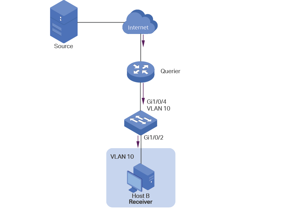
7.3.2Configuration Scheme
After the channel is changed, the client (Host B) still receives irrelevant multicast data, the data from the previous channel and possibly other unknown multicast data, which increases the network load and results in network congestion.
To avoid Host B from receiving irrelevant multicast data, you can enable Fast Leave on port 1/0/2 and configure the switch to discard unknown multicast data. To change channel, Host B sends a leave message about leaving the previous channel. With Fast Leave enabled on port 1/0/2, the switch will then drop multicast data from the previous channel, which ensures that Host B only receives multicast data from the new channel and that the multicast network is unimpeded.
Demonstrated with T2600G-28TS, this section provides configuration procedures in two ways: using the GUI and using the CLI.
7.3.3Using the GUI
1)Create VLAN 10. Add port 1/0/2 to the VLAN as untagged port and port 1/0/4 as tagged port. Configure the PVID of the two ports as 10. For details, refer to Configuring 802.1Q VLAN.
2)Choose the menu L2 FEATURES > Multicast > IGMP Snooping > Global Config to load the following page. In the Global Config section, enable IGMP Snooping globally and configure Unknown Multicast Groups as Discard.
Figure 7-15 Configure IGMP Snooping Globally
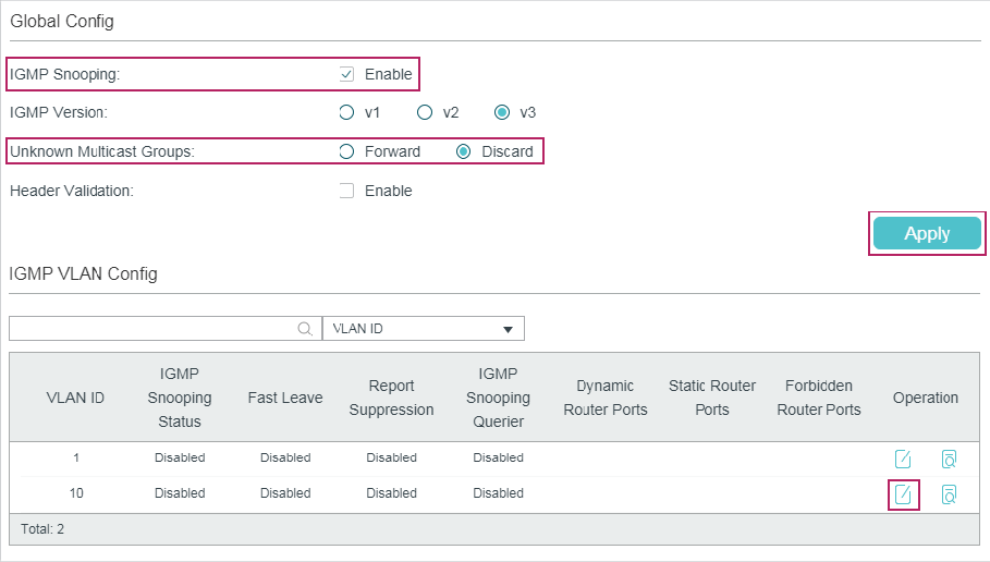
|
|
Note: IGMP Snooping and MLD Snooping share the setting of Unknown Multicast, so you have to enable MLD Snooping globally on the L2 FEATURES > Multicast > MLD Snooping > Global Config page at the same time. |

3)In the IGMP VLAN Config section, click  in VLAN 10 to load the following page. Enable IGMP Snooping for VLAN 10.
Figure 7-16 Enable IGMP Snooping for VLAN 10
4)Choose the menu L2 FEATURES > Multicast > IGMP Snooping > Port Config to load the following page. Enable IGMP Snooping on port 1/0/2 and port 1/0/4 and enable Fast Leave on port 1/0/2.
Figure 7-17 Configure IGMP Snooping on Ports
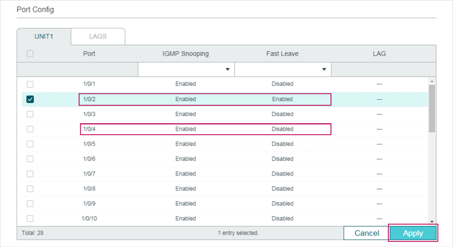
5)Click to save the settings.
7.3.4Using the CLI
1)Enable IGMP Snooping and MLD Snooping globally.
Switch#configure
Switch(config)#ip igmp snooping
Switch(config)#ipv6 mld snooping
2)Configure Unknown Multicast Groups as Discard globally.
Switch(config)#ip igmp snooping drop-unknown
3)Enable IGMP Snooping on port 1/0/2 and enable Fast Leave. On port 1/0/4, enable IGMP Snooping.
Switch(config)#interface gigabitEthernet 1/0/2
Switch(config-if)#ip igmp snooping
Switch(config-if)#ip igmp snooping immediate-leave
Switch(config-if)#exit
Switch(config)#interface gigabitEthernet 1/0/4
Switch(config-if)#ip igmp snooping
Switch(config-if)#exit
4)Enable IGMP Snooping in VLAN 10.
Switch(config)#ip igmp snooping vlan-config 10
5)Save the settings.
Switch(config)#end
Switch#copy running-config startup-config
Verify the Configurations
Show global settings of IGMP Snooping:
Switch(config)#show ip igmp snooping
IGMP Snooping :Enable
IGMP Version :V3
Unknown Multicast :Discard
...
Enable Port: Gi1/0/1-28
Enable VLAN:10
Show settings of IGMP Snooping on port 1/0/2:
Switch(config)#show ip igmp snooping interface gigabitEthernet 1/0/2 basic-config
Port IGMP-Snooping Fast-Leave
--------- ------------------- ----------
Gi1/0/2 enable enable
7.4Example for Configuring Multicast Filtering
7.4.1Network Requirements
Host B, Host C and Host D are in the same subnet. Host C and Host D only receive multicast data sent to 225.0.0.1, while Host B receives all multicast data except the one sent from 225.0.0.2.
7.4.2Configuration Scheme
With the functions for managing multicast groups, whitelist and blacklist mechanism (profile binding), the switch can only allow specific member ports to join specific multicast groups or disallow specific member ports to join specific multicast groups. You can achieve this filtering function by creating a profile and binding it to the corresponding member port.
7.4.3Network Topology
As shown in the following network topology, Host B is connected to port 1/0/1, Host C is connected to port 1/0/2 and Host D is connected to port 1/0/3. They are all in VLAN 10.
Figure 7-18 Network Topology for Multicast Filtering
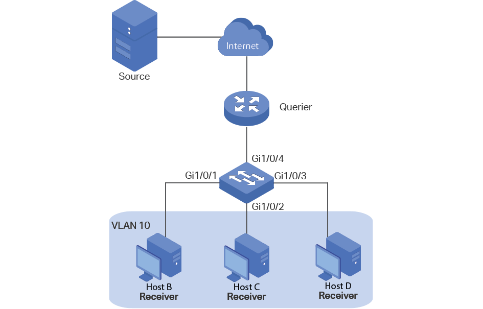
Demonstrated with T2600G-28TS, this section provides configuration procedures in two ways: using the GUI and using the CLI.
7.4.4Using the GUI
1)Create VLAN 10. Add port 1/0/1-3 to the VLAN as untagged port and port 1/0/4 as tagged port. Configure the PVID of the four ports as 10. For details, refer to Configuring 802.1Q VLAN.
2)Choose the menu L2 FEATURES > Multicast > IGMP Snooping > Global Config to load the following page. In the Global Config section, enable IGMP Snooping globally.
Figure 7-19 Enable IGMP Snooping Globally
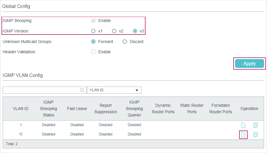
3)In the IGMP VLAN Config section, click  in VLAN 10 to load the following page. Enable IGMP Snooping for VLAN 10.
Figure 7-20 Enable IGMP Snooping for VLAN 10
4)Choose the menu L2 FEATURES > Multicast > IGMP Snooping > Port Config to load the following page.
Figure 7-21 Enable IGMP Snooping on the Port
5)Choose the menu L2 FEATURES > Multicast > Multicast Filtering > IPv4 Profile and click to load the following page. Create Profile 1, specify the mode as Permit, bind the profile to port 1/0/2-3, and specify the filtering multicast IP address as 225.0.0.1. Then click Back to return to the IPv4 Profile Table page.
Figure 7-22 Configure Filtering Profile for Host C and Host D
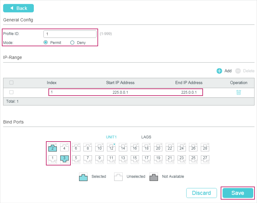
6)Click again to load the following page. Create Profile 2, specify the mode as Deny, bind the profile to port 1/0/1, and specify the filtering multicast IP address as 225.0.0.2.
Figure 7-23 Configure Filtering Profile for Host B
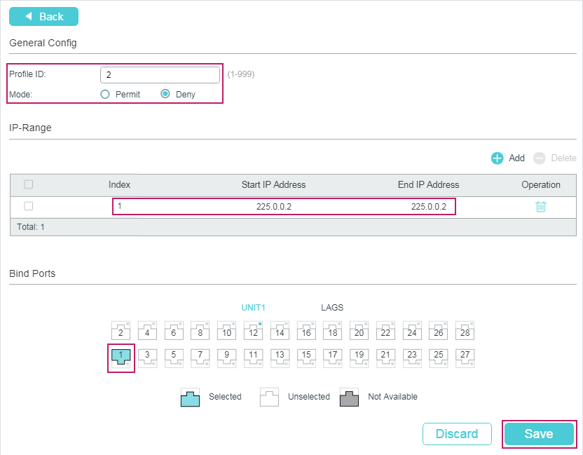
7)Click to save the settings.
7.4.5Using the CLI
1)Create VLAN 10.
Switch#configure
Switch(config)#vlan 10
Switch(config-vlan)#name vlan10
Switch(config-vlan)#exit
2)Add port 1/0/1-3 to VLAN 10 and set the link type as untagged. Add port 1/0/4 to VLAN 10 and set the link type as tagged.
Switch(config)#interface range gigabitEthernet 1/0/1-3
Switch(config-if-range)#switchport general allowed vlan 10 untagged
Switch(config-if-range)#exit
Switch(config)#interface gigabitEthernet 1/0/4
Switch(config-if)#switchport general allowed vlan 10 tagged
Switch(config-if)#exit
3)Set the PVID of port 1/0/1-4 as 10.
Switch(config)#interface range gigabitEthernet 1/0/1-4
Switch(config-if-range)#switchport pvid 10
Switch(config-if-range)#exit
4)Enable IGMP Snooping Globally.
Switch(config)#ip igmp snooping
5)Enable IGMP Snooping in VLAN 10.
Switch(config)#ip igmp snooping vlan-config 10
6)Enable IGMP Snooping on port 1/0/1-4.
Switch(config)#interface range gigabitEthernet 1/0/1-4
Switch(config-if-range)#ip igmp snooping
Switch(config-if-range)#exit
7)Create Profile 1, configure the mode as permit, and add an IP range with both start IP and end IP being 225.0.0.1.
Switch(config)#ip igmp profile 1
Switch(config-igmp-profile)#permit
Switch(config-igmp-profile)#range 225.0.0.1 225.0.0.1
Switch(config-igmp-profile)#exit
8)Bind Profile 1 to Port 1/0/2 and Port 1/10/3.
Switch(config)#interface range gigabitEthernet 1/0/2-3
Switch(config-if-range)#ip igmp filter 1
Switch(config-if-range)#exit
9)Create Profile 2, configure the mode as deny, and add an IP range with both start IP and end IP being 225.0.0.2.
Switch(config)#ip igmp profile 2
Switch(config-igmp-profile)#deny
Switch(config-igmp-profile)#range 225.0.0.2 225.0.0.2
Switch(config-igmp-profile)#exit
10)Bind Profile 2 to Port 1/0/1.
Switch(config)#interface gigabitEthernet 1/0/1
Switch(config-if)#ip igmp filter 2
Switch(config-if)#exit
11)Save the settings.
Switch(config)#end
Switch#copy running-config startup-config
Verify the Configurations
Show global settings of IGMP Snooping:
Switch(config)#show ip igmp snooping
IGMP Snooping :Enable
IGMP Version :V3
...
Enable Port:Gi1/0/1-4
Enable VLAN:10
Show all profile bindings:
Switch(config)#show ip igmp profile
IGMP Profile 1
permit
range 225.0.0.1 225.0.0.1
Binding Port(s)
Gi1/0/2-3
IGMP Profile 2
deny
range 225.0.0.2 225.0.0.2
Binding Port(s)
Gi1/0/1
8.1Default Parameters for IGMP Snooping
Table 8-1Default Parameters of IGMP Snooping
|
Function |
Parameter |
Default Setting |
|
Global Settings of IGMP Snooping |
IGMP Snooping |
Disabled |
|
IGMP Version |
v3 |
|
|
Unknown Multicast Groups |
Forward |
|
|
Header Validation |
Disabled |
|
|
IGMP Snooping Settings in the VLAN |
IGMP Snooping |
Disabled |
|
Fast Leave |
Disabled |
|
|
Report Suppression |
Disabled |
|
|
Member Port Aging Time |
260 seconds |
|
|
Router Port Aging Time |
300 seconds |
|
|
Leave Time |
1 second |
|
|
IGMP Snooping Querier |
Disabled |
|
|
Query Interval |
60 seconds |
|
|
Maximum Response Time |
10 seconds |
|
|
Last Member Query Interval |
1 second |
|
|
Last Member Query Count |
2 |
|
|
General Query Source IP |
0.0.0.0 |
|
|
Static Router Ports |
None |
|
|
Forbidden Router Ports |
None |
|
|
IGMP Snooping Settings on the Port and LAG |
IGMP Snooping |
Enabled |
|
Fast Leave |
Disabled |
|
|
Static Multicast Group Settings |
Static Multicast Group Entries |
None |
|
IGMP Accounting and Authentication |
IGMP Accounting |
Disabled |
|
IGMP Authentication |
Disabled |
8.2Default Parameters for MLD Snooping
Table 8-2Default Parameters of MLD Snooping
|
Function |
Parameter |
Default Setting |
|
Global Settings of IGMP Snooping |
MLD Snooping |
Disabled |
|
Unknown Multicast Groups |
Forward |
|
|
MLD Snooping Settings in the VLAN |
MLD Snooping |
Disabled |
|
Fast Leave |
Disabled |
|
|
Report Suppression |
Disabled |
|
|
Member Port Aging Time |
260 seconds |
|
|
Router Port Aging Time |
300 seconds |
|
|
Leave Time |
1 second |
|
|
MLD Snooping Querier |
Disabled |
|
|
Query Interval |
60 seconds |
|
|
Maximum Response Time |
10 seconds |
|
|
Last Listener Query Interval |
1 second |
|
|
Last Listener Query Count |
2 |
|
|
General Query Source IP |
:: |
|
|
Static Router Ports |
None |
|
|
Forbidden Router Ports |
None |
|
|
MLD Snooping Settings on the Port and LAG |
MLD Snooping |
Enabled |
|
Fast Leave |
Disabled |
|
|
Static Multicast Group Settings |
Static Multicast Group Entries |
None |
8.3Default Parameters for MVR
Table 8-3Default Parameters of MVR
|
Function |
Parameter |
Default Setting |
|
Global Settings of MVR |
MVR |
Disabled |
|
MVR Mode |
Compatible |
|
|
Multicast VLAN ID |
1 |
|
|
Query Response Time |
5 tenths of a second |
|
|
Maximum Multicast Groups |
256 |
|
|
MVR Group Settings |
MVR Group Entries |
None |
|
MVR Settings on the Port |
MVR Mode |
Disabled |
|
MVR Port Type |
None |
|
|
Fast Leave |
Disabled |
|
|
MVR Static Group Members |
MVR Static Group Member Entries |
None |
8.4Default Parameters for Multicast Filtering
Table 8-4Default Parameters of Multicast Filtering
|
Function |
Parameter |
Default Setting |
|
Profile Settings |
IPv4 Profile and IPv6 Profile Entries |
None |
|
Multicast Filtering Settings on the Port and LAG |
Bound Profile |
None |
|
Maximum Groups |
For T2600G and T1600G series switches except T1600G-28TS V3, the default value is 1000. For other switches, the default value is 511. |
|
|
Overflow Action |
Drop |