Configuring Layer 3 Interfaces
CHAPTERS
2. Layer 3 Interface Configurations
4. Appendix: Default Parameters
|
|
This guide applies to: T1600G-18TS v2 or above, T1600G-28TS v3 or above, T1600G-28PS v3 or above, T1600G-52TS v3 or above, T1600G-52PS v3 or above, T1700X-16TS v3 or above, T1700G-28TQ v3 or above, T2600G-18TS v2 or above, T2600G-28TS v3 or above, T2600G-28MPS v3 or above, T2600G-28SQ v1 or above, T2600G-52TS v3 or above. |

Interfaces are used to exchange data and interact with interfaces of other network devices. Interfaces are classified into Layer 2 interfaces and Layer 3 interfaces.
Layer 2 interfaces are the physical ports on the switch panel. They forward packets based on MAC address table.
Layer 3 interfaces are used to forward IPv4 and IPv6 packets using static or dynamic routing protocols. You can use Layer 3 interfaces for IP routing and inter-VLAN routing.
This chapter introduces the configurations for Layer 3 interfaces. The supported types of Layer 3 interfaces are shown as below:
Table 1-1Supported Types of Layer 3 interfaces
|
Type |
Description |
|
VLAN Interface |
A Layer 3 interface with which acts as the default gateway of all the hosts in the corresponding VLAN. |
|
Loopback Interface |
An interface of which the status is always up. |
|
Routed Port |
A physical port configured as a Layer 3 port. |
|
Port-channel Interface |
Several routed ports are bound together and configured as a Layer 3 interface. |
2Layer 3 Interface Configurations
To complete IPv4 interface configuration, follow these steps:
1)Create a Layer 3 interface
2)Configure IPv4 parameters of the created interface
3)View detailed information of the created interface
To complete IPv6 interface configuration, follow these steps:
1)Create a Layer 3 interface
2)Configure IPv6 parameters of the created interface
3)View detailed information of the created interface
2.1.1Creating a Layer 3 Interface
Choose the menu L3 FEATURES> Interface to load the following page.
Figure 2-1 Creating a Layer 3 Interface
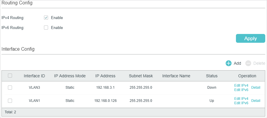
Follow these steps to create a Layer 3 interface.
1)In the Routing Config section, enable IPv4 routing or IPv6 routing. Then click Apply.
|
IPv4 Routing |
Enable IPv4 routing function globally for all Layer 3 interfaces. It is enabled by default. |
|
IPv6 Routing |
(Optional) Enable IPv6 routing function globally for all Layer 3 interfaces. It is disabled by default. |
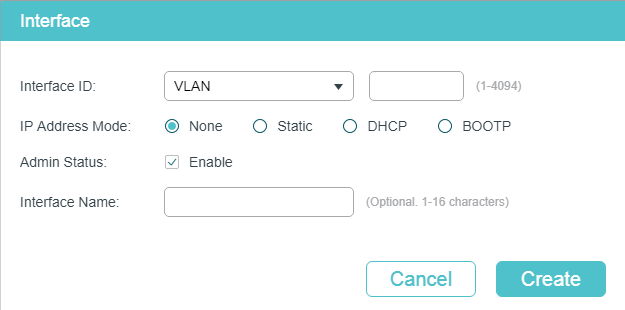
2)In the Interface Config section, click  to load the following page, and configure the corresponding parameters for the Layer 3 interface. Then click Create.
|
Interface ID |
Select an interface type and enter the ID of the interface. |
|
IP Address Mode |
Specify the IP address assignment mode of the interface. None: No IP address will be assigned to the interface. Static: Assign an IP address to the interface manually. DHCP: Assign an IP address to the interface through the DHCP server. BOOTP: Assign an IP address to the interface through the BOOTP server. |
|
DHCP Option 12 |
If you select DHCP as the IP Address Mode, configure the Option 12 here. DHCP Option 12 is used to specify the client’s name. |
|
IP Address |
Specify the IP address of the interface if you choose “Static” as the IP address assignment mode. |
|
Subnet Mask |
Specify the subnet mask of the interface’s IP address. |
|
Admin Status |
Enable or disable the interface’s Layer 3 capabilities. |
|
Interface Name |
(Optional) Enter a name for the interface. |
|
|
Note: The created interface is an IPv4 interface. To configure the IPv6 features, please click “Edit IPv6“ after the interface is created. |

2.1.2Configuring IPv4 Parameters of the Interface
In Figure 2-1, you can view the corresponding interface you have created in the Interface Config section. On the corresponding interface entry, click Edit IPv4 to load the following page and edit the IPv4 parameters of the interface.
Figure 2-2 Configuring the IPv4 Parameters
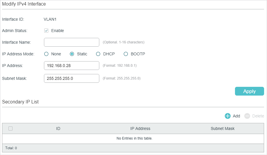
1)In the Modify IPv4 Interface section, configure relevant parameters for the interface according to your actual needs. Then click Apply.
|
Interface ID |
Displays the interface ID. |
|
Admin Status |
Enable the Layer 3 capabilities for the interface. |
|
Interface Name |
(Optional) Enter a name for the interface. |
|
IP Address Mode |
Specify the IP address assignment mode of the interface. None: No IP address will be assigned. Static: Assign an IP address manually. DHCP: Obtain an IP address through DHCP. BOOTP: Obtain an IP address through BOOTP. |
|
IP Address |
Specify the IP address of the interface if you choose “Static” as the IP address assignment mode. |
|
Subnet Mask |
Specify the subnet mask of the interface’s IP address. |
|
DHCP Option 12 |
If you select DHCP as the IP Address Mode, configure the Option 12 here. DHCP Option 12 is used to specify the client’s name. |
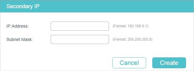
2)In the Secondary IP Table section, click to add a secondary IP for the specified interface which allows you to have two logical subnets. Then click Create.
|
IP Address |
Specify the secondary IP address of the interface. |
|
Subnet Mask |
Specify the subnet mask of the secondary IP address. |
3)(Optional) In the Secondary IP Table section, you can view the corresponding secondary IP entry you have created.
2.1.3Configuring IPv6 Parameters of the Interface
In Figure 2-1, you can view the corresponding interface entry you have created in the Interface Config section. On the corresponding interface entry, click Edit IPv6 to load the following page and configure the IPv6 parameters of the interface.
Figure 2-3 Configuring the IPv6 Parameters
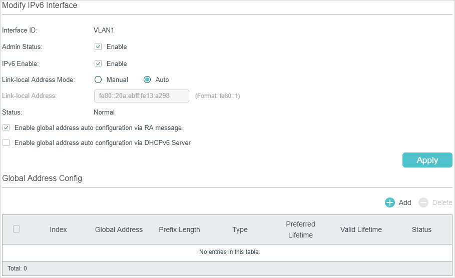
1)In the Modify IPv6 Interface section, enable IPv6 feature for the interface and configure the corresponding parameters . Then click Apply.
|
Interface ID |
Displays the interface ID. |
|
Admin Status |
Enable the Layer 3 capabilities for the interface. |
|
IPv6 Enable |
Enable the IPv6 feature of the interface. |
|
Link-local Address Mode |
Select the link-local address configuration mode. Manual: With this option selected, you can assign a link-local address manually. Auto: With this option selected, the switch generates a link-local address automatically. |
|
Link-local Address |
Enter a link-local address if you choose “Manual” as the Link-Local Address Mode. |
|
Status |
Displays the status of the link-local address. An IPv6 address cannot be used before pass the DAD (Duplicate Address Detection), which is used to detect the address conflicts. In the DAD process, the IPv6 address may in three different status: Normal: Indicates that the link-local address passes the DAD and can be used normally. Try: Indicates that the link-local address is in the progress of DAD and cannot be used right now. Repeat: Indicates that the link-local address is duplicated, this address is already used by another node and cannot be used by the interface. |
2)Configure IPv6 global address of the interface via following three ways:
Via RA Message:
|
Enable global address auto configuration via RA message |
With this option enabled, the interface automatically generates a global address and other information according to the address prefix and other configuration parameters from the received RA (Router Advertisement) message. |
Via DHCPv6 Server:
|
Enable global address auto configuration via DHCPv6 Server |
With this option enabled, the switch will try to obtain the global address from the DHCPv6 Server. |
Manually:
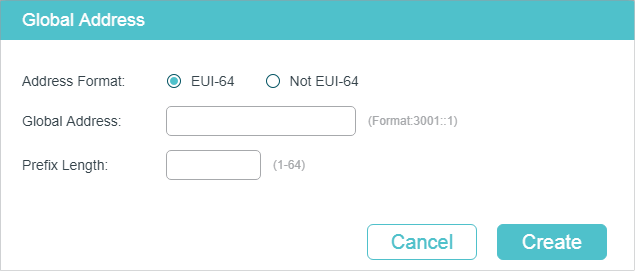
In the Global Address Config section, click to manually assign an IPv6 global address to the interface.
|
Address Format |
Select the global address format according to your needs. EUI-64: Indicates that you only need to specify an address prefix, then the system will create a global address automatically. Not EUI-64: Indicates that you have to specify an intact global address. |
|
Global Address |
When EUI-64 is selected, please input the address prefix here, otherwise, please input an intact IPv6 address here. |
|
Prefix Length |
Configure the prefix length of the global address. |
3)View the global address entry in the Global Address Config.
|
Global Address |
View or modify the global address. |
|
Prefix Length |
View or modify the prefix length of the global address. |
|
Type |
Displays the configuration mode of the global address. Manual: Indicates that the corresponding address is configured manually. Auto: Indicates that the corresponding address is created automatically using the RA message or obtained from the DHCPv6 Server. |
|
Preferred Lifetime |
Displays the preferred lifetime of the global address. Preferred lifetime is the length of time that a valid IPv6 address is preferred. When the preferred time expires, the address becomes deprecated but still can be used, and you need to switch to another address. |
|
Valid Lifetime |
Displays the valid lifetime of the global address. Valid lifetime is the length of time that an IPv6 address is in the valid state. When the valid lifetime expires, the address become invalid and can be no longer usable. |
|
Status |
Displays the status of the link-local address. An IPv6 address cannot be used before pass the DAD (Duplicate Address Detection), which is used to detect the address conflicts. In the DAD process, the IPv6 address may in three different status: Normal: Indicates that the global address passes the DAD and can be normally used. Try: Indicates that the global address is in the progress of DAD and cannot be used right now. Repeat: Indicates that the global address is duplicated, this address is already used by another node. This address cannot be used by the interface. |
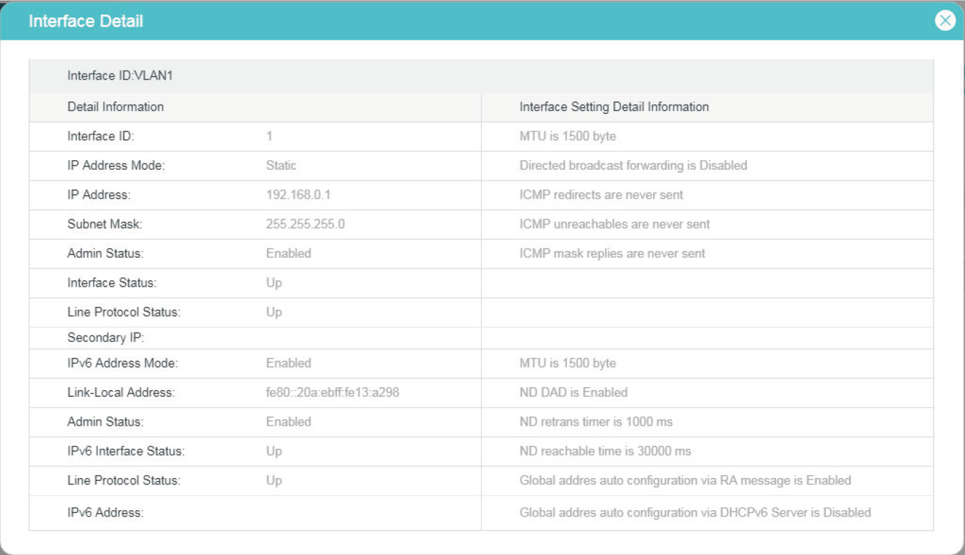
2.1.4Viewing Detail Information of the Interface
In Figure 2-1, you can view the corresponding interface entry you have created in the Interface Config section. On the corresponding interface entry, click Detail to load the following page and view the detail information of the interface.
Figure 2-4 Viewing the detail information of the interface
2.2Using the CLI
2.2.1Creating a Layer 3 Interface
Follow these steps to create a Layer 3 interface. You can create a VLAN interface, a loopback interface, a routed port or a port-channel interface according to your needs.
|
Step 1 |
configure Enter global configuration mode. |
|
Step 2 |
Create a VLAN interface: interface vlan vlan-id vlan-id: Specify an IEEE 802.1Q VLAN ID that already exists, ranging from 1 to 4094. Create a loopback interface: interface loopback { id } id: Specify the ID of the loopback interface, ranging from 1 to 64. Create a routed port: interface { fastEthernet port | range fastEthernet port-list | gigabitEthernet port | range gigabitEthernet port-list | ten-gigabitEthernet port | range ten-gigabitEthernet port-list } Enter interface configuration mode. port: Specify the Ethernet port number, for example 1/0/1. port-list: Specify the list of Ethernet ports, for example 1/0/1-3, 1/0/5. no switchport Switch the Layer 2 port into the Layer 3 routed port. Create a port-channel interface: interface { port-cahnnel port-channel | range port-channel port-channel-list } Enter interface configuration mode. port-channel: Specify the port channel, the valid value ranges from 1 to 14. port-channel-list: Specify the list of the port-channel interface, for example 1-3, 5. no switchport Switch the port channel to a Layer 3 port channel interface. |
|
Step 3 |
description string Specify a description for the Layer 3 interface. string: The description of the Layer 3 interface, ranging from 1 to 32 characters. |
|
Step 4 |
end Return to privileged EXEC mode. |
|
Step 5 |
copy running-config startup-config Save the settings in the configuration file. |
The following example shows how to create a VLAN interface with a description of VLAN-2.
Switch#configure
Switch(config)#interface vlan 2
Switch(config-if)#description VLAN-2
Switch(config-if)#end
Switch#copy running-config startup-config
2.2.2Configuring IPv4 Parameters of the Interface
Follow these steps to configure the IPv4 parameters of the interface.
|
Step 1 |
configure Enter global configuration mode. |
|
Step 2 |
interface { interface-type } { interface-id} Enter Layer 3 interface configuration mode. interface-type: Type of the Layer 3 interface, including fastEthernet, gigabitEthernet, interface-id: The interface ID. |
|
Step 3 |
Automatically assign an IP Address for the interface via DHCP or BOOTP: ip address-alloc { dhcp | bootp } Specify the IP Address assignment mode of the interface. dhcp: Specify the Layer 3 interface to obtain an IPv4 address from the DHCP Server. bootp: Specify the Layer 3 interface to obtain an IPv4 address from the BOOTP Server. Manually assign an IP Address for the interface: ip address { ip-addr } { mask } [ secondary ] Configure the IP address and subnet mask for the specified interface manually. ip-addr: Specify thse IP address of the Layer 3 interface. mask: Specify the subnet mask of the Layer 3 interface. secondary: Specify the interface’s secondary IP address which allows you to have two logical subnets. If this parameter is omitted here, the configured IP address is the interface’s primary address. |
|
Step 4 |
show ip interface brief Verify the summary information of the Layer 3 interfaces. |
|
Step 5 |
end Return to privileged EXEC mode. |
|
Step 6 |
copy running-config startup-config Save the settings in the configuration file. |
The following example shows how to configure the IPv4 parameters of a routed port, including setting a static IP address for the port and enabling the Layer 3 capabilities:
Switch#configure
Switch(config)#interface gigabitEthernet 1/0/1
Switch(config-if)#no switchport
Switch(config-if)#ip address 192.168.0.100 255.255.255.0
Switch(config-if)#show ip interface brief
Interface IP-Address Method Status Protocol Shutdown
--------- ---------- ------ ------ -------- --------
Gi1/0/1 192.168.0.100/24 Static Up Up no
Switch(config-if)#end
Switch#copy running-config startup-config
2.2.3Configuring IPv6 Parameters of the Interface
Follow these steps to configure the IPv6 parameters of the interface.
|
Step 1 |
configure Enter global configuration mode. |
|
Step 2 |
interface { interface-type } { interface-id } Enter Layer 3 interface configuration mode. interface-type: Type of the Layer 3 interface, including fastEthernet, gigabitEthernet, interface-id: The interface ID. |
|
Step 3 |
ipv6 enable Enable the IPv6 feature on the specified Layer 3 interface. By default, it is enabled on VLAN interface 1. IPv6 function can only be enabled on one Layer 3 interface at a time. |
|
Step 4 |
Configure the IPv6 link-local address for the specified interface: Manually configure the ipv6 link-local address for the specified interface: ipv6 address ipv6-addr link-local ipv6-addr: Specify the link-local address of the interface. It should be a standardized IPv6 address with the prefix fe80::/10, otherwise this command will be invalid. Automatically configure the ipv6 link-local address for the specified interface: ipv6 address autoconfig |
|
Step 5 |
Configure the IPv6 global address for the specified interface: Automatically configure the interface’s global IPv6 address via RA message: ipv6 address ra Configure the interface’s global IPv6 address according to the address prefix and other configuration parameters from its received RA (Router Advertisement) message. Automatically configure the interface’s global IPv6 address via DHCPv6 server: ipv6 address dhcp Enable the DHCPv6 Client function. When this function is enabled, the Layer 3 interface will try to obtain the IPv6 address from DHCPv6 server. Manually configure the interface’s global IPv6 address: ipv6 address ipv6-addr ipv6-addr: The Global IPv6 address with network prefix, for example 3ffe::1/64. ipv6 address ipv6-addr eui-64 Specify a global IPv6 address with an extended unique identifier (EUI) in the low-order 64 bits of the IPv6 address. Specify only the network prefix; the last 64 bits are automatically computed from the switch MAC address. This enables IPv6 processing on the interface. |
|
Step 6 |
show ipv6 interface Verify the configured ipv6 information of the interface. |
|
Step 7 |
end Return to privileged EXEC mode. |
|
Step 8 |
copy running-config startup-config Save the settings in the configuration file. |
The following example shows how to enable the IPv6 function and configure the IPv6 parameters of a VLAN interface:
Switch#configure
Switch(config)#interface vlan 2
Switch(config-if)#ipv6 enable
Switch(config-if)#ipv6 address autoconfig
Switch(config-if)#ipv6 address dhcp
Switch(config-if)#show ipv6 interface
Vlan2 is up, line protocol is up
IPv6 is enable, Link-Local Address: fe80::20a:ebff:fe13:237b[NOR]
Global Address RA: Disable
Global Address DHCPv6: Enable
Global unicast address(es): ff02::1:ff13:237b
Joined group address(es): ff02::1
ICMP error messages limited to one every 1000 milliseconds
ICMP redirects are enable
MTU is 1500 bytes
ND DAD is enable, number of DAD attempts: 1
ND retrans timer is 1000 milliseconds
ND reachable time is 30000 milliseconds
Switch(config-if)#end
Switch#copy running-config startup-config
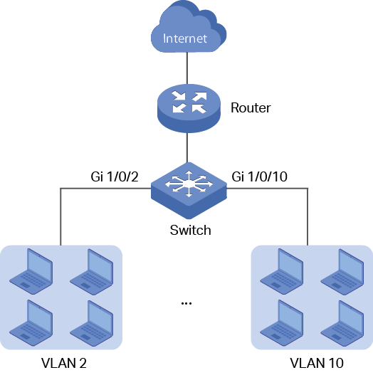
3.1Network Requirement
The administrator need to allow the hosts in VLANs can access the internet. The topology is shown as below.
Figure 3-1 Network Topology
3.2Configuration Scheme
For the hosts in VLANs are seperated at layer 2. To make it possible for these host to access the internet, we need to configure a VLAN interface on the switch for each VLAN. The VLAN interface can be considered as the default gateway for the hosts in the VLAN. All the requests to internet are sent to the VLAN interface first, then the VLAN interface will forward the packets to the internet according to the routing table.
Demonstrated with T2600G-28TS, this chapter provides configuration procedures in two ways: using the GUI and using the CLI.
3.3Using the GUI
For the configurations for all the VLANs are similiar, here we only take the configuration of VLAN interface for VLAN 2 as an example.
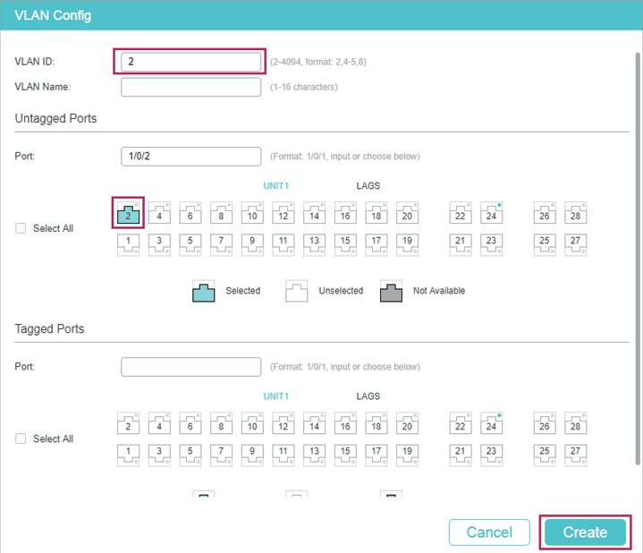
1)Go to L2 FEATURES > VLAN > 802.1Q VLAN to create VLAN 2. Add port 1/0/2 to VLAN 2 with its egress rule as Untagged.
Figure 3-2 Create VLAN 2
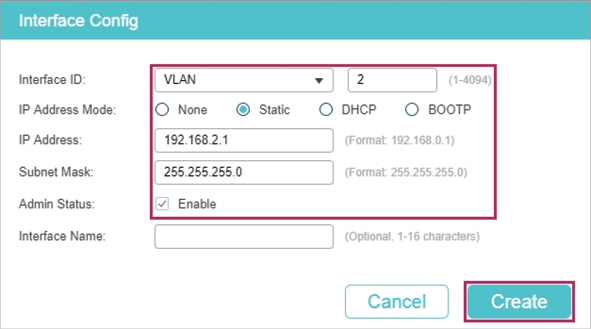
2)Go to L3 FEATURES > Interface to enable IPv4 routing (enabled by default), then click to create VLAN interface 2. Here we choose the IP address mode as Static and manually assign an IP address 192.168.2.1 to the interface.
Figure 3-3 Create VLAN Interface 2
3)Click  to save the settings.
3.3.1Using the CLI
1)Create VLAN 2 and add port 1/0/2 to VLAN 2 with its egress rule as Untagged.
Switch#configure
Switch(config)#vlan 2
Switch(config-vlan)#exit
Switch(config)#interface gigabitEthernet 1/0/2
Switch(config-if)#switchport general allowed vlan 2 untagged
Switch(config-if)#exit
2)Create VLAN interface 2 for VLAN 2. Configure the IP address of VLAN interface 2 as 192.168.2.1.
Switch(config)#interface vlan 2
Switch(config-if)#ip address 192.168.2.1 255.255.255.0
Switch(config-if)#end
Switch#copy running-config startup-config
Verify the VLAN Interface Configurations
Verify the configurations of VLAN interface 2.
Switch#show interface vlan 2
VLAN2 is down, line protocol is down
Hardware is CPU Interface, address is 00:0a:eb:13:a2:98
ip is 192.168.2.1/24
Default settings of interface are listed in the following tables.
Table 4-1Default Settings of Routing Config
|
Parameter |
Default Setting |
|
IPv4 Routing |
Enable |
|
IPv6 Routing |
Disable |
Table 4-2Configuring the IPv4 Parameters of the Interface
|
Parameter |
Default Setting |
|
Interface ID |
VLAN |
|
IP Address Mode |
None |
|
Admin Status |
Enable |
Table 4-3Configuring the IPv6 Parameters of the Interface
|
Parameter |
Default Setting |
|
Admin Status |
Enable |
|
IPv6 Enable |
Enable |
|
Link-local Address Mode |
Auto |
|
Enable global address auto configuration via RA message |
Enable |
|
Enable global address auto configuration via DHCPv6 Server |
Disable |