Configuring L2PT
CHAPTERS
4. Appendix: Default Parameters
|
|
This guide applies to: T2500G-10TS v2 or above, T2600G-18TS v2 or above, T2600G-28TS v3 or above, T2600G-28MPS v3 or above, T2600G-28SQ v1 or above, T2600G-52TS v3 or above. |

L2PT (Layer 2 Protocol Tunneling) is a feature for service providers to transparently transmit Layer 2 protocol data units (PDUs) between customer networks at different locations through a public ISP network. Some terminology that is used in this section is defined as follows:
Edge Switch: The switch that is connected to the customer network and placed on the boundary of the ISP network.
UNI: User Network Interface, a port configured on the edge switch which is connected to the customer network.
NNI: Network Network Interface, a port configured on the edge switch which is connected to the ISP network.
As shown in Figure 1-1, a customer has two local networks which are connected through the ISP network. When the two customer networks run the same Layer 2 protocol, the Layer 2 PDUs between them must be transmitted through the ISP network to perform Layer 2 protocol calculation (for example, calculating a spanning tree). Generally, the PDUs of the same Layer 2 protocol use the same destination MAC address. Therefore, when a Layer 2 PDU from a customer network reaches a edge switch in the ISP network, the switch cannot identify whether the PDU comes from a customer network or the ISP network and then the PDU will be discarded. As a result, the Layer 2 PDUs cannot be transmitted through the ISP network to the other side.
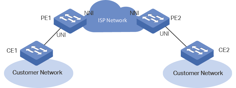
To resolve this problem, the ISP network should transparently transmit the Layer 2 PDUs between the two customer networks. In this case, L2PT feature can be configured on the edge switches (PE1 and PE2) to allow the Layer 2 PDUs to be tunneled through the network.
The following describes the PDUs transmission procedure through the ISP network from one customer network to the other side:
1)Upon receiving a Layer 2 PDU from CE1 via the UNI port, PE1 replaces the destination MAC address of the PDU with a special multicast MAC address (01:00:0c:cd:cd: d0) and then sends the PDU to the ISP network via the NNI port.
2)The ISP network identifies the PDU and directly forwards it to the other end.
3)PE2 receives the PDU via its NNI port and restores the destination MAC address of the PDU to its original destination MAC address.
With L2PT feature configured accordingly, the switch can transparently transmit the PDUs of the following Layer 2 protocols: STP (Spanning Tree Protocol), GVRP (GARP VLAN Registration Protocol), LACP (Link Aggregation Control Protocol), CDP (Cisco Discovery Protocol), VTP (VLAN Trunking Protocol), PAgP (Port Aggregation Protocol), UDLD (UniDirectional Link Detection) and PVST+(Per VLAN Spanning Tree Plus).
2.1Using the GUI
Choose the menu L2 FEATURES > L2PT to load the following page.
Figure 2-1 Configuring L2PT
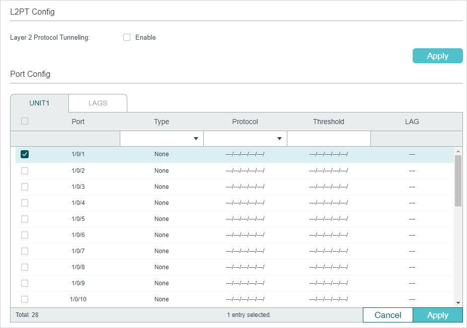
Follow these steps to configure L2PT:
1)In the L2PT Config section, enable L2PT globally and click Apply.
2)In the Port Config section, configure the port that is connected to the customer network as a UNI port and specify your desired protocols on the port. In addition, you can also set the threshold for packets-per-second to be processed on the UNI port.
|
Port |
Displays the port number. |
|
Type |
Select UNI as the port type for the selected port. Usually, the UNI port is connected to the customer network. The default setting is None which indicates that L2PT is disabled on this port. |
|
Protocol |
Specify the Layer 2 protocol types of the packets that can be transparently transmitted on the selected port: STP: Enable protocol tunneling for the STP packets. GVRP: Enable protocol tunneling for the GVRP packets. 01000CCCCCCC: Enable protocol tunneling for the packets with their destination MAC address as 01000CCCCCCC, which includes CDP, VTP, PAgP and UDLD. 01000CCCCCCD: Enable protocol tunneling for the PVST+ packets with the destination MAC address as 01000CCCCCCD. LACP: Enable protocol tunneling for the LACP packets. All: All the above Layer 2 protocols are supported for tunneling. |
|
Threshold |
Specify the maximum number of packets to be processed for the specified protocol on the port in one second. When the threshold is exceeded, the port drops the specified Layer 2 protocol packets. This value ranges from 1 to 1000 (packets per second). 0 indicates that the threshold feature is disabled. |
|
LAG |
Displays the LAG that the port is in. |
3)In the Port Config section, configure the port that is connected to the ISP network as an NNI port. Note that the protocols and threshold cannot be configured on the NNI port.
|
Port |
Displays the port number. |
|
Type |
Select NNI as the port type for the selected port. Usually, NNI port is connected to the ISP network. The default setting is None, which indicates that L2PT is disabled on this port. |
|
LAG |
Displays the LAG that the port is in. |
4)Click Apply.
|
|
Note: The member port of an LAG (Link Aggregation Group) follows the configuration of the LAG and not its own. The configurations of the port can take effect only after it leaves the LAG. |

2.2Using the CLI
Follow these steps to configure L2PT feature.
|
Step 1 |
configure Enter global configuration mode. |
|
Step 2 |
l2protocol-tunnel Enable the L2PT feature globally. |
|
Step 3 |
interface { fastEthernet port | range fastEthernet port-list | gigabitEthernet port | range gigabitEthernet port-list | ten-gigabitEthernet port | range ten-gigabitEthernet port-list | port-channel port-channel-id | range port-channel port-channel-id-list } Enter interface configuration mode. |
|
Step 4 |
l2protocol-tunnel type uni { 01000ccccccc | 01000ccccccd | gvrp | stp | lacp | all } [ threshold threshold ] Configure the port as a UNI port, specify the Layer 2 protocol types of the packets that can be transparently transmitted on the port, and set the threshold for packets-per-second accepted for encapsulation on the UNI port. 01000ccccccc: Enable protocol tunneling for the packets with their destination MAC address as 01000CCCCCCC, which includes CDP, VTP, PAgP and UDLD. 01000ccccccd: Enable protocol tunneling for the PVST+ packets with the destination MAC address as 01000CCCCCCD. gvrp: Enable protocol tunneling for the GVRP packets. stp: Enable protocol tunneling for the STP packets. lacp: Enable protocol tunneling for the LACP packets. all: All the above Layer 2 protocols are supported for tunneling. threshold: Set a threshold which determines the maximum number of packets to be processed for the specified protocol on the port in one second. When the threshold is exceeded, the port drops the specified Layer 2 protocol packets. The valid values are from 1 to 1000 (packets/second). 0 indicates that the threshold feature is disabled. |
|
Step 5 |
exit Return to global configuration mode. |
|
Step 6 |
interface { fastEthernet port | range fastEthernet port-list | gigabitEthernet port | range gigabitEthernet port-list | ten-gigabitEthernet port | range ten-gigabitEthernet port-list | port-channel port-channel-id | range port-channel port-channel-id-list } Enter interface configuration mode. |
|
Step 7 |
l2protocol-tunnel type nni Configure the port as an NNI port. |
|
Step 8 |
show l2protocol-tunnel global Verify the global L2PT configuration. |
|
Step 9 |
show l2protocol-tunnel interface [ fastEthernet port | gigabitEthernet port | ten-gigabitEthernet port | port-channel port-channel-id ] Verify the L2PT configuration of the port or LAG. |
|
Step 10 |
end Return to privileged EXEC mode. |
|
Step 11 |
copy running-config startup-config Save the settings in the configuration file. |
|
|
Note: The member port of an LAG (Link Aggregation Group) follows the configuration of the LAG and not its own. The configurations of the port can take effect only after it leaves the LAG. |

This example shows how to enable L2PT globally:
Switch#configure
Switch(config)#l2protocol-tunnel
Switch(config)#show l2protocol-tunnel global
l2protocol-tunnel State: Enable
Switch(config)#end
Switch#copy running-config startup-config
This example shows how to configure port 1/0/1 as a UNI port for the Layer 2 protocol GVRP and set the threshold as 1000:
Switch#configure
Switch(config)#interface gigabitEthernet 1/0/1
Switch(config-if)#l2protocol-tunnel type uni gvrp threshold 1000
Switch(config-if)#show l2protocol-tunnel interface gigabitEthernet 1/0/1
Interface Type Protocol Threshold LAG
--------- ---- -------- --------- ----
Gi1/0/1 uni gvrp,--,--,--,-- 1000,--,--,--,-- N/A
Switch(config-if)#end
Switch#copy running-config startup-config
This example shows how to configure port 1/0/5 as an NNI port.
Switch#configure
Switch(config)#interface gigabitEthernet 1/0/5
Switch(config-if)#l2protocol-tunnel type nni
Switch(config-if)#show l2protocol-tunnel interface gigabitEthernet 1/0/5
Interface Type Protocol Threshold LAG
--------- ---- -------- --------- ----
Gi1/0/5 nni --,--,--,--,-- --,--,--,--,-- N/A
Switch(config-if)#end
Switch#copy running-config startup-config
3.1Network Requirements
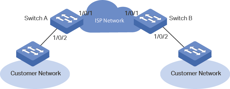
As shown below, the two branches of a company are connected through the ISP network, and they want to achieve spanning tree calculation by exchanging Layer 2 STP packets with each other. To meet this requirement, the ISP network needs to transparently transmit the STP packets between the two customer networks.
Figure 3-1 Network Topology
3.2Configuration Scheme
The service provider can configure L2PT on the two edge switches (Switch A and Switch B). With the L2PT feature, the STP packets can be encapsulated as normal data packets and sent to the other side without being processed by the devices in the ISP network.
The overview of configuration is as follows:
1)Enable the L2PT feature globally.
2)Specify port 1/0/1 which is connected to the ISP network as an NNI port.
3)Specify port 1/0/2 which is connected to the customer network as a UNI port for the STP. In addition, configure the threshold as 1000 to limit the number of packets to be processed on the port in one second.
Demonstrated with T2600G-28TS, the following sections provide configuration procedure in two ways: using the GUI and using the CLI.
3.3Using the GUI
The configurations of Switch A and Switch B are similar. The following introductions take Switch A as an example.
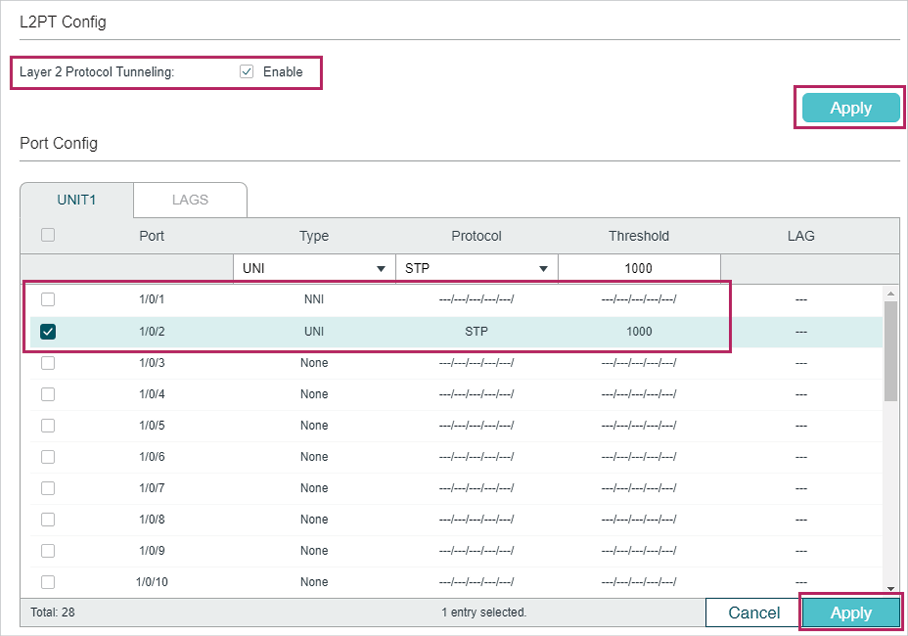
1)Choose the menu L2 FEATURES > L2PT to load the following page. Enable the L2PT feature globally and click Apply.
2)Specify port 1/0/1 as an NNI port and click Apply. Specify port 1/0/2 as a UNI port for the STP and set the threshold as 1000. Then click Apply. The configuration result is as follows:
Figure 3-2 Global Config
3)Click  to save the settings.
3.4Using the CLI
The configurations of Switch A and Switch B are similar. The following introductions take Switch A as an example.
Switch_A#configure
Switch_A(config)#l2protocol-tunnel
Switch_A(config)#interface gigabitEthernet 1/0/1
Switch_A(config-if)#l2protocol-tunnel type nni
Switch_A(config-if)#exit
Switch_A(config)#interface gigabitEthernet 1/0/2
Switch_A(config-if)#l2protocol-tunnel type uni stp 1000
Switch_A(config-if)#end
Switch_A#copy running-config startup-config
Verify the Configuration
Verify the global configuration:
Switch_A#show l2protocol-tunnel global
l2protocol-tunnel State: Enable
Verify the configuration on port 1/0/1:
Switch_A#show l2protocol-tunnel interface gigabitEthernet 1/0/1
Interface Type Protocol Threshold LAG
--------- ---- -------- --------- ----
Gi1/0/1 nni --,--,--,--,-- --,--,--,--,-- N/A
Verify the configuration on port 1/0/2:
Switch_A#show l2protocol-tunnel interface gigabitEthernet 1/0/2
Interface Type Protocol Threshold LAG
--------- ---- -------- --------- ----
Gi1/0/2 uni stp,--,--,--,-- 1000,--,--,--,-- N/A
Default settings of L2PT are listed in the following table.
Table 4-1Default Settings of L2PT
|
Parameter |
Default Setting |
|
L2PT Config |
|
|
Layer 2 Protocol Tunneling |
Disable |
|
Port Config |
|
|
Type |
None |
|
Protocol |
None |
|
Threshold |
None |