Configuring GVRP
CHAPTERS
4. Appendix: Default Parameters
|
|
This guide applies to: T1500G-8T v2 or above, T1500G-10PS v2 or above, T1500G-10MPS v2 or above, T1500-28PCT v3 or above, T1600G-18TS v2 or above, T1600G-28TS v3 or above, T1600G-28PS v3 or above, T1600G-52TS v3 or above, T1600G-52PS v3 or above, T1700X-16TS v3 or above, T2500G-10TS v2 or above, T2600G-18TS v2 or above, T2600G-28TS v3 or above, T2600G-28MPS v3 or above, T2600G-28SQ v1 or above, T2600G-52TS v3 or above. |

GVRP (GARP VLAN Registration Protocol) is a GARP (Generic Attribute Registration Protocol) application that allows registration and deregistration of VLAN attribute values and dynamic VLAN creation.
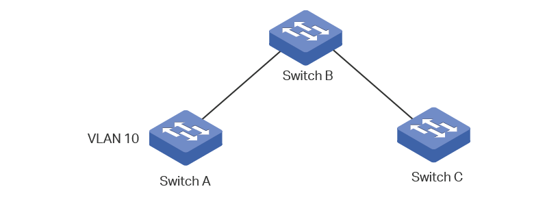
Without GVRP operating, configuring the same VLAN on a network would require manual configuration on each device. As shown in Figure 1-1, Switch A, B and C are connected through trunk ports. VLAN 10 is configured on Switch A, and VLAN 1 is configured on Switch B and Switch C. Switch C can receive messages sent from Switch A in VLAN 10 only when the network administrator has manually created VLAN 10 on Switch B and Switch C.
Figure 1-1 VLAN Topology
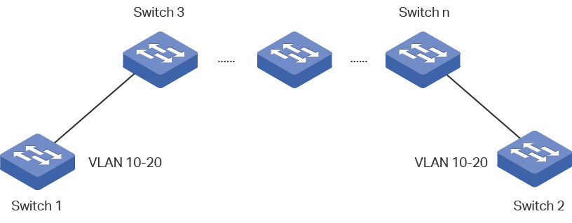
The configuration may seem easy in this situation. However, for a larger or more complex network, such manual configuration would be time-costing and fallible. GVRP can be used to implement dynamic VLAN configuration. With GVRP, the switch can exchange VLAN configuration information with the adjacent GVRP switches and dynamically create and manage the VLANs. This reduces VLAN configuration workload and ensures correct VLAN configuration.
Figure 1-2 GVRP Topology
To complete GVRP configuration, follow these steps:
1)Create a VLAN.
2)Enable GVRP globally.
3)Enable GVRP on each port and configure the corresponding parameters.
Configuration Guidelines
To dynamically create a VLAN on all ports in a network link, you must configure the same static VLAN on both ends of the link.
We call manually configured 802.1Q VLAN as static VLAN and VLAN created through GVRP as dynamic VLAN. Ports in a static VLAN can initiate the sending of GVRP registration message to other ports. And a port registers VLANs only when it receives GVRP messages. As the messages can only be sent from one GVRP participant to another, two-way registration is required to configure a VLAN on all ports in a link. To implement two-way registration, you need to manually configure the same static VLAN on both ends of the link.
As shown in the figure below, VLAN registration from Switch A to Switch C adds Port 2 to VLAN 2. And VLAN registration from Switch C to Switch A adds Port 3 to VLAN 2.
Figure 2-1
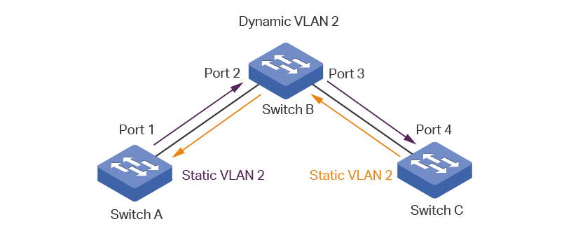
Similarly, if you want to delete a VLAN from the link, two-way deregistration is required. And you need to manually delete the static VALN on both ends of the link.
2.1Using the GUI
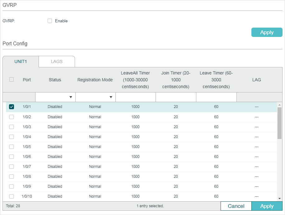
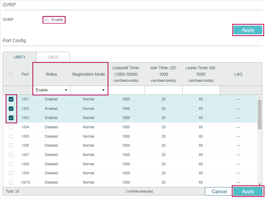
Choose the menu L2 FEATURES > VLAN > GVRP > GVRP Config to load the following page.
Figure 2-2 GVRP Config
Follow these steps to configure GVRP:
1)In the GVRP section, enable GVRP globally, then click Apply.
2)In the Port Config section, select one or more ports, set the status as Enable and configure the related parameters according to your needs.
|
Port |
Select the desired port for GVRP configuration. It is multi-optional. |
|
Status |
Enable or disable GVRP on the port. By default, it is disabled. |
|
Registration Mode |
Select the GVRP registration mode for the port. Normal: In this mode, the port can dynamically register and deregister VLANs, and transmit both dynamic and static VLAN registration information. Fixed: In this mode, the port is unable to dynamically register and deregister VLANs, and can transmit only the static VLAN registration information. Forbidden: In this mode, the port is unable to dynamically register and deregister VLANs, and can transmit only information of VLAN 1. |
|
LeaveAll Timer (centisecond) |
When a GARP participant is enabled, the LeaveAll timer will be started. When the LeaveAll timer expires, the GARP participant will send LeaveAll messages to request other GARP participants to re-register all its attributes. After that, the participant restarts the LeaveAll timer. The timer ranges from 1000 to 30000 centiseconds. The default value is 1000 centiseconds. |
|
Join Timer (centisecond) |
Join timer controls the sending of Join messages. A GVRP participant starts the Join timer after sending the first Join message. If the participant does not receive any response, it will send the second Join message when the Join timer expires to ensures that the Join message can be sent to other participants. The timer ranges from 20 to 1000 centiseconds. The default value is 20 centiseconds. |
|
Leave Timer (centisecond) |
The Leave timer controls attribute deregistration. A participant will send a Leave message if it wants other participants to deregister some of its attributes. The participant receiving the message starts the Leave timer. If the participant does not receive any Join message of the corresponding attribute before the Leave timer expires, the participant deregisters the attribute. The timer ranges from 60 to 3000 centiseconds. The default value is 60 centiseconds. |
|
LAG |
Displays the LAG the port is in. |
3)Click Apply.
|
|
Note: The member port of an LAG follows the configuration of the LAG and not its own. The configurations of the port can take effect only after it leaves the LAG. The egress rule of the ports dynamically added to the VLAN is tagged. The egress rule of the fixed port should be tagged. When setting the timer values, make sure the values are within the required range. The configuration value for LeaveAll should be greater than or equal to ten times the Leave value. The value for Leave should be greater than or equal to two times the Join value. |

2.2Using the CLI
|
Step 1 |
configure Enter global configuration mode. |
|
Step 2 |
gvrp Enable GVRP globally. |
|
Step 3 |
interface {fastEthernet port | range fastEthernet port-list | gigabitEthernet port | range gigabitEthernet port-list | ten-gigabitEthernet port | range ten-gigabitEthernet port-list | port-channel port-channel-id | range port-channel port-channel-list} Enter interface configuration mode. |
|
Step 4 |
gvrp Enable GVRP on the port. |
|
Step 5 |
gvrp registration { normal | fixed | forbidden } Configure the GVRP registration mode for the port. By default, it is normal. normal: In this mode, the port can dynamically register and deregister VLANs, and transmit both dynamic and static VLAN registration information. fixed: n this mode, the port is unable to dynamically register and deregister VLANs, and can transmit only the static VLAN registration information. forbidden: In this mode, the port is unable to dynamically register and deregister VLANs, and can transmit only information of VLAN 1. |
|
Step 6 |
gvrp timer { leaveall | join | leave } value Set the GARP timers according to your needs. leaveall: When a GARP participant is enabled, the LeaveAll timer will be started. When the LeaveAll timer expires, the GARP participant will send LeaveAll messages to request other GARP participants to re-register all its attributes. After that, the participant restarts the LeaveAll timer. join: Join timer controls the sending of Join messages. A GVRP participant starts the Join timer after sending the first Join message. If the participant does not receive any response, it will send the second Join message when the Join timer expires to ensures that the Join message can be sent to other participants. leave: The Leave timer controls attribute deregistration. A participant will send a Leave message if it wants other participants to deregister some of its attributes. The participant receiving the message starts the Leave timer. If the participant does not receive any Join message of the corresponding attribute before the Leave timer expires, the participant deregisters the attribute. value: Set a value for the timer. For LeaveAll timer, the valid values are from 1000 to 30000 centiseconds and the default value is 1000 centiseconds. For Join timer, the valid values are from 20 to 1000 centiseconds and the default value is 20 centiseconds. For Leave timer, the valid values are from 60 to 3000 centiseconds and the default value is 60 centiseconds. |
|
Step 7 |
show gvrp global Verify the global configurations of GVRP. |
|
Step 8 |
show gvrp interface [ fastEthernet port | gigabitEthernet port | ten-gigabitEthernet port | port-channel port-channel-id ] Verify the GVRP configuration of the specified port or LAG. |
|
Step 9 |
end Return to privileged EXEC mode. |
|
Step 10 |
copy running-config startup-config Save the settings in the configuration file. |
|
|
Note: The member port of an LAG follows the configuration of the LAG and not its own. The configurations of the port can take effect only after it leaves the LAG. The egress rule of the ports dynamically added to the VLAN is tagged. The egress rule of the fixed port should be tagged. When setting the timer values, make sure the values are within the required range. The value for LeaveAll should be greater than or equal to ten times the Leave value. The value for Leave should be greater than or equal to two times the Join value. |

The following example shows how to enable GVRP globally and on port 1/0/1, configure the GVRP registration mode as fixed and keep the values of timers as default:
Switch#configure
Switch(config)#gvrp
Switch(config)#interface gigabitEthernet 1/0/1
Switch(config-if)#gvrp
Switch(config-if)#gvrp registration fixed
Switch(config-if)#show gvrp global
GVRP Global Status
------------------
Enabled
Switch(config-if)# show gvrp interface gigabitEthernet 1/0/1
Port Status Reg-Mode LeaveAll JoinIn Leave LAG
---- ------ -------- -------- ------ ----- ---
Gi1/0/1 Enabled Fixed 1000 20 60 N/A
Switch(config-if)#end
Switch#copy running-config startup-config
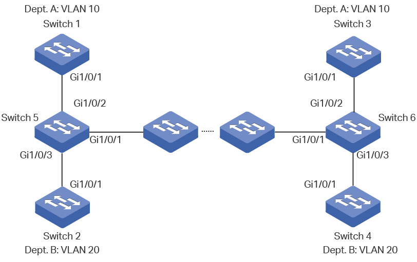
3.1Network Requirements
Department A and Department B of a company are connected using switches. Offices of one department are distributed on different floors. As shown in Figure 3-1, the network topology is complicated. Configuration of the same VLAN on different switches is required so that computers in the same department can communicate with each other.
Figure 3-1 Network Topology
3.2Configuration Scheme
To reduce manual configuration and maintenance workload, GVRP can be enabled to implement dynamic VLAN registration and update on the switches.
When configuring GVRP, please note the following:
The two departments are in separate VLANs. To make sure the switches only dynamically create VLAN of their own department, you need to set the registration mode for ports on Switch 1 to Switch 4 as Fixed to prevents dynamic registration and deregistration of VLANs and allow the port to transmit only the static VLAN registration information.
To configure dynamic VLAN creation on other switches, set the registration mode of the corresponding ports as Normal to allow dynamic registration and deregistration of VLANs.
Demonstrated with T2600G-28TS, the following sections provide configuration procedure in two ways: using the GUI and using the CLI.
3.3Using the GUI
GVRP configuration for Switch 3 is the same as Switch 1, and Switch 4 the same as Switch 2. Other switches share similar configurations.
The following configuration procedures take Switch 1, Switch 2 and Switch 5 as example.
Configurations for Switch 1
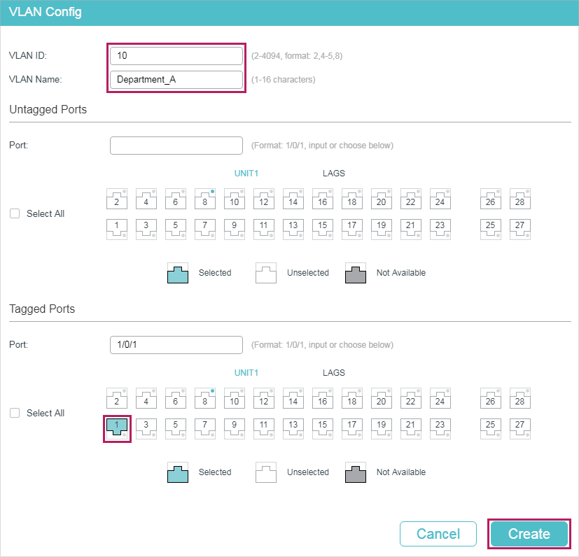
1)Choose the menu L2 FEATURES > VLAN > 802.1Q VLAN > VLAN Config and click  to load the following page. Create VLAN 10 and add tagged port 1/0/1 to it. Click Create.
Figure 3-2 Create VLAN 10
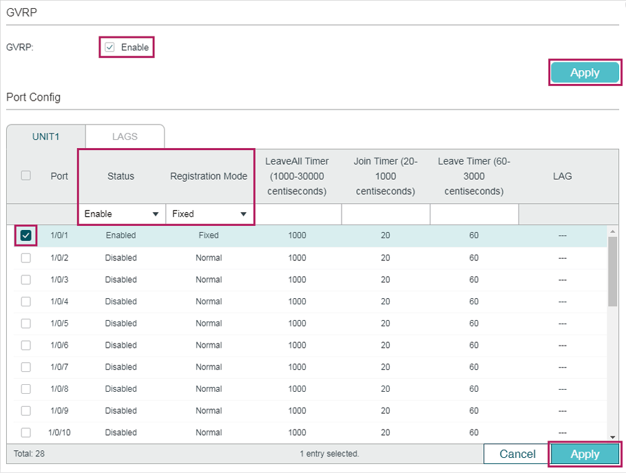
2)Choose the menu L2 FEATURES > VLAN > GVRP to load the following page. Enable GVRP globally, then click Apply. Select port 1/0/1, set Status as Enable, and set Registration Mode as Fixed. Keep the values of the timers as default. Click Apply.
Figure 3-3 GVRP Configuration
3)Click  to save the settings.
Configurations for Switch 2
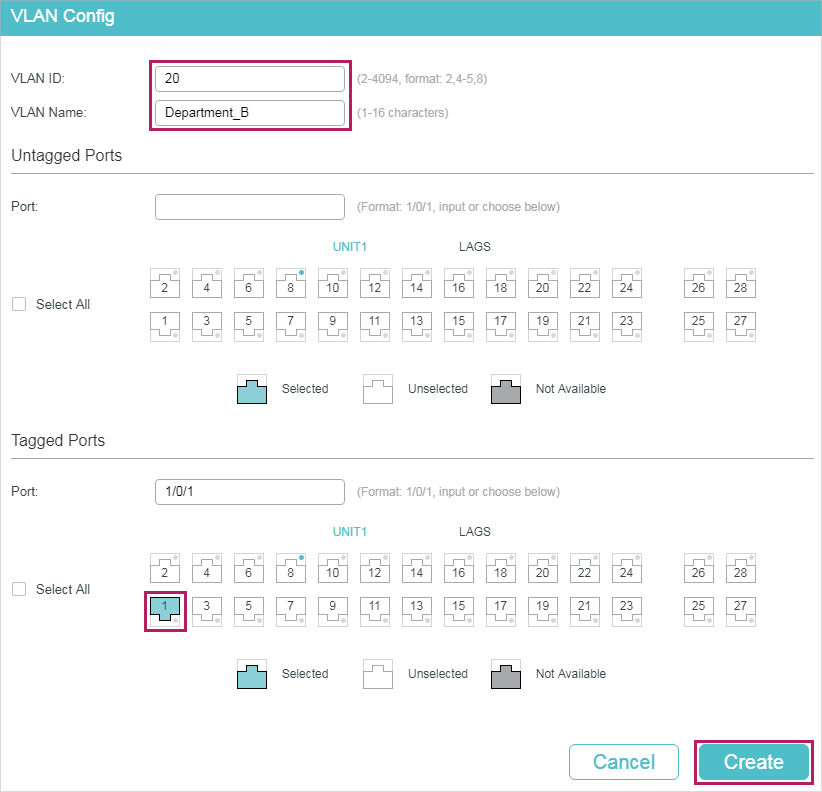
4)Choose the menu L2 FEATURES > VLAN > 802.1Q VLAN > VLAN Config and click to load the following page. Create VLAN 20 and add tagged port 1/0/1 to it. Click Create.
Figure 3-4 Create VLAN 20
5)Choose the menu L2 FEATURES > VLAN > GVRP to load the following page. Enable GVRP globally, then click Apply. Select port 1/0/1, set Status as Enable, and set Registration Mode as Fixed. Keep the values of the timers as default. Click Apply.
Figure 3-5 GVRP Configuration
6)Click to save the settings.
Configurations for Switch 5
1)Choose the menu L2 FEATURES > VLAN > GVRP to load the following page. Enable GVRP globally, then click Apply. Select ports 1/0/1-3, set Status as Enable, and keep the Registration Mode and the values of the timers as default. Click Apply.
Figure 3-6 GVRP Configuration
2)Click to save the settings.
3.4Using the CLI
GVRP configuration for Switch 3 is the same as Switch 1, and Switch 4 the same as Switch 2. Other switches share similar configurations.
The following configuration procedures take Switch 1, Switch 2 and Switch 5 as example.
Configurations for Switch 1
1)Enable GVRP globally.
Switch_1#configure
Switch_1(config)#gvrp
2)Create VLAN 10.
Switch_1(config)#vlan 10
Switch_1(config-vlan)#name Department A
Switch_1(config-vlan)#exit
3)Add tagged port 1/0/1 to VLAN 10. Enable GVRP on port and set the registration mode as Fixed.
Switch_1(config)#interface gigabitEthernet 1/0/1
Switch_1(config-if)#switchport general allowed vlan 10 tagged
Switch_1(config-if)#gvrp
Switch_1(config-if)#gvrp registration fixed
Switch_1(config-if)#end
Switch_1#copy running-config startup-config
Configurations for Switch 2
1)Enable GVRP globally.
Switch_2#configure
Switch_2(config)#gvrp
2)Create VLAN 20.
Switch_2(config)#vlan 20
Switch_2(config-vlan)#name Department B
Switch_2(config-vlan)#exit
3)Add tagged port 1/0/1 to VLAN 20. Enable GVRP on the port and set the registration mode as Fixed.
Switch_2(config)#interface gigabitEthernet 1/0/1
Switch_2(config-if)#switchport general allowed vlan 20 tagged
Switch_2(config-if)#gvrp
Switch_2(config-if)#gvrp registration fixed
Switch_2(config-if)#end
Switch_2#copy running-config startup-config
Configurations for Switch 5
1)Enable GVRP globally.
Switch_5#configure
Switch_5(config)#gvrp
2)Enable GVRP on ports 1/0/1-3.
Switch_5(config)#interface range gigabitEthernet 1/0/1-3
Switch_5(config-if-range)#gvrp
Switch_5(config-if-range)#end
Switch_5#copy running-config startup-config
Verify the Configuration
Switch 1
Verify the global GVRP configuration:
Switch_1#show gvrp global
GVRP Global Status
------------------
Enabled
Verify GVRP configuration for port 1/0/1:
Switch_1#show gvrp interface
Port Status Reg-Mode LeaveAll JoinIn Leave LAG
---- ------ -------- ------- ------ ----- ---
Gi1/0/1 Enabled Fixed 1000 20 60 N/A
Gi1/0/2 Disabled Normal 1000 20 60 N/A
......
Switch 2
Verify the global GVRP configuration:
Switch_2#show gvrp global
GVRP Global Status
------------------
Enabled
Verify GVRP configuration for port 1/0/1:
Switch_2#show gvrp interface
Port Status Reg-Mode LeaveAll JoinIn Leave LAG
---- ------ -------- ------- ------ ----- ---
Gi1/0/1 Enabled Fixed 1000 20 60 N/A
Gi1/0/2 Disabled Normal 1000 20 60 N/A
......
Switch 5
Verify global GVRP configuration:
GVRP Global Status
------------------
Enabled
Verify GVRP configuration for ports 1/0/1-3:
Switch_5#show gvrp interface
Port Status Reg-Mode LeaveAll JoinIn Leave LAG
---- ------ -------- ------- ------ ----- ---
Gi1/0/1 Enabled Normal 1000 20 60 N/A
Gi1/0/2 Enabled Normal 1000 20 60 N/A
Gi1/0/3 Enabled Normal 1000 20 60 N/A
Gi1/0/4 Disabled Normal 1000 20 60 N/A
......
Default settings of GVRP are listed in the following tables.
Table 4-1Default Settings of GVRP
|
Parameter |
Default Setting |
|
Global Config |
|
|
GVRP |
Disabled |
|
Port Config |
|
|
Status |
Disabled |
|
Registration Mode |
Normal |
|
LeaveAll Timer |
1000 centiseconds |
|
Join Yimer |
20 centiseconds |
|
Leave Timer |
60 centiseconds |