Configuring Firewall
CHAPTERS
|
|
This guide applies to: TL-R470T+ v6 or above, TL-R480T+ v9 or above, TL-R600VPN v4 or above, TL-ER5120 v3 or above, TL-ER6020 v2 or above, TL-ER6120 v3 or above |

1.1Overview
Firewall is used to enhance the network security. It can prevent external network threats from spreading to the internal network, protect the internal hosts from ARP attacks, and control the internal users’ access to the external network.
1.2Supported Features
The Firewall module supports four functions: Anti ARP Spoofing, Attack Defense, MAC Filtering and Access Control.
Anti ARP Spoofing
ARP (Address Resolution Protocol) is used to map IP addresses to the corresponding MAC addresses so that packets can be delivered to their destinations. However, since ARP is implemented with the premise that all the hosts and gateways are trusted, there are high security risks on real, complex networks. If attackers send ARP spoofing packets with false IP address-to-MAC address mapping entries, the device will update the ARP table based on the false ARP packets and record wrong mapping entries, which results in a breakdown of normal communication.
Anti ARP Spoofing can protect the network from ARP spoofing attacks. It works based on the IP-MAC Binding entries. These entries record the correct one-to-one relationships between IP addresses and MAC addresses. When receiving an ARP packet, the router checks whether it matches any of the IP-MAC Binding entries. If not, the router will ignore the ARP packets. In this way, the router maintains the correct ARP table.
In addition, the router provides the following two sub functions:
Permitting the packets matching the IP-MAC Binding entries only and discarding other packets.
Sending GARP packets to the hosts when it detects ARP attacks. The GARP packets can inform hosts of the correct ARP table, preventing their ARP tables from being falsified by ARP spoofing packets.
Attack Defense
Attacks on a network device can cause device or network paralysis. With the Attack Defense feature, the router can identify and discard various attack packets which are sent to the CPU, and limit the packet receiving rate. In this way, the router can protect itself and the connected network against malicious attacks.
The router provides two types of Attack Defense: Flood Defense and Packet Anomaly Defense. Flood Defense limits the receiving rate of the specific types of packets, and Packet Anomaly Defense discards the illegal packets directly.
MAC Filtering
MAC Filtering can flexibly control the access to the network of the specific hosts. You can simply add the MAC addresses of the hosts to the MAC Filtering List and specify the filtering rule for these hosts. Two rules are provided: allow the packets with the MAC addresses in the MAC Filtering List and deny other packets, or deny the packets with the MAC addresses in the MAC Filtering List and allow other packets.
Access Control
Access Control can filter the packets passing through the router based on the Access Control rules. An Access Control rule includes a filter policy and some conditions, such as service type, receiving interface and effective time. The router will apply the filter policy to the packets matching these conditions, and thus to limit network traffic, manage network access behaviors and more.
Access Control can prevent various network attacks, such as attacks on TCP (Transmission Control Protocol) and ICMP (Internet Control Message Protocol) packets, and can also manage network access behaviors, such as controlling access to the internet.
In Firewall module, you can configure the following features:
Anti ARP Spoofing
Attack Defense
MAC Filtering
Access Control
2.1Anti ARP Spoofing
To complete Anti ARP Spoofing configuration, there are two steps. First, add IP-MAC Binding entries to the IP-MAC Binding List. Then enable Anti ARP Spoofing for these entries.
|
|
Note: In case Anti ARP Spoofing causes access problems to the currently connected devices, we recommend that you add and verify the IP-MAC Binding entries first before enabling Anti ARP Spoofing. |

2.1.1Adding IP-MAC Binding Entries
You can add IP-MAC Binding entries in two ways: manually and via ARP scanning.
Adding IP-MAC Binding Entries Manually
You can manually bind the IP address, MAC address and interface together on the condition that you have got the related information of the hosts on the network.
Adding IP-MAC Binding Entries via ARP Scanning
With ARP Scanning, the router sends the ARP request packets with the specific IP field to the hosts. Upon receiving the ARP reply packet, the router can get the IP address, MAC address and connected interface of the host.
The following sections introduce these two methods in detail.
Adding IP-MAC Binding Entries Manually
Before adding entries manually, get the IP addresses and MAC addresses of the hosts on the network and make sure of their accuracy.
Choose the menu Firewall > Anti ARP Spoofing > IP-MAC Binding to load the following page.
Figure 2-1 IP-MAC Binding Page
Follow the steps below to add IP-MAC Binding entries manually. The entries will take effect on the LAN interface.
1)In the IP-MAC Binding List section, click Add to load the following page.
Figure 2-2 Add IP-MAC Binding Entries Manually
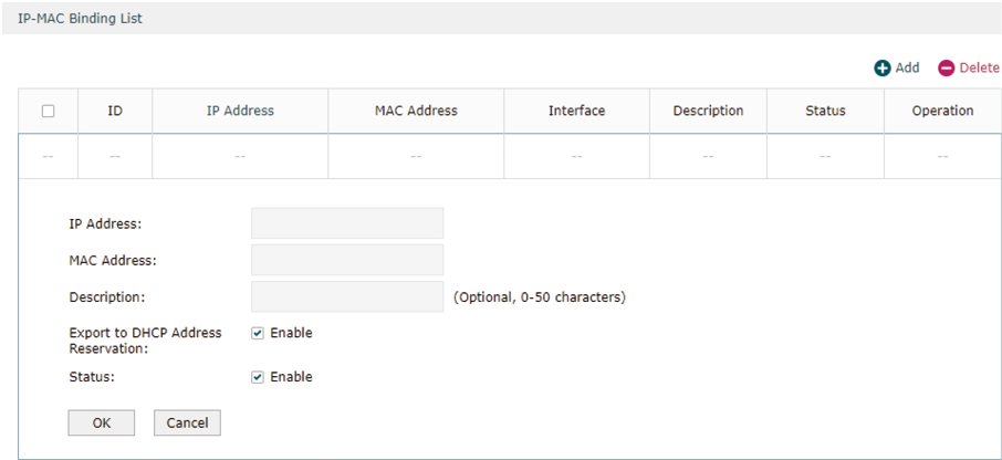
2)Configure the following parameters on this page.
|
IP Address |
Enter an IP address to be bound. |
|
MAC Address |
Enter a MAC address to be bound. |
|
Description |
Give a description for identification. |
|
Export to DHCP Address Reservation |
Choose to whether export the entry to the DHCP Address Reservation list. |
|
Status |
Enable this entry. Only when the status is Enable will this entry be effective. |
3)Click OK and the added entry will be displayed in the list.
Adding IP-MAC Binding Entries via ARP Scanning
If you want to get the IP addresses and MAC addresses of the hosts quickly, you can use ARP Scanning to facilitate your operation.
|
|
Note: Before using this feature, make sure that your network is safe and the hosts are not suffering from ARP attacks at present; otherwise, you may obtain incorrect IP-MAC Binding entries. If your network is being attacked, it’s recommended to bind the entries manually. |
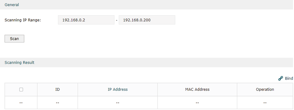
Choose the menu Firewall > Anti ARP Spoofing > ARP Scanning to load the following page.
Figure 2-3 Add IP-MAC Binding Etries via ARP Scanning
Follow the steps below to add IP-MAC Binding entries via ARP Scanning.
1)Click Scan and the following window will pop up.
Figure 2-4 ARP Scanning Process

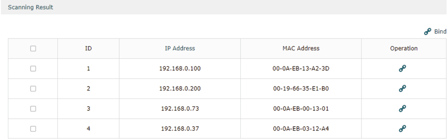
2)Wait for a moment without any operation. The scanning result will be displayed in the following table. Click  to export the corresponding entry to the IP-MAC Binding table, or select multiple entries and click
  to export the entries to the IP-MAC Binding table in batch.
Figure 2-5 ARP Scanning Result
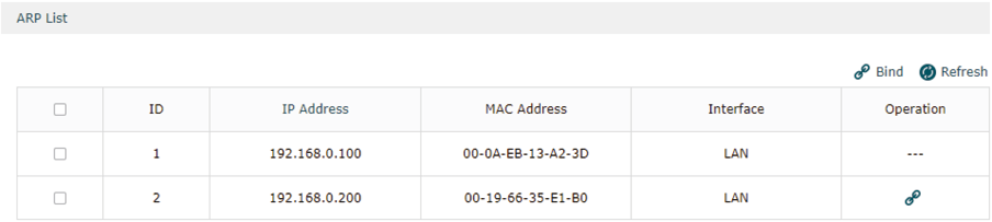
Also, you can go to Firewall > Anti ARP Spoofing > ARP List to view and bind the ARP Scanning entries. The ARP Scanning list displays all the historical scanned entries. Click to export the corresponding entry to the IP-MAC Binding table, or select multiple entries and click to export the entries to the IP-MAC Binding table in batch.
Figure 2-6 ARP List
2.1.2Enable Anti ARP Spoofing
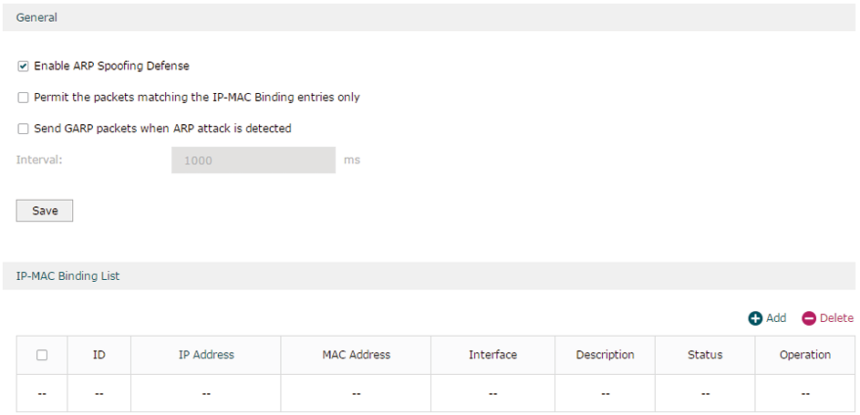
Choose the menu Firewall > Anti ARP Spoofing > IP-MAC Binding to load the following page.
Figure 2-1 IP-MAC Binding-General Config
Follow the steps below to configure Anti ARP Spoofing rule:
1)In the General section, enable ARP Spoofing Defense globally. With this option enabled, the router can protect its ARP table from being falsified by ARP spoofing packets.
2)Choose whether to enable the two sub functions.
|
Permit the packets matching the IP-MAC Binding entries only |
With this option enabled, when receiving a packet, the router will check whether the IP address, MAC address and receiving interface match any of the IP-MAC Binding entries. Only the matched packets will be forwarded. |
|
Send GARP packets when ARP attack is detected |
With this option enabled, the router will send GARP packets to the hosts if it detects ARP spoofing packets on the network. The GARP packets will inform the hosts of the correct ARP information, which is used to replace the wrong ARP information in the hosts. |
|
Interval |
If the Send GARP packets when ARP attack is detected is enabled, configure the time interval for sending GARP packets. The valid values are from 1 to 10000 milliseconds. |
3)Click Save.
|
|
Note: Before enabling “Permit the packets matching the IP-MAC Binding entries only”, you should make sure that your management host is in the IP-MAC Binding list. Otherwise, you cannot log in to the Web management page of the router. If this happens, restore your router to factory defaults and then log in using the default login credentials. |
2.2Configuring Attack Defense
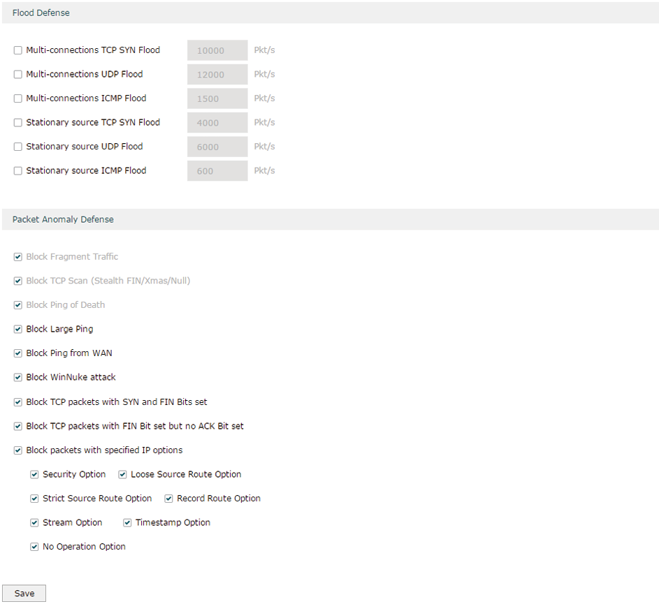
Choose the menu Firewall > Attack Defense > Attack Defense to load the following page.
Figure 2-2 Attack Defense
Follow the steps below to configure Attack Defense.
1)In the Flood Defense section, check the box and configure the corresponding parameters to enable your desired feature. By default, all the options are disabled. For details, refer to the following table:
|
Multi-connections TCP SYN Flood |
With this feature enabled, the router will filter the subsequent TCP SYN packets if the number of this kind of packets reaches the specified threshold. The valid threshold ranges from 100 to 99999. |
|
Multi-connections UDP Flood |
With this feature enabled, the router will filter the subsequent UDP packets if the number of this kind of packets reaches the specified threshold. The valid threshold ranges from 100 to 99999. |
|
Multi-connections ICMP Flood |
With this feature enabled, the router will filter the subsequent ICMP packets if the number of this kind of packets reaches the specified threshold. The valid threshold ranges from 100 to 99999. |
|
Stationary source TCP SYN Flood |
With this feature enabled, the router will filter the subsequent stationary source TCP SYN packets if the number of this kind of packets reaches the specified threshold. The valid threshold ranges from 100 to 99999. |
|
Stationary source UDP Flood |
With this feature enabled, the router will filter the subsequent stationary source UDP SYN packets if the number of this kind of packets reaches the specified threshold. The valid threshold ranges from 100 to 99999. |
|
Stationary source ICMP Flood |
With this feature enabled, the router will filter the subsequent stationary source ICMP SYN packets if the number of this kind of packets reaches the specified threshold. The valid threshold ranges from 100 to 99999. |
2)In the Packet Anomaly Defense section, directly check the box to enable your desired feature. By default, all the options are enabled. For details, refer to the following table:
|
Block Fragment Traffic |
With this option enabled, the router will filter the fragment packets. |
|
Block TCP Scan (Stealth FIN/Xmas/Null) |
With this option enabled, the router will filter the TCP scan packets of Stealth FIN, Xmas and Null. |
|
Block Ping of Death |
With this option enabled, the router will block Ping of Death attack. Ping of Death attack means that the attacker sends abnormal ping packets larger than 65535 bytes to cause system crash on the target computer. |
|
Block Large Ping |
With this option enabled, the router will block Large Ping attacks. Large Ping attack means that the attacker sends multiple ping packets larger than 1500 bytes to cause the system crash on the target computer. |
|
Block Ping from WAN |
With this option enabled, the router will block the ICMP request from WAN. |
|
Block WinNuke attack |
With this option enabled, the router will block WinNuke attacks. WinNuke attack refers to a remote denial-of-service attack (DoS) that affects some Windows operating systems, such as the Windows 95 and Windows N. The attacker sends a string of OOB (Out of Band) data to the target computer on TCP port 137, 138 or 139, causing system crash or Blue Screen of Death. |
|
Block TCP packets with SYN and FIN Bits set |
With this option enabled, the router will filter the TCP packets with both SYN Bit and FIN Bit set. |
|
Block TCP packets with FIN Bit set but no ACK Bit set |
With this option enabled, the router will filter the TCP packets with FIN Bit set but without ACK Bit set. |
|
Block packets with specified IP options |
With this option enabled, the router will filter the packets with specified IP options. You can choose the options according to your needs. |
3)Click Save to save the settings.
2.3Configuring MAC Filtering
To complete MAC Filtering configuration, there are two steps. First, add MAC Filtering entries to the MAC Filtering List. Then configure the filtering rule for these entries.
|
|
Note: In case MAC Filtering causes access problems to the currently connected devices, it’s recommended to add and verify the MAC Filtering entries first before configuring the filtering rule. |
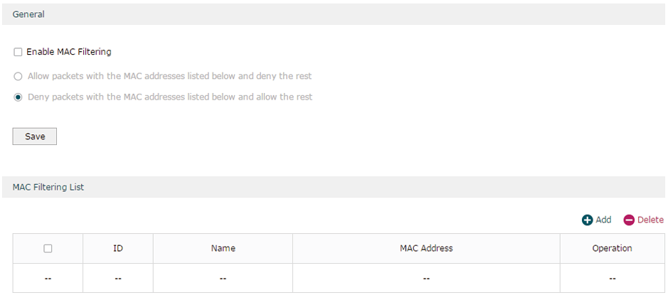
Choose the menu Firewall > MAC Filtering > MAC Filtering to load the following page.
Figure 2-3 MAC Filtering
Follow the steps below to configure MAC Filtering:
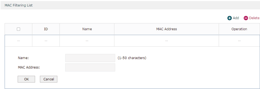
1)In the MAC Filtering List section, click Add to add MAC Filtering entries to the MAC Filtering list. Specify a name and enter the MAC address in the format xx-xx-xx-xx-xx-xx. Click OK.
Figure 2-4 MAC Filtering
2)In the General section, enable MAC Filtering and select the filtering rule. Click Save, and the filtering rule will be applied to all entries in this list.
|
Enable MAC Filtering |
Check the box to enable MAC Filtering. |
|
Allow packets with the MAC addresses listed below and deny the rest |
Choose whether to select this filtering rule. With this rule selected, the router will allow the packets with the MAC addresses in the MAC Filtering List and deny other packets. |
|
Deny packets with the MAC addresses listed below and allow the rest |
Choose whether to select this filtering rule. With this rule selected, the router will deny the packets with the MAC addresses in the MAC Filtering List and allow other packets. |
|
|
Note: MAC Filtering rules take effect on the LAN interface instead of the WAN interface. |
2.4Configuring Access Control
Choose the menu Firewall > Access Control > Access Control and click Add to load the following page.
Figure 2-5 Access Control
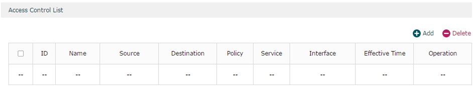
This table displays the Access Control entries. Follow the steps below to add a new Access Control entry.
1)Click Add and the following page will appear.
Figure 2-6 Access Control
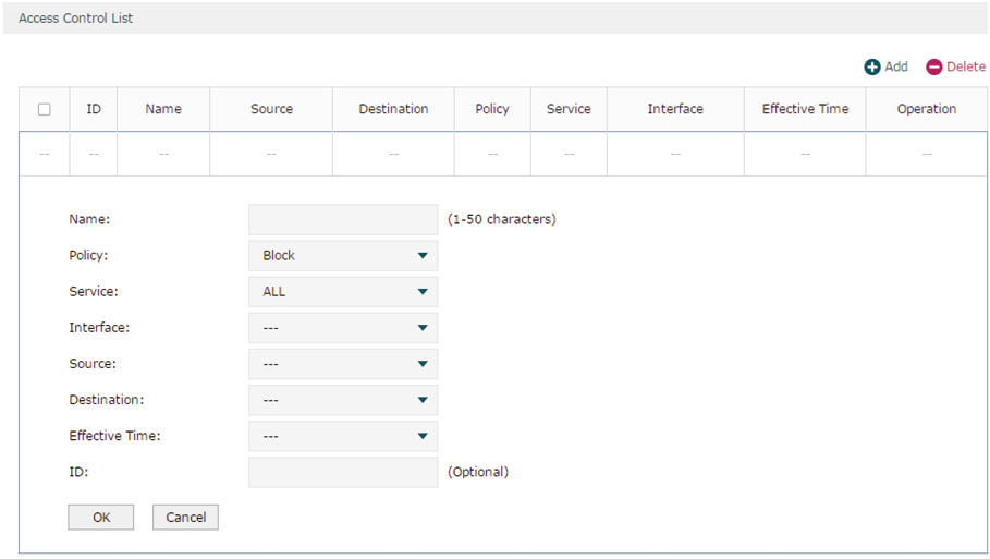
2)Configure the required parameters and click OK:
|
Name |
Specify a name for the rule. It can be 50 characters at most. The name of each entry cannot be repeated. |
|
Policy |
Select whether to block or allow the packets matching the rule to access the network. |
|
Service |
Select the effective service for the rule. The service referenced here can be created on the Preferences > Service Type page. |
|
Interface |
Select the effective interface for the rule. |
|
Source |
Select an IP group to specify the source address range for the rule. The IP group referenced here can be created on the Preferences > IP Group page. |
|
Destination |
Select an IP group to specify the destination address range for the rule. The IP group referenced here can be created on the Preferences > IP Group page. |
|
Effective Time |
Select the effective time for the rule. The effective time referenced here can be created on the Preferences > Time Range page. |
|
ID |
Specify a rule ID. A smaller ID means a higher priority. This value is optional, and the newly added rule without this value configured will get the largest ID among all rules, which means the newly added rule has the lowest priority. |
3.1Example for Anti ARP Spoofing
3.1.1Network Requirements
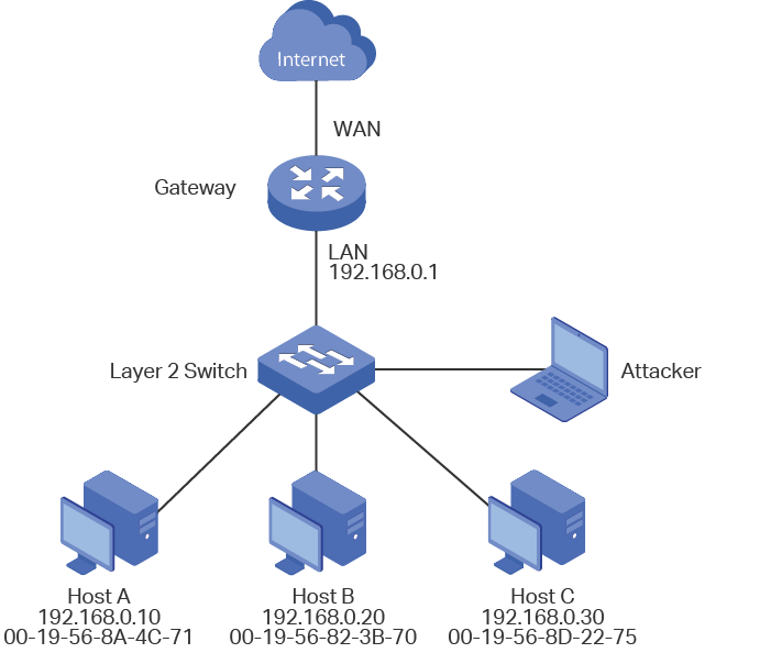
In the diagram below, several hosts are connected to the network via a layer 2 switch, and the router is the gateway of this network. Since there exists the possibility that the attacker will launch a series of ARP attacks, it is required to configure the router to protect itself and the terminal hosts from the ARP attacks.
Figure 3-1 Network Topology
3.1.2Configuration Scheme
The attacker can launch three types of ARP attacks: cheating gateway, imitating gateway and cheating terminal hosts. The following section introduces the three ARP attacks and the corresponding solutions.
Cheating Gateway
Cheating gateway attack is aimed at the router.
The attacker pretends to be legal terminal hosts and sends fake ARP packets to the router, cheating the router into recording wrong ARP maps of the hosts. As a result, packets from the gateway cannot be correctly sent to the hosts. To protect the router from this kind of attack, you can configure Anti ARP Spoofing on the router.
Imitating Gateway and Cheating Hosts
These two attacks are aimed at the terminal hosts.
Imitating Gateway means that the attacker imitates the gateway and sends fake ARP packets to the hosts. As a result, the hosts record wrong ARP map of the gateway and cannot send packets to the router correctly.
Cheating Hosts means that the attacker pretends to be a legal host and sends fake ARP packets to other hosts. As a result, the cheated hosts record an incorrect ARP map of the legal host and cannot send packets to legal host correctly.
To protect the hosts from the attacks above, it is recommend to take both of the precautions below.
»Configure the firewall feature on the hosts.
»Configure the router to send GARP packets to the hosts when the router detects ARP attacks. The GARP packets will inform the hosts of the correct ARP maps, and the wrong ARP maps in the hosts will be replaced by the correct ones.
In conclusion, to protect the network from ARP attacks, we should make sure both the router and the hosts are configured with the relevant ARP defense features. Here we introduce how to configure Anti ARP Spoofing on the router. There are mainly three steps:
1)Get the IP and MAC addresses of the legal hosts and bind them to the IP-MAC Binding list.
2)Enable Anti ARP Spoofing.
3)Configure the router to send GARP packets when ARP attacks are detected.
3.1.3Configuration Procedure
Follow the steps below to configure Anti ARP Spoofing on the router:
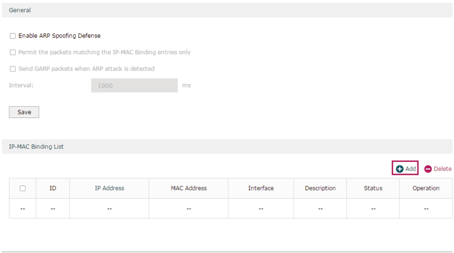
1)Choose the menu Firewall > Anti ARP Spoofing > IP-MAC Binding to load the following page. In the IP-MAC Binding List section, click Add.
Figure 3-2 Anti ARP Spoofing Page
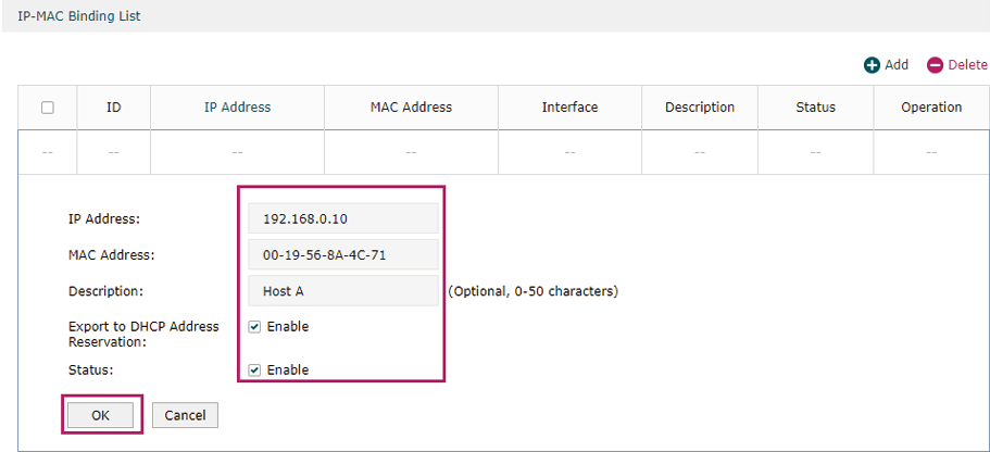
2)The following page will appear. Enter the IP address and MAC address of Host A, give a description “Host A” for this entry. Since the IP address 192.168.0.10 has been used by Host A, we keep Export to DHCP Address Reservation as “Enable” to preserve this IP address from being assigned to other hosts. Keep Status of this entry as “Enable”. Click OK.
Figure 3-3 Add IP-MAC Binding Entry
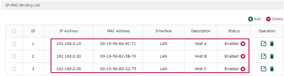
3)Add the IP-MAC Binding entries for Host B and Host C as introduced above, and verify your configurations.
Figure 3-4 Verify IP-MAC Binding Entires
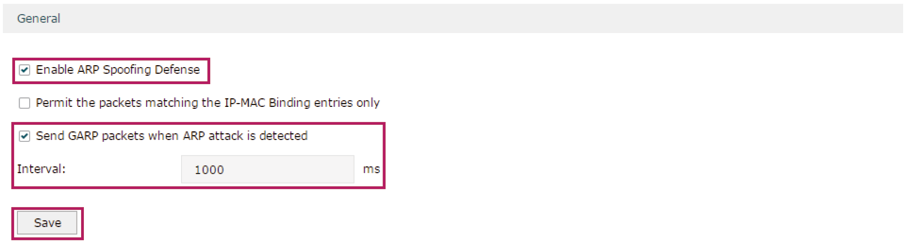
4)In the General section on the same page, check the boxes to enable ARP Spoofing Defense and Send GARP packets when ARP attack is detected, and keep the interval as 1000 milliseconds. Click Save.
Figure 3-5 Configure Anti ARP Spoofing
3.2Example for MAC Filtering
3.2.1Network Requirements
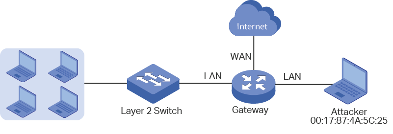
In the diagram below, the router is the gateway of the network. The network administrator now detects some abnormal attack packets from a host whose MAC address is 00:17:87:4A:5C:25. To protect the devices from being attacked, it is required that all packets from the attacker should be dropped when passing through the router.
Figure 3-1 Network Topology
3.2.2Configuration Scheme
To meet this requirement, we can configure MAC Filtering on the router to filter the packets with the MAC address of the attacker. The configuration overview is as follows:
1)Enable MAC Filtering globally and select the filtering rule as “Deny packets with the MAC addresses listed below and allow the rest“.
2)Add the MAC address of the attacker to the MAC Filtering List.
3.2.3Configuration Procedure
Follow the steps below to configure MAC Filtering on the router:
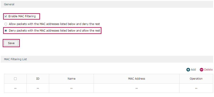
1)Choose the menu Firewall > MAC Filtering > MAC Filtering to load the following page. In the General section, enable MAC Filtering and select the filtering rule as “Deny packets with the MAC addresses listed below and allow the rest“. Click Save.
Figure 3-2 Enable MAC Filtering
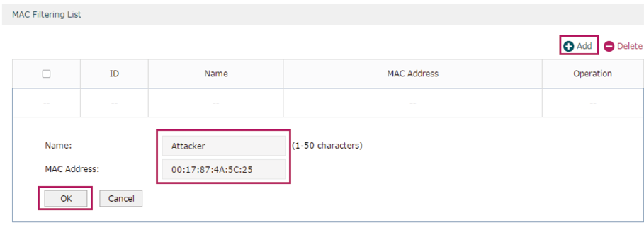
2)In the MAC Filtering List section, click Add. Specify a name for this entry and enter the attacker’s MAC address. Click OK.
Figure 3-3 Add MAC Filtering Entry
3.3Example for Access Control
3.3.1Network Requirements
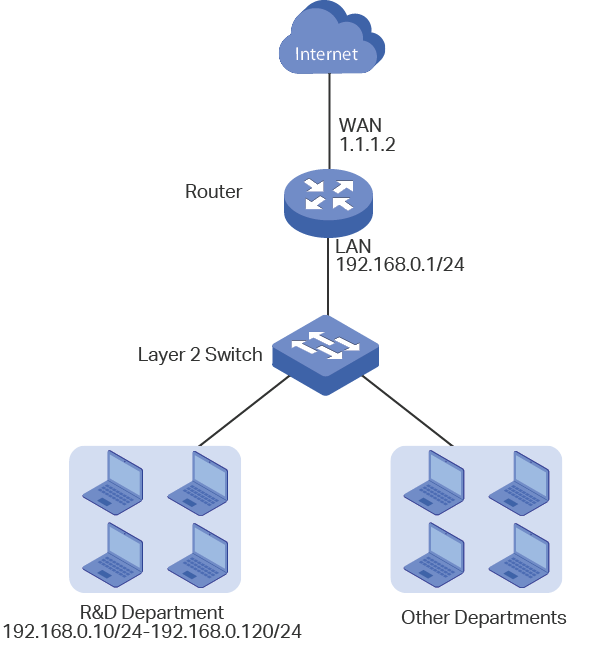
In the diagram below, the R&D and some other departments are connected to a layer 2 switch and access the internet via the router. To limit the acts of the R&D department users, such as sending emails with the exterior mailbox, it is required that the R&D users can only visit websites via HTTP and HTTPs on the internet at any time. For other departments, there is no limitation.
Figure 3-1 Network Topology
3.3.2Configuration Scheme
To meet these requirements, we can configure Access Control rules on the router to filter the specific types of packets from R&D department: only the HTTP and HTTPs packets are allowed to be sent to the internet, and other types of packets are not allowed. The configuration overview is as follows:
1)Add an IP group for the R&D department in the Preferences module.
2)By default, the HTTP service type already exists, and you need to add HTTPs to the Service Type list in the Preferences module.
3)Create two rules to allow the HTTP and HTTPs packets from the R&D department to be sent to the WAN.
4)Since visiting the internet needs DNS service, add a rule to allow the DNS packets to be sent to the WAN. DNS service is already in the Service Type list by default.
5)Create a rule to block all packets from the R&D department to the WAN. This rule should have the lowest priority among all the rules.
3.3.3Configuration Procedure
Follow the steps below to complete the configuration:
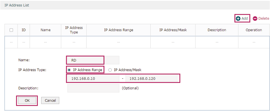
1)Choose the menu Preferences > IP Group > IP Address to load the configuration page, and click Add. Specify a name RD, select IP Address Range and enter the IP address range of the R&D department. Click OK.
Figure 3-2 Configure IP Address Range
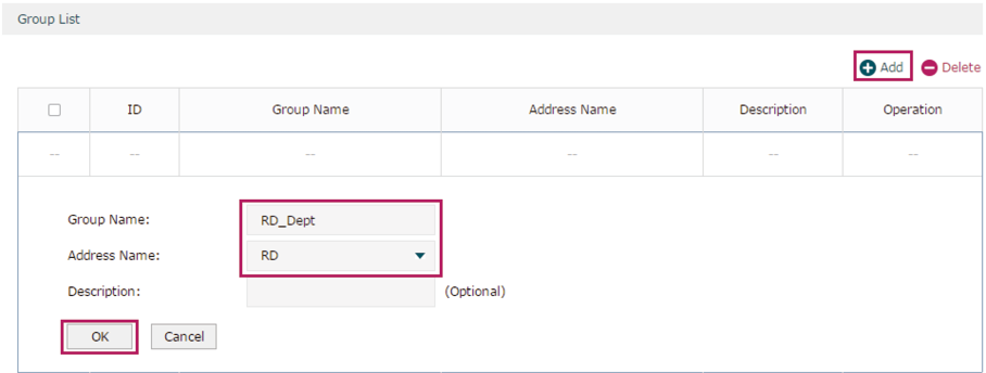
2)Choose the menu Preferences > IP Group > IP Group to load the configuration page, and click Add. Specify a group name “RD_Dept”, select the preset address range "RD” and click OK.
Figure 3-3 Configure IP Group
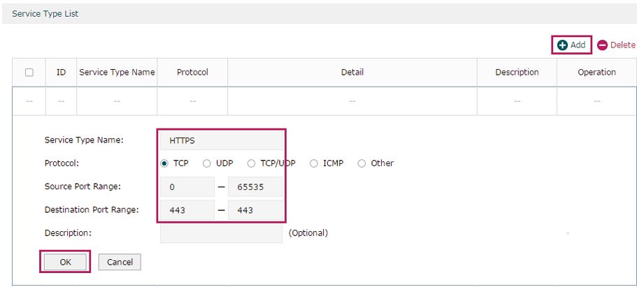
3)Choose the menu Preferences > Service Type > Service Type to load the configuration page, and click Add. Specify the service type name as “HTTPS”, select the protocol as “TCP”, specify the source port range as “0-65535” and destination port range as “443-443”, and click OK.
Figure 3-4 Configure HTTPS Service Type
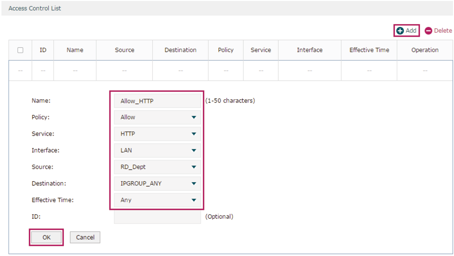
4)Choose the menu Firewall > Access Control > Access Control to load the configuration page, and click Add. Specify a name for this rule. Select “Allow” as the rule policy, “HTTP” as the service type, “LAN” as the effective interface, “RD_Dept” as the source IP group, “IPGROUP_ANY” as the destination IP group, and “Any” as the effective time. Click OK.
This rule means that all the HTTP packets from the R&D department are allowed to be transmitted from LAN to the internet at any time.
Figure 3-5 Configure Allow Rule for HTTP Service
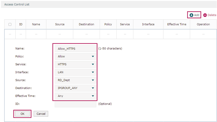
5)Choose the menu Firewall > Access Control > Access Control to load the configuration page, and click Add. Specify a name for this rule. Select “Allow” as the rule policy, “HTTPS” as the service type, “LAN” as the effective interface, “RD_Dept” as the source IP group, “IPGROUP_ANY” as the destination IP group, and “Any” as the effective time. Click OK.
This rule means that all the HTTPS packets from the R&D department are allowed to be sent from the LAN to the internet at any time.
Figure 3-6 Configure Allow Rule for HTTPS Service
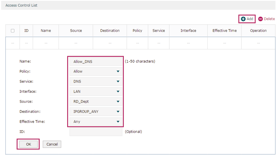
6)Choose the menu Firewall > Access Control > Access Control to load the configuration page, and click Add. Specify a name for this rule. Select “Allow” as the rule policy, “DNS” as the service type, “LAN” as the effective interface, “RD_Dept” as the source IP group, “IPGROUP_ANY” as the destination IP group, and “Any” as the effective time. Click OK.
This rule means that all DNS packets from the R&D department are allowed to be sent from the LAN to the internet at any time.
Figure 3-7 Configure Allow Rule for DNS Service
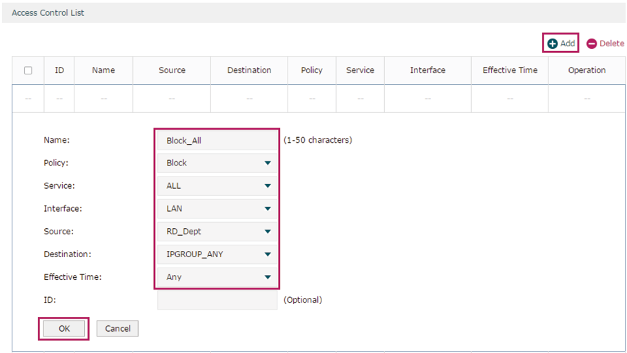
7)Choose the menu Firewall > Access Control > Access Control to load the configuration page, and click Add. Specify a name for this rule. Select “Block” as the rule policy, “ALL” as the service type, “LAN” as the effective interface, “RD_Dept” as the source IP group, “IPGROUP_ANY” as the destination IP group, and “Any” as the effective time. Click OK.
This rule means that all packets from the R&D department are blocked from being sent from the LAN to the internet at all times.
Figure 3-8 Configure Block Rule for ALL Services
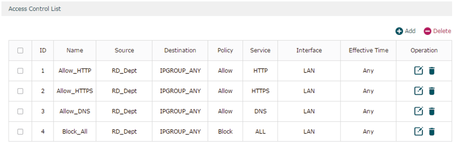
8)Verify your configuration result. In the Access Control List, the rule with a smaller ID has a higher priority. Since the router matches the rules beginning with the highest priority, make sure the three Allow rules have the smaller ID numbers compared with the Block rule. In this way, the router checks whether the received packet matches the three Allow rules first, and only packets that do not match any of the Allow rules will be blocked.
Figure 3-9 Verify Configuration Result