Configuring ACL
CHAPTERS
3. Configuration Example for ACL
4. Appendix: Default Parameters
|
|
This guide applies to: T1500G-8T v2 or above, T1500G-10PS v2 or above, T1500G-10MPS v2 or above, T1500-28PCT v3 or above, T1600G-18TS v2 or above, T1600G-28PS v3 or above, T1600G-28TS v3 or above, T1600G-52TS v3 or above, T1600G-52PS v3 or above, T1700X-16TS v3 or above, T1700G-28TQ v3 or above, T2500G-10TS v2 or above, T2600G-18TS v2 or above, T2600G-28TS v3 or above, T2600G-28MPS v3 or above, T2600G-28SQ v1 or above, T2600G-52TS v3 or above. |

ACL (Access Control List) filters traffic as it passes through a switch, and permits or denies packets crossing specified interfaces or VLANs. It accurately identifies and processes the packets based on the ACL rules. In this way, ACL helps to limit network traffic, manage network access behaviors, forward packets to specified ports and more.
To configure ACL, follow these steps:
1)Configure a time range during which the ACL is in effect.
2)Create an ACL and configure the rules to filter different packets.
3)Bind the ACL to a port or VLAN to make it effective.
Configuration Guidelines
A packet “matches” an ACL rule when it meets the rule’s matching criteria. The resulting action will be either to “permit” or “deny” the packet that matches the rule.
If no ACL rule is configured, the packets will be forwarded without being processed by the ACL. If there is configured ACL rules and no matching rule is found, the packets will be dropped.
2.1Using the GUI
2.1.1Configuring Time Range
Some ACL-based services or features may need to be limited to take effect only during a specified time period. In this case, you can configure a time range for the ACL. For details about Time Range configuration, please refer to Managing System.
2.1.2Creating an ACL
You can create different types of ACL and define the rules based on source MAC or IP address, destination MAC or IP address, protocol type, port number and so on.
MAC ACL: MAC ACL uses source and destination MAC address for matching operations.
IP ACL: IP ACL uses source and destination IP address, IP protocols and so on for matching operations.
Combined ACL: Combined ACL uses source and destination MAC address, and source and destination IP address for matching operations.
IPv6 ACL: IPv6 ACL uses source and destination IPv6 address for matching operations.
Packet Content ACL: Packet Content ACL analyzes and processes data packets based on 4 chunk match conditions, each chunk can specify a user-defined 4-byte segment carried in the packet’s first 128 bytes. Only T2600G series support this feature.
Choose the menu SECURITY > ACL > ACL Config and click  to load the following page.
Figure 2-1 Creating an ACL
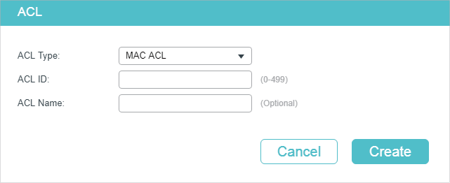
Follow these steps to create an ACL:
1)Choose one ACL type and enter a number to identify the ACL.
2)(Optional) Assign a name to the ACL.
3)Click Create.
|
|
Note: The supported ACL type and ID range varies on different switch models. Please refer to the on-screen information. |

2.1.3Configuring ACL Rules
|
|
Note: Every ACL has an implicit deny all rule at the end of an ACL rule list. That is, if an ACL is applied to a packet and none of the explicit rules match, then the final implicit deny all rule takes effect and the packet is dropped. |
The created ACL will be displayed on the SECURITY > ACL > ACL Config page.
Figure 2-2 Editing ACL
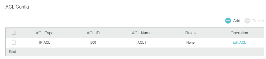
Click Edit ACL in the Operation column. Then you can configure rules for this ACL.
The following sections introduce how to configure MAC ACL, IP ACL, Combined ACL, IPv6 ACL and Packet Content ACL.
Configuring MAC ACL Rule
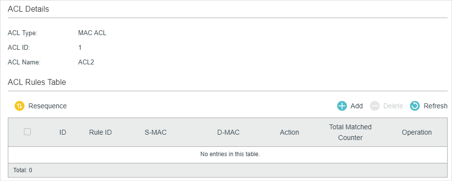
Click Edit ACL for a MAC ACL entry to load the following page.
Figure 2-3 Configuring the MAC ACL Rule
In ACL Rules Table section, click  and the following page will appear.
Figure 2-4 Configuring the MAC ACL Rule
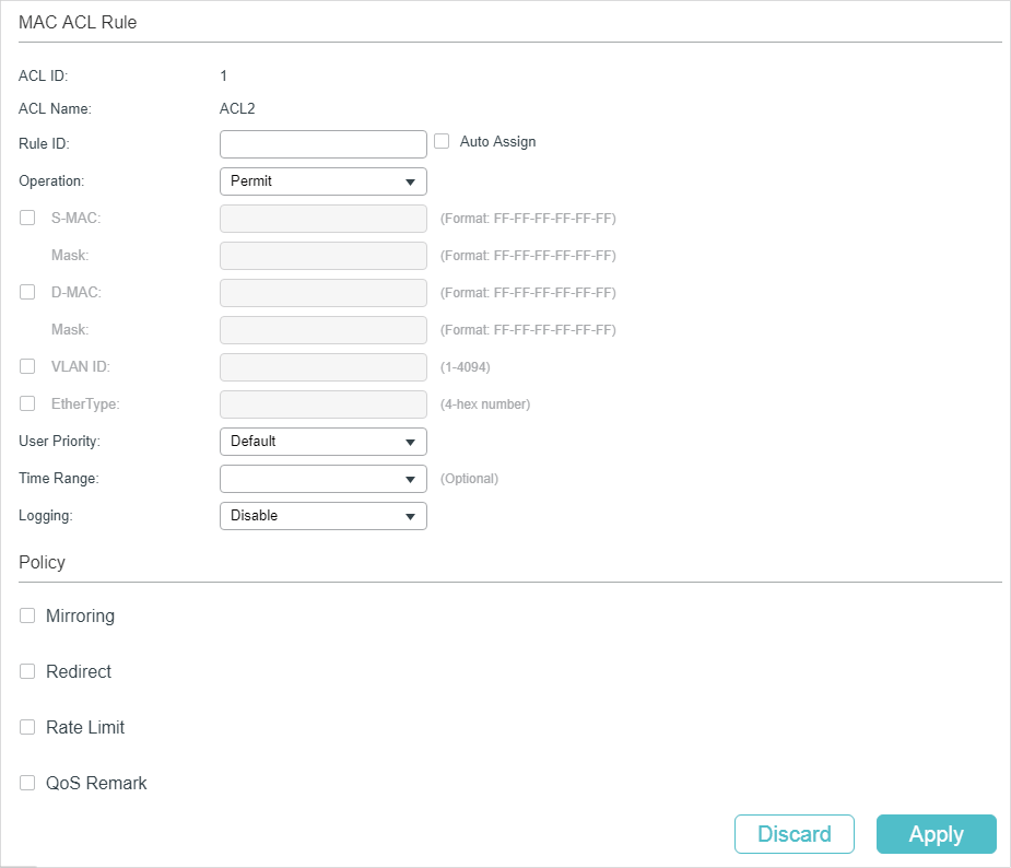
Follow these steps to configure the MAC ACL rule:
1)In the MAC ACL Rule section, configure the following parameters:
|
Rule ID |
Enter an ID number to identify the rule. It should not be the same as any current rule ID in the same ACL. For the convenience of inserting new rules to an ACL, you should set the appropriate interval between rule IDs. If you select Auto Assign, the rule ID will be assigned automatically by the system and the default increment between neighboring rule IDs is 5. |
|
Operation |
Select an action to be taken when a packet matches the rule. Permit: To forward the matched packets. Deny: To discard the matched packets. |
|
S-MAC/Mask |
Enter the source MAC address with a mask. A value of 1 in the mask indicates that the corresponding bit in the address will be matched. |
|
D-MAC/Mask |
Enter the destination MAC address with a mask. A value of 1 in the mask indicates that the corresponding bit in the address will be matched. |
|
VLAN ID |
Enter the ID number of the VLAN with which packets will match. The valid range is 1-4094. If the ACL is bound to a VLAN, the system requires the VLAN ID of a packet to match the ID of the VLAN instead of the ID listed here. |
|
EtherType |
Specify the EtherType to be matched using 4 hexadecimal numbers. |
|
User Priority |
Specify the User Priority to be matched. |
|
Time Range |
Select a time range during which the rule will take effect. The default value is No Limit, which means the rule is always in effect. The Time Range referenced here can be created on the SYSTEM > Time Range page. |
|
Logging |
Enable Logging function for the ACL rule. Then the times that the rule is matched will be logged every 5 minutes and a related trap will be generated. You can refer to Total Matched Counter in the ACL Rules Table to view the matching times. |
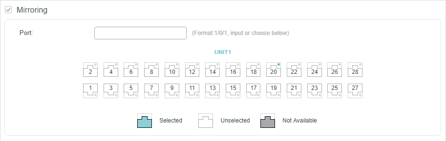
2)In the Policy section, enable or disable the Mirroring feature for the matched packets. With this option enabled, choose a destination port to which the packets will be mirrored.
Figure 2-5 Configuring Mirroring
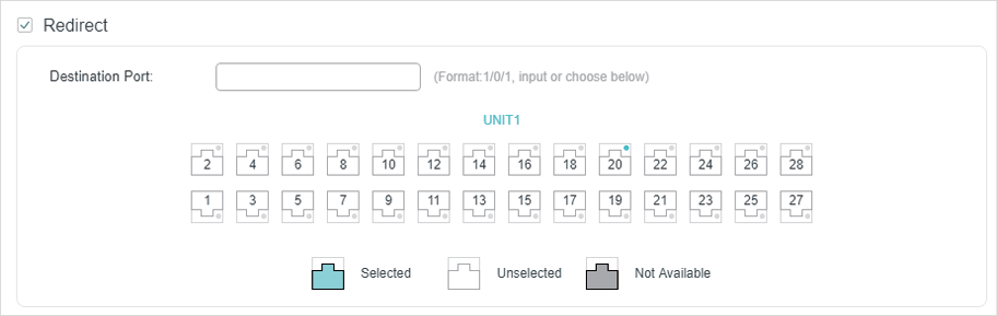
3)In the Policy section, enable or disable the Redirect feature for the matched packets. With this option enabled, choose a destination port to which the packets will be redirected.
Figure 2-6 Configuring Redirect
|
|
Note: In the Mirroring feature, the matched packets will be copied to the destination port and the original forwarding will not be affected. While in the Redirect feature, the matched packets will be forwarded only on the destination port. |
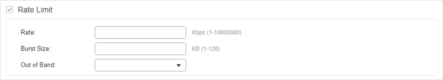
4)In the Policy section, enable or disable the Rate Limit feature for the matched packets. With this option enabled, configure the related parameters.
Figure 2-7 Configuring Rate Limit
|
Rate |
Specify the transmission rate for the matched packets. |
|
Burst Size |
Specify the maximum number of bytes allowed in one second. |
|
Out of Band |
Select the action for the packets whose rate is beyond the specified rate. None: The packets will be forwarded normally. Drop: The packets will be discarded. Remark DSCP: You can specify a DSCP value, and the DSCP field of the packets will be changed to the specified one. T1500 series, T1600G-18TS, T1600G-28TS, T1600G-28PS, T1600G-52TS v4 and T1600G-52PS v4 do not support this option. |
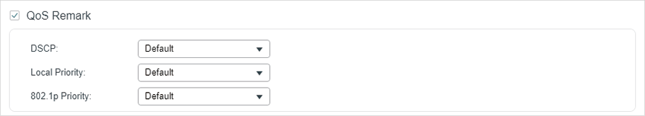
5)In the Policy section, enable or disable the QoS Remark feature for the matched packets. With this option enabled, configure the related parameters, and the remarked values will take effect in the QoS processing on the switch.
Figure 2-8 Configuring QoS Remark
|
DSCP |
Specify the DSCP field for the matched packets. The DSCP field of the packets will be changed to the specified one. |
|
Local Priority |
Specify the local priority for the matched packets. The local priority of the packets will be changed to the specified one. |
|
802.1p Priority |
Specify the 802.1p priority for the matched packets. The 802.1p priority of the packets will be changed to the specified one. |
6)Click Apply.
Configuring IP ACL Rule
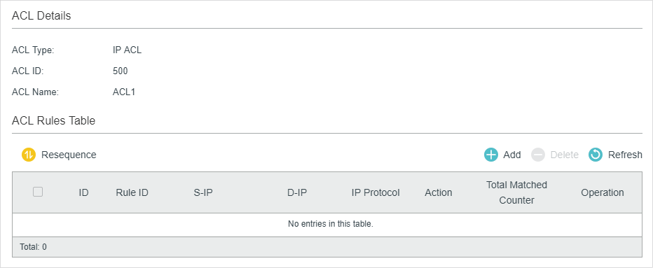
Click Edit ACL for an IP ACL entry to load the following page.
Figure 2-9 Configuring the IP ACL Rule
In ACL Rules Table section, click and the following page will appear.
Figure 2-10 Configuring the IP ACL Rule
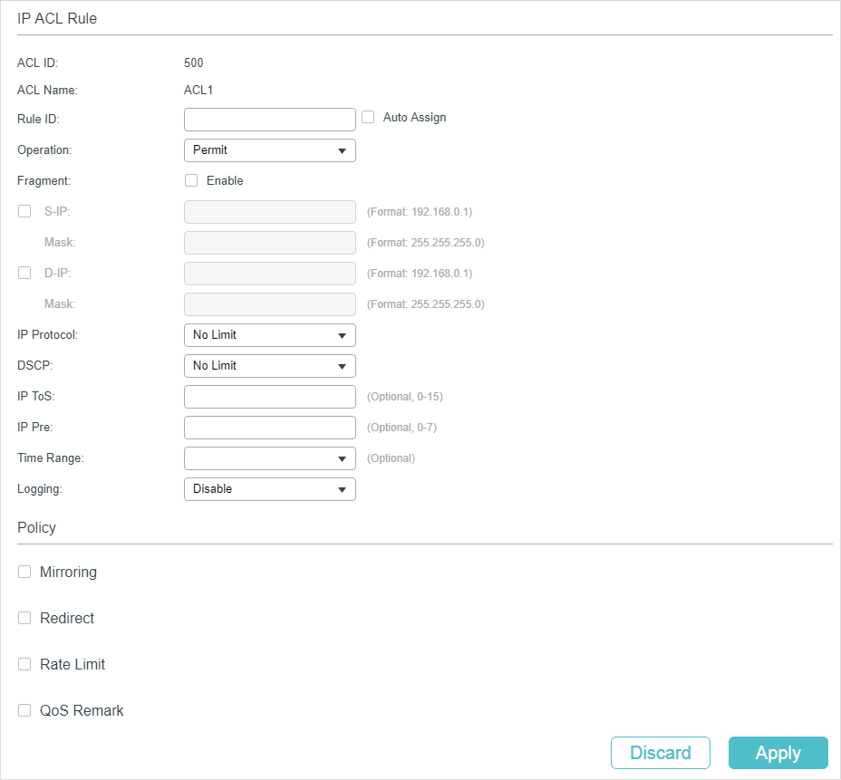
Follow these steps to configure the IP ACL rule:
1)In the IP ACL Rule section, configure the following parameters:
|
Rule ID |
Enter an ID number to identify the rule. It should not be the same as any current rule ID in the same ACL. For the convenience of inserting new rules to an ACL, you should set the appropriate interval between rule IDs. If you select Auto Assign, the rule ID will be assigned automatically by the system and the default increment between neighboring rule IDs is 5 |
|
Operation |
Select an action to be taken when a packet matches the rule. Permit: To forward the matched packets. Deny: To discard the matched packets. |
|
Fragment |
With this option selected, the rule will be applied to all fragment packets except for the last fragment packet in the fragment packet group. T1500 series, T1600G-18TS, T1600G-28TS, T1600G-28PS, T1600G-52TS v4 and T1600G-52PS v4 do not support this option. |
|
S-IP/Mask |
Enter the source IP address with a mask. A value of 1 in the mask indicates that the corresponding bit in the address will be matched. |
|
D-IP/Mask |
Enter the destination IP address with a mask. A value of 1 in the mask indicates that the corresponding bit in the address will be matched. |
|
IP Protocol |
Select a protocol type from the drop-down list. The default is No Limit, which indicates that packets of all protocols will be matched. You can also select User-defined to customize the IP protocol. |
|
TCP Flag |
If TCP protocol is selected, you can configure the TCP Flag to be used for the rule’s matching operations. There are six flags and each has three options, which are *, 0 and 1. The default is *, which indicates that the flag is not used for matching operations. URG: Urgent flag. ACK: Acknowledge flag. PSH: Push flag. RST: Reset flag. SYN: Synchronize flag. FIN: Finish flag. |
|
S-Port / D-Port |
If TCP/UDP is selected as the IP protocol, specify the source and destination port number with a mask. Value: Specify the port number. Mask: Specify the port mask with 4 hexadacimal numbers. |
|
DSCP |
Specify a DSCP value to be matched between 0 and 63. The default is No Limit. |
|
IP ToS |
Specify an IP ToS value to be matched between 0 and 15. The default is No Limit. |
|
IP Pre |
Specify an IP Precedence value to be matched to be matched between 0 and 7. The default is No Limit. |
|
Time Range |
Select a time range during which the rule will take effect. The default value is No Limit, which means the rule is always in effect. The Time Range referenced here can be created on the SYSTEM > Time Range page. |
|
Logging |
Enable Logging function for the ACL rule. Then the times that the rule is matched will be logged every 5 minutes and a related trap will be generated. You can refer to Total Matched Counter in the ACL Rules Table to view the matching times. |
2)In the Policy section, enable or disable the Mirroring feature for the matched packets. With this option enabled, choose a destination port to which the packets will be mirrored.
Figure 2-11 Configuring Mirroring
3)In the Policy section, enable or disable the Redirect feature for the matched packets. With this option enabled, choose a destination port to which the packets will be redirected.
Figure 2-12 Configuring Redirect
|
|
Note: In the Mirroring feature, the matched packets will be copied to the destination port and the original forwarding will not be affected. While in the Redirect feature, the matched packets will be forwarded only on the destination port. |
4)In the Policy section, enable or disable the Rate Limit feature for the matched packets. With this option enabled, configure the related parameters.
Figure 2-13 Configuring Rate Limit
|
Rate |
Specify the transmission rate for the matched packets. |
|
Burst Size |
Specify the maximum number of bytes allowed in one second. |
|
Out of Band |
Select the action for the packets whose rate is beyond the specified rate. None: The packets will be forwarded normally. Drop: The packets will be discarded. Remark DSCP: You can specify a DSCP value, and the DSCP field of the packets will be changed to the specified one. T1500 series, T1600G-18TS, T1600G-28TS, T1600G-28PS, T1600G-52TS v4 and T1600G-52PS v4 do not support this option. |
5)In the Policy section, enable or disable the QoS Remark feature for the matched packets. With this option enabled, configure the related parameters, and the remarked values will take effect in the QoS processing on the switch.
Figure 2-14 Configuring QoS Remark
|
DSCP |
Specify the DSCP field for the matched packets. The DSCP field of the packets will be changed to the specified one. |
|
Local Priority |
Specify the local priority for the matched packets. The local priority of the packets will be changed to the specified one. |
|
802.1p Priority |
Specify the 802.1p priority for the matched packets. The 802.1p priority of the packets will be changed to the specified one. |
6)Click Apply.
Configuring Combined ACL Rule
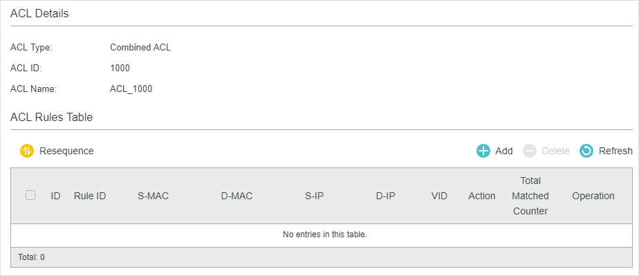
Click Edit ACL for a Combined ACL entry to load the following page.
Figure 2-15 Configuring the Combined ACL Rule
In ACL Rules Table section, click and the following page will appear.
Figure 2-16 Configuring the Combined ACL Rule
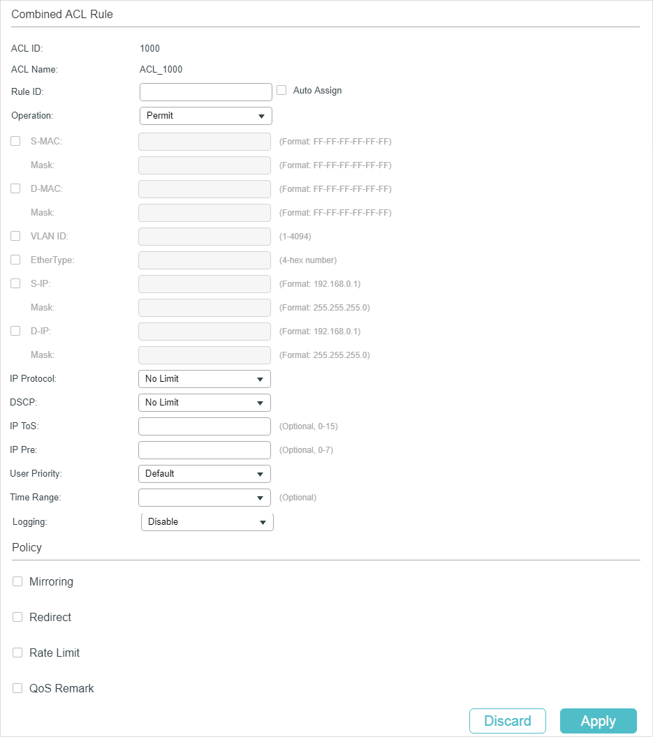
Follow these steps to configure the Combined ACL rule:
1)In the Combined ACL Rule section, configure the following parameters:
|
Rule ID |
Enter an ID number to identify the rule. It should not be the same as any current rule ID in the same ACL. For the convenience of inserting new rules to an ACL, you should set the appropriate interval between rule IDs. If you select Auto Assign, the rule ID will be assigned automatically by the system and the default increment between neighboring rule IDs is 5 |
|
Operation |
Select an action to be taken when a packet matches the rule. Permit: To forward the matched packets. Deny: To discard the matched packets. |
|
S-MAC/Mask |
Enter the source MAC address with a mask. A value of 1 in the mask indicates that the corresponding bit in the address will be matched. |
|
D-MAC/Mask |
Enter the destination IP address with a mask. A value of 1 in the mask indicates that the corresponding bit in the address will be matched. |
|
VLAN ID |
Enter the ID number of the VLAN with which packets will match. The valid range is 1-4094. If the ACL is bound to a VLAN, the system requires the VLAN ID of a packet to match the ID of the VLAN instead of the ID listed here. |
|
EtherType |
Specify the EtherType to be matched using 4 hexadecimal numbers. |
|
S-IP/Mask |
Enter the source IP address with a mask. A value of 1 in the mask indicates that the corresponding bit in the address will be matched. |
|
D-IP/Mask |
Enter the destination IP address with a mask. A value of 1 in the mask indicates that the corresponding bit in the address will be matched. |
|
IP Protocol |
Select a protocol type from the drop-down list. The default is No Limit, which indicates that packets of all protocols will be matched. You can also select User-defined to customize the IP protocol. |
|
TCP Flag |
If TCP protocol is selected, you can configure the TCP Flag to be used for the rule’s matching operations. There are six flags and each has three options, which are *, 0 and 1. The default is *, which indicates that the flag is not used for matching operations. URG: Urgent flag. ACK: Acknowledge flag. PSH: Push flag. RST: Reset flag. SYN: Synchronize flag. FIN: Finish flag. |
|
S-Port / D-Port |
If TCP/UDP is selected as the IP protocol, specify the source and destination port number with a mask. Value: Specify the port number. Mask: Specify the port mask with 4 hexadacimal numbers. |
|
DSCP |
Specify a DSCP value to be matched between 0 and 63. The default is No Limit. |
|
IP ToS |
Specify an IP ToS value to be matched between 0 and 15. The default is No Limit. |
|
IP Pre |
Specify an IP Precedence value to be matched to be matched between 0 and 7. The default is No Limit. |
|
User Priority |
Specify the User Priority to be matched. |
|
Time Range |
Select a time range during which the rule will take effect. The default value is No Limit, which means the rule is always in effect. The Time Range referenced here can be created on the SYSTEM > Time Range page. |
|
Logging |
Enable Logging function for the ACL rule. Then the times that the rule is matched will be logged every 5 minutes and a related trap will be generated. You can refer to Total Matched Counter in the ACL Rules Table to view the matching times. |
2)In the Policy section, enable or disable the Mirroring feature for the matched packets. With this option enabled, choose a destination port to which the packets will be mirrored.
Figure 2-17 Configuring Mirroring
3)In the Policy section, enable or disable the Redirect feature for the matched packets. With this option enabled, choose a destination port to which the packets will be redirected.
Figure 2-18 Configuring Redirect
|
|
Note: In the Mirroring feature, the matched packets will be copied to the destination port and the original forwarding will not be affected. While in the Redirect feature, the matched packets will be forwarded only on the destination port. |
4)In the Policy section, enable or disable the Rate Limit feature for the matched packets. With this option enabled, configure the related parameters.
Figure 2-19 Configuring Rate Limit
|
Rate |
Specify the transmission rate for the matched packets. |
|
Burst Size |
Specify the maximum number of bytes allowed in one second. |
|
Out of Band |
Select the action for the packets whose rate is beyond the specified rate. None: The packets will be forwarded normally. Drop: The packets will be discarded. Remark DSCP: You can specify a DSCP value, and the DSCP field of the packets will be changed to the specified one. T1500 series, T1600G-18TS, T1600G-28TS, T1600G-28PS, T1600G-52TS v4 and T1600G-52PS v4 do not support this option. |
5)In the Policy section, enable or disable the QoS Remark feature for the matched packets. With this option enabled, configure the related parameters, and the remarked values will take effect in the QoS processing on the switch.
Figure 2-20 Configuring QoS Remark
|
DSCP |
Specify the DSCP field for the matched packets. The DSCP field of the packets will be changed to the specified one. |
|
Local Priority |
Specify the local priority for the matched packets. The local priority of the packets will be changed to the specified one. |
|
802.1p Priority |
Specify the 802.1p priority for the matched packets. The 802.1p priority of the packets will be changed to the specified one. |
6)Click Apply.
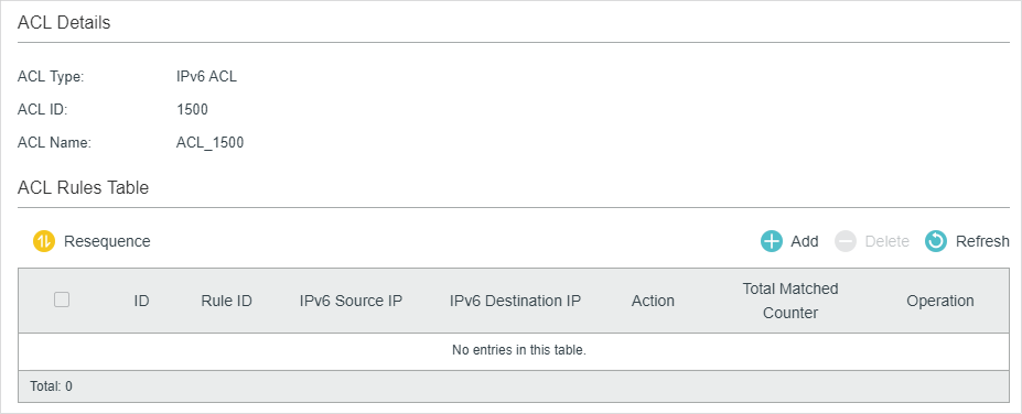
Configuring the IPv6 ACL Rule
Click Edit ACL for an IPv6 ACL entry to load the following page.
Figure 2-21 Configuring the IPv6 ACL Rule
In ACL Rules Table section, click  and the following page will appear.
Figure 2-22 Configuring the IPv6 ACL Rule
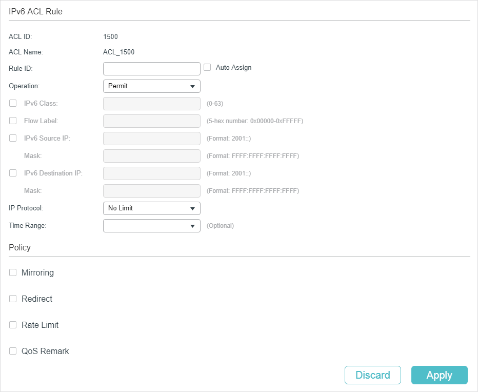
Follow these steps to configure the IPv6 ACL rule:
1)In the IPv6 ACL Rule section, configure the following parameters:
|
Rule ID |
Enter an ID number to identify the rule. It should not be the same as any current rule ID in the same ACL. For the convenience of inserting new rules to an ACL, you should set the appropriate interval between rule IDs. If you select Auto Assign, the rule ID will be assigned automatically by the system and the default increment between neighboring rule IDs is 5 |
|
Operation |
Select an action to be taken when a packet matches the rule. Permit: To forward the matched packets. Deny: To discard the matched packets. |
|
IPv6 Class |
Specify an IPv6 class value to be matched. The switch will check the class field of the IPv6 header. |
|
Flow Label |
Specify a Flow Label value to be matched. |
|
IPv6 Source IP |
Enter the source IPv6 address to be matched. All types of IPv6 address will be checked. You may enter a complete 128-bit IPv6 address but only the first 64 bits will be valid. |
|
Mask |
The mask is required if the source IPv6 address is entered. Enter the mask in complete format (for example, FFFF:FFFF:0000:FFFF). The IP address mask specifies which bits in the source IPv6 address to match the rule. A value of 1 in the mask indicates that the corresponding bit in the address will be matched. |
|
IPv6 Destination IP |
Enter the destination IPv6 address to be matched. All types of IPv6 address will be checked. You may enter a complete 128-bit IPv6 address but only the first 64 bits will be valid. |
|
Mask |
The mask is required if the destination IPv6 address is entered. Enter the complete mask (for example, FFFF:FFFF:0000:FFFF). The IP address mask specifies which bits in the source IP address to match the rule. A value of 1 in the mask indicates that the corresponding bit in the address will be matched. |
|
IP Protocol |
Select a protocol type from the drop-down list. No Limit: Packets of all protocols will be matched. UDP: Specify the source port and destination port for the UDP packet to be matched. TCP: Specify the source port and destination port for the TCP packet to be matched. User-defined: You can customize an IP protocol. |
|
S-Port / D-Port |
If TCP/UDP is selected as the IP protocol, specify the source and destination port numbers. |
|
Time Range |
Select a time range during which the rule will take effect. The default value is No Limit, which means the rule is always in effect. The Time Range referenced here can be created on the SYSTEM > Time Range page. |
2)In the Policy section, enable or disable the Mirroring feature for the matched packets. With this option enabled, choose a destination port to which the packets will be mirrored.
Figure 2-23 Configuring Mirroring
3)In the Policy section, enable or disable the Redirect feature for the matched packets. With this option enabled, choose a destination port to which the packets will be redirected.
Figure 2-24 Configuring Redirect
|
|
Note: In the Mirroring feature, the matched packets will be copied to the destination port and the original forwarding will not be affected. While in the Redirect feature, the matched packets will be forwarded only on the destination port. |
4)In the Policy section, enable or disable the Rate Limit feature for the matched packets. With this option enabled, configure the related parameters.
Figure 2-25 Configuring Rate Limit
|
Rate |
Specify the transmission rate for the matched packets. |
|
Burst Size |
Specify the maximum number of bytes allowed in one second. |
|
Out of Band |
Select the action for the packets whose rate is beyond the specified rate. None: The packets will be forwarded normally. Drop: The packets will be discarded. Remark DSCP: You can specify a DSCP value, and the DSCP field of the packets will be changed to the specified one. T1500 series, T1600G-18TS, T1600G-28TS, T1600G-28PS, T1600G-52TS v4 and T1600G-52PS v4 do not support this option. |
5)In the Policy section, enable or disable the QoS Remark feature for the matched packets. With this option enabled, configure the related parameters, and the remarked values will take effect in the QoS processing on the switch.
Figure 2-26 Configuring QoS Remark
|
DSCP |
Specify the DSCP field for the matched packets. The DSCP field of the packets will be changed to the specified one. |
|
Local Priority |
Specify the local priority for the matched packets. The local priority of the packets will be changed to the specified one. |
|
802.1p Priority |
Specify the 802.1p priority for the matched packets. The 802.1p priority of the packets will be changed to the specified one. |
6)Click Apply.
Configuring the Packet Content ACL Rule
Only T2600G series support this feature.
Click Edit ACL for a Packet Content ACL entry to load the following page.
Figure 2-27 Configuring the Packet Content ACL Rule
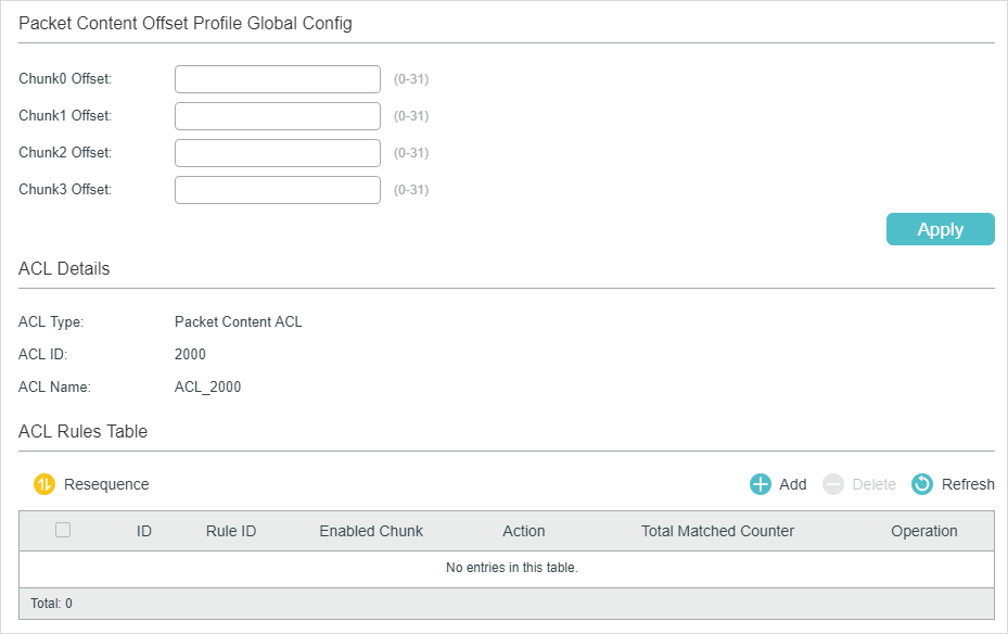
In the Packet Content Offset Profile Global Config section, configure the Chunk Offset. Click Apply.
|
Chunk0 Offset/Chunk1 Offset/Chunk2 Offset/Chunk3 Offset |
Enter the offset of a chunk. Packet Content ACL analyzes and processes data packets based on 4 chunk match conditions, and each chunk can specify a user-defined 4-byte segment carried in the packet’s first 128 bytes. Offset 31 matches the 127, 128, 1, 2 bytes of the packet, offset 0 matches the 3,4,5,6 bytes of the packet, and so on, for the rest of the offset value. Note: All 4 chunks must be set at the same time. |
In ACL Rules Table section, click and the following page will appear.
Figure 2-28 Configuring the Packet Content ACL Rule
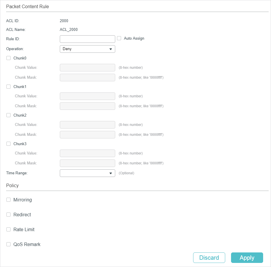
Follow these steps to configure the Packet Content ACL rule:
1)In the Packet Content Rule section, configure the following parameters:
|
Rule ID |
Enter an ID number to identify the rule. It should not be the same as any current rule ID in the same ACL. For the convenience of inserting new rules to an ACL, you should set the appropriate interval between rule IDs. If you select Auto Assign, the rule ID will be assigned automatically by the system and the default increment between neighboring rule IDs is 5 |
|
Operation |
Select an action to be taken when a packet matches the rule. Permit: To forward the matched packets. Deny: To discard the matched packets. |
|
Chunk0-Chunk3 |
Specify the EtherType to be matched using 4 hexadecimal numbers. |
|
Chunk Value |
Enter the 4-byte value in hexadecimal for the desired chunk, like ‘0000ffff’. The Packet Content ACL will check this chunk of packets to examine if the packets match the rule or not. |
|
Chunk Mask |
Enter the 4-byte mask in hexadecimal for the desired chunk. The mask must be written completely in 4-byte hex mode, like ‘0000ffff’. The mask specifies which bits to match the rule. |
|
Time Range |
Select a time range during which the rule will take effect. The default value is No Limit, which means the rule is always in effect. The Time Range referenced here can be created on the SYSTEM > Time Range page. |
|
Logging |
Enable Logging function for the ACL rule. Then the times that the rule is matched will be logged every 5 minutes and a related trap will be generated. You can refer to Total Matched Counter in the ACL Rules Table to view the matching times. |
2)In the Policy section, enable or disable the Mirroring feature for the matched packets. With this option enabled, choose a destination port to which the packets will be mirrored.
Figure 2-29 Configuring Mirroring
3)In the Policy section, enable or disable the Redirect feature for the matched packets. With this option enabled, choose a destination port to which the packets will be redirected.
Figure 2-30 Configuring Redirect
|
|
Note: In the Mirroring feature, the matched packets will be copied to the destination port and the original forwarding will not be affected. While in the Redirect feature, the matched packets will be forwarded only on the destination port. |
4)In the Policy section, enable or disable the Rate Limit feature for the matched packets. With this option enabled, configure the related parameters.
Figure 2-31 Configuring Rate Limit
|
Rate |
Specify the transmission rate for the matched packets. |
|
Burst Size |
Specify the maximum number of bytes allowed in one second. |
|
Out of Band |
Select the action for the packets whose rate is beyond the specified rate. None: The packets will be forwarded normally. Drop: The packets will be discarded. Remark DSCP: You can specify a DSCP value, and the DSCP field of the packets will be changed to the specified one. |
5)In the Policy section, enable or disable the QoS Remark feature for the matched packets. With this option enabled, configure the related parameters, and the remarked values will take effect in the QoS processing on the switch.
Figure 2-32 Configuring QoS Remark
|
DSCP |
Specify the DSCP field for the matched packets. The DSCP field of the packets will be changed to the specified one. |
|
Local Priority |
Specify the local priority for the matched packets. The local priority of the packets will be changed to the specified one. |
|
802.1p Priority |
Specify the 802.1p priority for the matched packets. The 802.1p priority of the packets will be changed to the specified one. |
6)Click Apply.
Viewing the ACL Rules
The rules in an ACL are listed in ascending order of their rule IDs. The switch matches a received packet with the rules in order. When a packet matches a rule, the switch stops the match process and performs the action defined in the rule.
Click Edit ACL for an entry you have created and you can view the rule table. We take IP ACL rules table for example.
Figure 2-33 Viewing ACL Rules Table
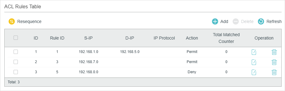
Here you can view and edit the ACL rules. You can also click Resequence to resequence the rules by providing a Start Rule ID and Step value.
2.1.4Configuring ACL Binding
You can bind the ACL to a port or a VLAN. The received packets on the port or in the VLAN will then be matched and processed according to the ACL rules. An ACL takes effect only after it is bound to a port or VLAN.
|
|
Note: Different types of ACLs cannot be bound to the same port or VLAN. Multiple ACLs of the same type can be bound to the same port or VLAN. The switch matches the received packets using the ACLs in order. The ACL that is bound earlier has a higher priority. |
Binding the ACL to a Port
Choose the menu SECURITY > ACL > ACL Binding > Port Binding and click to load the following page.
Figure 2-34 Binding the ACL to a Port
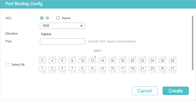
Follow these steps to bind the ACL to a Port:
1)Choose ID or Name to be used for matching the ACL. Then select an ACL from the drop-down list.
2)Specify the port to be bound.
3)Click Create.
Binding the ACL to a VLAN
Choose the menu SECURITY > ACL > ACL Binding > VLAN Binding to load the following page.
Figure 2-35 Binding the ACL to a VLAN
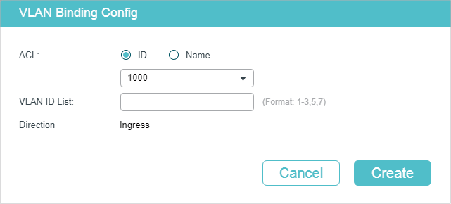
Follow these steps to bind the ACL to a VLAN:
1)Choose ID or Name to be used for matching the ACL. Then select an ACL from the drop-down list.
2)Enter the ID of the VLAN to be bound.
3)Click Create.
2.2Using the CLI
2.2.1Configuring Time Range
Some ACL-based services or features may need to be limited to take effect only during a specified time period. In this case, you can configure a time range for the ACL. For details about Time Range Configuration, please refer to Managing System.
2.2.2Configuring ACL
Follow the steps to create different types of ACL and configure the ACL rules.
You can define the rules based on source or destination IP address, source or destination MAC address, protocol type, port number and others.
MAC ACL
Follow these steps to configure MAC ACL:
|
Step 1 |
configure Enter global configuration mode. |
|
Step 2 |
access-list create acl-id [name acl-name] Create a MAC ACL. acl-id:Enter an ACL ID. The ID ranges from 0 to 499. acl-name: Enter a name to identify the ACL. |
|
Step 3 |
access-list mac acl-id-or-name rule { auto | rule-id } { deny | permit } logging {enable | disable} [ smac source-mac smask source-mac-mask ] [dmac destination-mac dmask destination-mac-mask ] [type ether-type] [pri dot1p-priority] [vid vlan-id] [tseg time-range-name] Add a MAC ACL Rule. acl-id-or-name: Enter the ID or name of the ACL that you want to add a rule for. auto: The rule ID will be assigned automatically and the interval between rule IDs is 5. rule-id: Assign an ID to the rule. deny | permit: Specify the action to be taken with the packets that match the rule. By default, it is set to permit. The packets will be discarded if “deny” is selected and forwarded if “permit” is selected. logging {enable | disable}: Enable or disable Logging function for the ACL rule. If "enable" is selected, the times that the rule is matched will be logged every 5 minutes. With ACL Counter trap enabled, a related trap will be generated if the matching times changes. source-mac: Enter the source MAC address. The format is FF:FF:FF:FF:FF:FF. source-mac-mask: Enter the mask of the source MAC address. This is required if a source MAC address is entered. The format is FF:FF:FF:FF:FF:FF. destination-mac: Enter the destination MAC address. The format is FF:FF:FF:FF:FF:FF. destination-mac-mask: Enter the mask of the destination MAC address. This is required if a destination MAC address is entered. The format is FF:FF:FF:FF:FF:FF. ether-type: Specify an Ethernet-type with 4 hexadecimal numbers. dot1p-priority: The user priority ranges from 0 to 7. The default is No Limit. vlan-id: The VLAN ID ranges from 1 to 4094. time-range-name: The name of the time-range. The default is No Limit. |
|
Step 4 |
exit Return to global configuration mode. |
|
Step 5 |
show access-list [ acl-id-or-name ] Display the current ACL configuration. acl-id-or-name: The ID number or name of the ACL. |
|
Step 6 |
end Return to privileged EXEC mode. |
|
Step 7 |
copy running-config startup-config Save the settings in the configuration file. |
The following example shows how to create MAC ACL 50 and configure Rule 5 to permit packets with source MAC address 00:34:A2:D4:34:B5:
Switch#configure
Switch(config)#access-list create 50
Switch(config-mac-acl)#access-list mac 50 rule 5 permit logging disable smac 00:34:A2:D4:34:B5 smask FF:FF:FF:FF:FF:FF
Switch(config-mac-acl)#exit
Switch(config)#show access-list 50
MAC access list 50 name: ACL_50
rule 5 permit logging disable smac 00:34:a2:d4:34:b5 smask ff:ff:ff:ff:ff:ff
Switch(config)#end
Switch#copy running-config startup-config
IP ACL
Follow these steps to configure IP ACL:
|
Step 1 |
configure Enter global configuration mode. |
|
Step 2 |
access-list create acl-id [name acl-name] Create an IP ACL. acl-id:Enter an ACL ID. The ID ranges from 500 to 999. acl-name: Enter a name to identify the ACL. |
|
Step 3 |
access-list ip acl-id-or-name rule {auto | rule-id } {deny | permit} logging {enable | disable} [sip sip-address sip-mask sip-address-mask ] [ dip dip-address dip-mask dip-address-mask ] [dscp dscp-value] [tos tos-value] [pre pre-value] [frag {enable | disable}] [protocol protocol [s-port s-port-number s-port-mask s-port-mask] [d-port d-port-number d-port-mask d-port-mask] [tcpflag tcpflag]] [tseg time-range-name] Add rules to the ACL. acl-id-or-name: Enter the ID or name of the ACL that you want to add a rule for. auto: The rule ID will be assigned automatically and the interval between rule IDs is 5. rule-id: Assign an ID to the rule. deny | permit: Specify the action to be taken with the packets that match the rule. Deny means to discard; permit means to forward. By default, it is set to permit. logging {enable | disable}: Enable or disable Logging function for the ACL rule. If "enable" is selected, the times that the rule is matched will be logged every 5 minutes. With ACL Counter trap enabled, a related trap will be generated if the matching times changes. sip-address: Enter the source IP address. sip-address-mask: Enter the mask of the source IP address. This is required if a source IP address is entered. dip-address: Enter the destination IP address. dip-address-mask: Enter the mask of the destination IP address. This is required if a destination IP address is entered. |
|
dscp-value: Specify the DSCP value between 0 and 63. tos-value: Specify an IP ToS value to be matched between 0 and 15. pre-value: Specify an IP Precedence value to be matched between 0 and 7. frag {enable | disable}: Enable or disable matching of fragmented packets. The default is disable. When enabled, the rule will apply to all fragmented packets and always permit to forward the last fragment of a packet. T1500 series, T1600G-18TS, T1600G-28TS, T1600G-28PS, T1600G-52TS v4 and T1600G-52PS v4 do not support this option. protocol: Specify a protocol number between 0 and 255. s-port-number: With TCP or UDP configured as the protocol, specify the source port number. s-port-mask: With TCP or UDP configured as the protocol, specify the source port mask with 4 hexadacimal numbers. d-port-number: With TCP or UDP configured as the protocol, specify the destination port number. d-port-mask: With TCP or UDP configured as the protocol, specify the destination port mask with 4 hexadacimal numbers. tcpflag: With TCP configured as the protocol, specify the flag value using either binary numbers or * (for example, 01*010*). The default is *, which indicates that the flag will not be matched. The flags are URG (Urgent flag), ACK (Acknowledge Flag), PSH (Push Flag), RST (Reset Flag), SYN (Synchronize Flag) and FIN (Finish Flag). time-range-name: The name of the time-range. The default is No Limit. |
|
|
Step 4 |
end Return to privileged EXEC mode. |
|
Step 5 |
copy running-config startup-config Save the settings in the configuration file. |
The following example shows how to create IP ACL 600, and configure Rule 1 to permit packets with source IP address 192.168.1.100:
Switch#configure
Switch(config)#access-list create 600
Switch(config)#access-list ip 600 rule 1 permit logging disable sip 192.168.1.100 sip-mask 255.255.255.255
Switch(config)#show access-list 600
IP access list 600 name: ACL_600
rule 1 permit logging disable sip 192.168.1.100 smask 255.255.255.255
Switch(config)#end
Switch#copy running-config startup-config
Combined ACL
Follow these steps to configure Combined ACL:
|
Step 1 |
configure Enter global configuration mode |
|
Step 2 |
access-list create acl-id [name acl-name] Create a Combined ACL. acl-id:Enter an ACL ID. The ID ranges from 1000 to 1499. acl-name: Enter a name to identify the ACL. |
|
Step 3 |
access-list combined acl-id-or-name rule {auto | rule-id } {deny | permit} logging {enable | disable} [smac source-mac-address smask source-mac-mask] [dmac dest-mac-address dmask dest-mac-mask] [vid vlan-id] [type ether-type] [pri priority] [sip sip-address sip-mask sip-address-mask] [dip dip-address dip-mask dip-address-mask] [dscp dscp-value] [tos tos-value] [pre pre-value] [protocol protocol [s-port s-port-number s-port-mask s-port-mask] [d-port d-port-number d-port-mask d-port-mask] [tcpflag tcpflag]] [tseg time-range-name] Add rules to the ACL. acl-id-or-name: Enter the ID or name of the ACL that you want to add a rule for. auto: The rule ID will be assigned automatically and the interval between rule IDs is 5. rule-id: Assign an ID to the rule. deny | permit: Specify the action to be taken with the packets that match the rule. Deny means to discard; permit means to forward. By default, it is set to permit. logging {enable | disable}: Enable or disable Logging function for the ACL rule. If "enable" is selected, the times that the rule is matched will be logged every 5 minutes. With ACL Counter trap enabled, a related trap will be generated if the matching times changes. source-mac-address: Enter the source MAC address. source-mac-mask: Enter the source MAC address mask. dest-mac-address: Enter the destination MAC address. dest-mac-mask: Enter the destination MAC address mask. This is required if a destination MAC address is entered. vlan-id: The VLAN ID ranges from 1 to 4094. ether-type: Specify the Ethernet-type with 4 hexadecimal numbers. priority: The user priority ranges from 0 to 7. The default is No Limit. sip-address: Enter the source IP address. sip-address-mask: Enter the mask of the source IP address. It is required if source IP address is entered. dip-address: This is required if a source IP address is entered. dip-address-mask: Enter the destination IP address mask. This is required if a destination IP address is entered. dscp-value: Specify the DSCP value between 0 and 63. tos-value: Specify an IP ToS value to be matched between 0 and 15. pre-value: Specify an IP Precedence value to be matched between 0 and 7. |
|
protocol: Specify a protocol number between 0 and 255. s-port-number: With TCP or UDP configured as the protocol, specify the source port number. s-port-mask: With TCP or UDP configured as the protocol, specify the source port mask with 4 hexadacimal numbers. d-port-number: With TCP or UDP configured as the protocol, specify the destination port number. d-port-mask: With TCP or UDP configured as the protocol, specify the destination port mask with 4 hexadacimal numbers. tcpflag: With TCP configured as the protocol, specify the flag value using either binary numbers or * (for example, 01*010*). The default is *, which indicates that the flag will not be matched. The flags are URG (Urgent flag), ACK (Acknowledge Flag), PSH (Push Flag), RST (Reset Flag), SYN (Synchronize Flag), and FIN (Finish Flag). time-range-name: The name of the time-range. The default is No Limit. |
|
|
Step 4 |
end Return to privileged EXEC mode. |
|
Step 5 |
copy running-config startup-config Save the settings in the configuration file. |
The following example shows how to create Combined ACL 1100 and configure Rule 1 to deny packets with source IP address 192.168.3.100 in VLAN 2:
Switch#configure
Switch(config)#access-list create 1100
Switch(config)#access-list combined 1100 logging disable rule 1 permit vid 2 sip 192.168.3.100 sip-mask 255.255.255.255
Switch(config)#show access-list 2600
Combined access list 2600 name: ACL_2600
rule 1 permit logging disable vid 2 sip 192.168.3.100 sip-mask 255.255.255.255
Switch(config)#end
Switch#copy running-config startup-config
IPv6 ACL
Follow these steps to configure IPv6 ACL:
|
Step 1 |
configure Enter global configuration mode |
|
Step 2 |
access-list create acl-id [name acl-name] Create an IPv6 ACL. acl-id:Enter an ACL ID. The ID ranges from 1500 to 1999. acl-name: Enter a name to identify the ACL. |
|
Step 3 |
access-list ipv6 acl-id-or-name rule {auto | rule-id } {deny | permit} logging {enable | disable} [class class-value] [flow-label flow-label-value] [sip source-ip-address sip-mask source-ip-mask ] [dip destination-ip-address dip-mask destination-ip-mask] [s-port source-port-number] [d-port destination-port-number] [tseg time-range-name] Add rules to the ACL. acl-id-or-name: Enter the ID or name of the ACL that you want to add a rule for. auto: The rule ID will be assigned automatically and the interval between rule IDs is 5. rule-id: Assign an ID to the rule. deny | permit: Specify the action to be taken with the packets that match the rule. Deny means to discard; permit means to forward. By default, it is set to permit. logging {enable | disable}: Enable or disable Logging function for the ACL rule. If "enable" is selected, the times that the rule is matched will be logged every 5 minutes. With ACL Counter trap enabled, a related trap will be generated if the matching times changes. class-value: Specify a class value to be matched. It ranges from 0 to 63. flow-label-value: Specify a Flow Label value to be matched. source-ip-address: Enter the source IP address. Enter the destination IPv6 address to be matched. All types of IPv6 address will be checked. You may enter a complete 128-bit IPv6 address but only the first 64 bits will be valid. source-ip-mask: Enter the source IP address mask. The mask is required if the source IPv6 address is entered. Enter the mask in complete format (for example, ffff:ffff:0000:ffff). The mask specifies which bits in the source IPv6 address to match the rule. destination-ip-address: Enter the destination IPv6 address to be matched. All types of IPv6 address will be checked. You may enter a complete 128-bit IPv6 addresses but only the first 64 bits will be valid. destination-ip-mask: Enter the source IP address mask. The mask is required if the source IPv6 address is entered. Enter the mask in complete format (for example, ffff:ffff:0000:ffff). The mask specifies which bits in the source IPv6 address to match the rule. source-port-number: Enter the TCP/UDP source port if TCP/UDP protocol is selected. destination-port-number: Enter the TCP/UDP destination port if TCP/UDP protocol is selected. time-range-name: The name of the time-range. The default is No Limit. |
|
Step 4 |
end Return to privileged EXEC mode. |
|
Step 5 |
copy running-config startup-config Save the settings in the configuration file. |
The following example shows how to create IPv6 ACL 1600 and configure Rule 1 to deny packets with source IPv6 address CDCD:910A:2222:5498:8475:1111:3900:2020:
Switch#configure
Switch(config)#access-list create 1600
Switch(config)#access-list ipv6 1600 rule 1 deny logging disable sip CDCD:910A:2222:5498:8475:1111:3900:2020 sip-mask ffff:ffff:ffff:ffff
Switch(config)#show access-list 1600
IPv6 access list 1600 name: ACL_1600
rule 1 deny logging disable sip cdcd:910a:2222:5498:8475:1111:3900:2020 sip-mask ffff:ff
ff:ffff:ffff
Switch(config)#end
Switch#copy running-config startup-config
Packet Content ACL
Only T2600G series support this feature.
Follow these steps to configure Packet Content ACL:
|
Step 1 |
configure Enter global configuration mode |
|
Step 2 |
access-list create acl-id [name acl-name] Create a Packet Content ACL. acl-id:Enter an ACL ID. The ID ranges from 2000 to 2499. acl-name: Enter a name to identify the ACL. |
|
Step 3 |
access-list packet-content profile chunk-offset0 offset0 chunk-offset1 offset1 chunk-offset2 offset2 chunk-offset3 offset3 Specify the offset of each chunk, all the 4 chunks must be set at the same time. offset0 -offset3: Specify the offset of each chunk, the value ranges from 0 to 31. When the offset is set as 31, it matches the first 127,128, 1, 2 bytes of the packet; when the offset is set as 0, it matches the 3, 4, 5, 6 bytes, and so on, for the rest of the offset value. |
|
Step 4 |
access-list packet-content config acl-id-or-name rule { auto | rule-id } {deny | permit} logging { enable | disable } [chunk0 value mask0 mask] [chunk1 value mask1 mask] [chunk2 value mask2 mask] [chunk3 value mask3 mask] [tseg time-range-name] Add rules to the ACL. acl-id-or-name: Enter the ID or name of the ACL that you want to add a rule for. auto: The rule ID will be assigned automatically and the interval between rule IDs is 5. rule-id: Assign an ID to the rule. deny | permit: Specify the action to be taken with the packets that match the rule. Deny means to discard; permit means to forward. By default, it is set to permit. logging { enable | disable} : Enable or disable Logging function for the ACL rule. If "enable" is selected, the times that the rule is matched will be logged every 5 minutes. With ACL Counter trap enabled, a related trap will be generated if the matching times changes. value: Enter the 4-byte value in hexadecimal for the desired chunk, like ‘0000ffff’. The Packet Content ACL will check this chunk of packets to examine if the packets match the rule or not. mask: Enter the 4-byte mask in hexadecimal for the desired chunk. The mask must be written completely in 4-byte hex mode, like ‘0000ffff’. The mask specifies which bits to match the rule. time-range-name: The name of the time-range. The default is No Limit. |
|
Step 5 |
end Return to privileged EXEC mode. |
|
Step 6 |
copy running-config startup-config Save the settings in the configuration file. |
The following example shows how to create Packet Content ACL 2000, and deny the packets with the value of its chunk1 0x58:
Switch#configure
Switch(config)#access-list create 2000
Switch(config)#access-list packet-content profile chunk-offset0 offset0 chunk-offset1 offset1 chunk-offset2 offset2 chunk-offset3 offset3
Switch(config)#packet-content config 2000 rule 10 deny logging disable chunk1 58 mask1 ffffffff
Switch(config)#show access-list 2000
Packet content access list 2000 name: ACL_2000
rule 10 deny logging disable chunk1 value 0x58 mask 0xffffffff
Switch(config)#end
Switch#copy running-config startup-config
Resequencing Rules
You can resequence the rules by providing a Start Z and Step value.
|
Step 1 |
configure Enter global configuration mode. |
|
Step 2 |
access-list resequence acl-id-or-name start start-rule-id step rule-id-step-value Resequence the rules of the specific ACL. acl-id-or-name: Enter the ID or name of the ACL. start-rule-id: Enter the start rule ID. rule-id-step-value: Enter the Step value. |
|
Step 3 |
end Return to privileged EXEC mode. |
|
Step 4 |
copy running-config startup-config Save the settings in the configuration file. |
The following example shows how to resequence the rules of MAC ACL 100: set the start rule ID as 1 and the step value as 10:
Switch#configure
Switch(config)#access-list resequence 100 start 1 step 10
Switch(config)#show access-list 100
MAC access list 100 name: “ACL_100”
rule 1 deny logging disable smac aa:bb:cc:dd:ee:ff smask ff:ff:ff:ff:ff:ff
rule 11 permit logging disable vid 18
rule 21 permit logging disable dmac aa:cc:ee:ff:dd:33 dmask ff:ff:ff:ff:ff:ff
Switch(config)#end
Switch#copy running-config startup-config
2.2.3Configuring Policy
Policy allows you to further process the matched packets through operations such as mirroring, rate-limiting, redirecting, or changing priority.
Follow the steps below to configure the policy actions for an ACL rule.
|
Step 1 |
configure Enter global configuration mode. |
|
Step 2 |
access-list action acl-id-or-name rule rule-id Configure the policy actions for an ACL rule. acl-id-or-name: Enter the ID or name of the ACL. rule-id: Enter the ID of the ACL rule. |
|
Step 3 |
redirect interface { fastEthernet port | gigabitEthernet port | ten-gigabitEthernet port } (Optional) Define the policy to redirect the matched packets to the desired port. port: The destination port to which the packets will be redirected. The default is All. s-mirror interface { fastEthernet port | gigabitEthernet port | ten-gigabitEthernet port } (Optional) Define the policy to mirror the matched packets to the desired port. port: The destination port to which the packets will be mirrored. s-condition rate rate burst burst-size osd { none | discard | remark dscp dscp } (Optional) Define the policy to monitor the rate of the matched packets. rate: Specify a rate from 1 to 1000000 kbps. burst-size: Specify the number of bytes allowed in one second ranging from 1 to 128. osd: Select either “none”, “discard” or “remark dscp” as the action to be taken for the packets whose rate is beyond the specified rate. The default is None. When “remark dscp” is selected, you also need to specify the DSCP value for the matched packets. The DSCP value ranges from 0 to 63. T1500 series, T1600G-18TS, T1600G-28TS, T1600G-28PS, T1600G-52TS v4 and T1600G-52PS v4 do not support DSCP option. qos-remark [dscp dscp] [ priority pri ] [ dot1p pri ] (Optional) Define the policy to remark priority for the matched packets. dscp: Specify the DSCP region for the data packets. The value ranges from 0 to 63. priority pri: Specify the local priority for the data packets. The value ranges from 0 to 7. dot1p pri: Specify the 802.1p priority for the data packets. The value ranges from 0 to 7. |
|
Step 4 |
end Return to privileged EXEC mode. |
|
Step 5 |
copy running-config startup-config Save the settings in the configuration file. |
Redirect the matched packets to port 1/0/4 for rule 1 of MAC ACL 10:
Switch#configure
Switch(config)#access-list action 10 rule 1
Switch(config-action)#redirect interface gigabitEthernet 1/0/4
Switch(config-action)#exit
Switch(config)#show access-list 10
MAC access list 10 name: ACL_10
rule 5 permit logging disable action redirect Gi1/0/4
Switch(config)#end
Switch#copy running-config startup-config
2.2.4Configuring ACL Binding
You can bind the ACL to a port or a VLAN. The received packets on the port or in the VLAN will then be matched and processed according to the ACL rules. An ACL takes effect only after it is bound to a port or VLAN.
|
|
Note: Different types of ACLs cannot be bound to the same port or VLAN. Multiple ACLs of the same type can be bound to the same port or VLAN. The switch matches the received packets using the ACLs in order. The ACL that is bound earlier has a higher priority. |

Follow the steps below to bind ACL to a port or a VLAN:
|
Step 1 |
configure Enter global configuration mode |
|
Step 2 |
access-list bind acl-id-or-name interface { [ vlan vlan-list ] | [ fastEthernet port-list ] | [ gigabitEthernet port-list ] | [ ten-gigabitEthernet port-list ] } Bind the ACL to a port or a VLAN. acl-id-or-name: Enter the ID or name of the ACL that you want to add a rule for. vlan-list: Specify the ID or the ID list of the VLAN(s) that you want to bind the ACL to. The valid values are from 1 to 4094, for example, 2-3,5. port-list: Specify the number or the list of the Ethernet port that you want to bind the ACL to. |
|
Step 3 |
show access-list bind View the ACL binding configuration. |
|
Step 4 |
end Return to privileged EXEC mode. |
|
Step 5 |
copy running-config startup-config Save the settings in the configuration file. |
The following example shows how to bind ACL 1 to port 3 and VLAN 4:
Switch#configure
Switch(config)#access-list bind 1 interface vlan 4 gigabitEthernet 1/0/3
SSwitch(config)#show access-list bind
ACL ID ACL NAME Interface/VID Direction Type
----- ---------- ------------- ------- ----
1 ACL_1 Gi1/0/3 Ingress Port
1 ACL_1 4 Ingress VLAN
Switch(config)#end
Switch#copy running-config startup-config
2.2.5Viewing ACL Counting
You can use the following command to view the number of matched packets of each ACL in the privileged EXEC mode and any other configuration mode:
|
show access-list acl-id-or-name counter View the number of matched packets of the specific ACL. acl-id-or-name: Specify the ID or name of the ACL to be viewed. |
3Configuration Example for ACL
3.1Configuration Example for MAC ACL
3.1.1Network Requirements
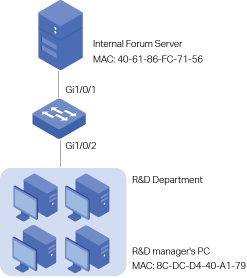
A company forbids the employees in the R&D department to visit the internal forum during work hours. While the manager of the R&D department can get access to the internal forum without limitation.
As shown below, the internal forum server is connected to the switch via port 1/0/1, and computers in the R&D department are connected to the switch via port 1/0/2.
Figure 3-1 Network Topology
3.1.2Configuration Scheme
To meet the requirements above, you can set up packet filtering by creating an MAC ACL and configuring rules for it.
Time Range Configuration
Create a time range entry for the work hour of the company. Apply the time range to the ACL rule which blocks the access to internal forum server.
ACL Configuration
Create a MAC ACL and configure the following rules for it:
Configure a permit rule to match packets with source MAC address 8C-DC-D4-40-A1-79 and destination MAC address 40-61-86-FC-71-56. This rule allows the manager of R&D department to visit internal forum at any time.
Configure a deny rule to match packets with destination MAC address 40-61-86-FC-71-56 and apply the time range of work hours. This rule forbids the employees in the R&D department to visit the internal forum during work hours.
Configure a permit rule to match all the packets that do not match neither of the above rules.
Binding Configuration
Bind the MAC ACL to port 1/0/2 so that the ACL rules will be applied to the computer of the devices in the R&D department which are restricted to the internal forum during work hours.
Demonstrated with T2600G-28TS, the following sections explain the configuration procedure in two ways: using the GUI and using the CLI.
3.1.3Using the GUI
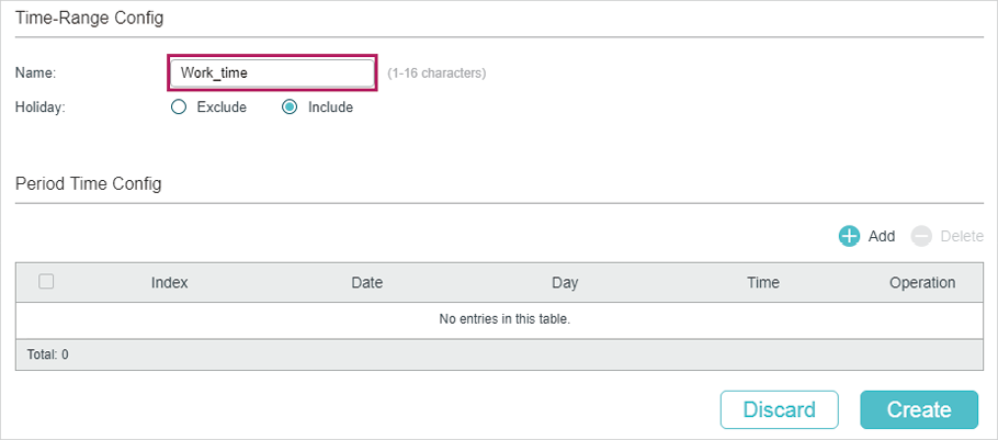
1)Choose the menu SYSTEM > Time Range > Time Range Config and click  to load the following page. Create a time range named Work_time.
Figure 3-2 Configuring Time Range
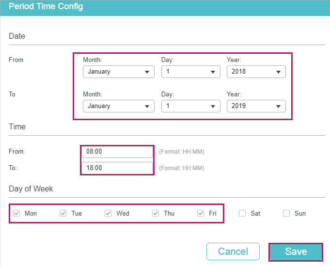
2)In the Period Time Config section, click  and the following window will pop up. Add the work hour of the company in the Period Time and click Save.
Figure 3-3 Adding Period Time
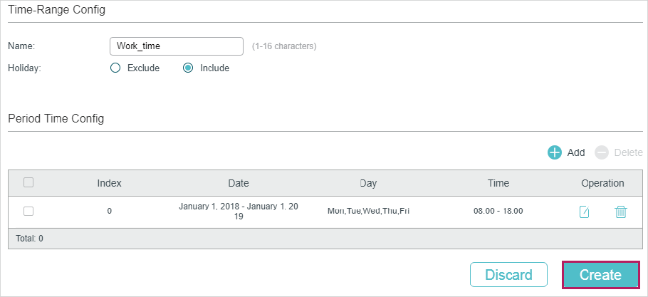
3)After adding the Period Time, click Create to save the time range entry.
Figure 3-4 Creating Time Range
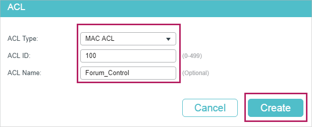
4)Choose the menu SECURITY > ACL > ACL Config and click to load the following page. Then create a MAC ACL for the marketing department.
Figure 3-5 Creating a MAC ACL
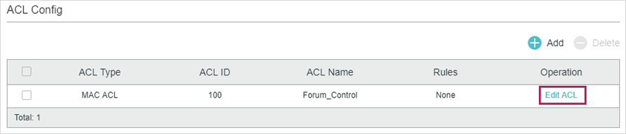
5)Click Edit ACL in the Operation column.
Figure 3-6 Editing the MAC ACL
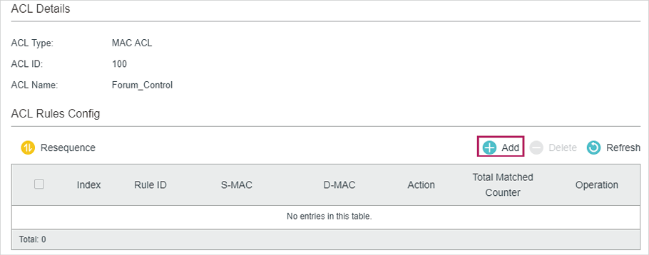
6)On the ACL configuration page, click  .
.
Figure 3-7 Editing the MAC ACL
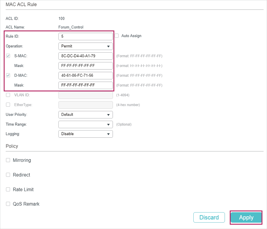
7)Configure rule 5 to permit packets with the source MAC address 8C-DC-D4-40-A1-79 and destination MAC address 40-61-86-FC-71-56.
Figure 3-8 Configuring Rule 5
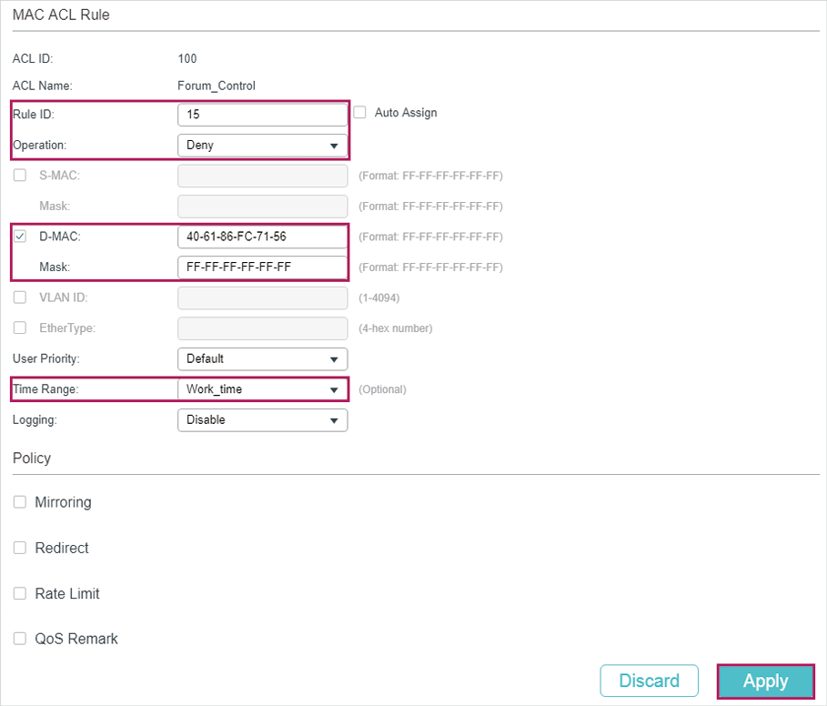
8)In the same way, configure rule 15 to deny packets with destination MAC address 40-61-86-FC-71-56 and apply the time range of work hours.
Figure 3-9 Configuring Rule 15
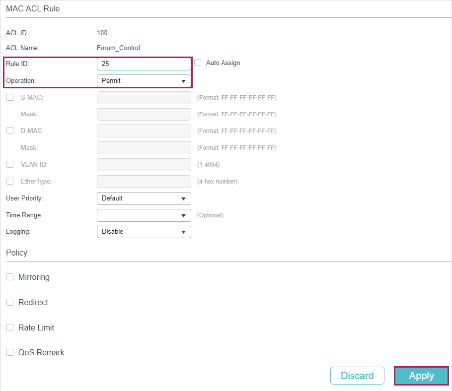
9)Configure rule 25 to permit all the packets that do not match neither of the above rules.
Figure 3-10 Configuring Rule 25
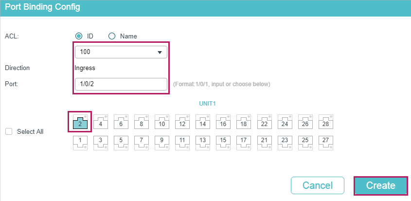
10)Choose the menu SECURITY > ACL > ACL Binding and click to load the following page. Bind ACL 100 to port 1/0/2 to make it take effect.
Figure 3-11 Binding the ACL to Port 1/0/2
11)Click  to save the settings.
3.1.4Using the CLI
1)Create a time range entry .
Switch#config
Switch(config)#time-range Work_time
Switch(config-time-range)#holiday include
Switch(config-time-range)#absolute from 01/01/2018 to 01/01/2019
Switch(config-time-range)#periodic start 08:00 end 18:00 day-of-the-week 1,2,3,4,5
Switch(config-time-range)#end
Switch#copy running-config startup-config
2)Create a MAC ACL.
Switch#configure
Switch(config)#access-list create 100 name Forum_Control
3)Configure rule 5 to permit packets with source MAC address 8C-DC-D4-40-A1-79 and destination MAC address 40-61-86-FC-71-56.
Switch(config)#access-list mac 100 rule 5 permit logging disable smac 8C:DC:D4:40:A1:79 smask FF: FF: FF: FF: FF: FF dmac 40:61:86:FC:71:56 dmask FF: FF: FF: FF: FF: FF
4)Configure rule 15 to deny packets with destination MAC address 40-61-86-FC-71-56.
Switch(config)#access-list mac 100 rule 15 deny logging disable dmac 40:61:86:FC:71:56 dmask FF: FF: FF: FF: FF: FF tseg Work_time
5)Configure rule 25 to permit all the packets. The rule makes sure that the traffic to other network resources will not be blocked by the switch.
Switch(config)#access-list mac 100 rule 25 permit logging disable
6)Bind ACL100 to port 1/0/2.
Switch(config)#access-list bind 100 interface gigabitEthernet 1/0/2
Switch(config)#end
Switch#copy running-config startup-config
Verify the Configurations
Verify the MAC ACL 100:
Switch#show access-list 100
MAC access list 100 name: “Forum_Control”
rule 5 permit logging disable smac 8c:dc:d4:40:a1:79 smask ff:ff:ff:ff:ff:ff dmac 40:61:86:fc:71:56 dmask ff:ff:ff:ff:ff:ff
rule 15 deny logging disable dmac 40:61:86:fc:71:56 dmask ff:ff:ff:ff:ff:ff tseg “Work_time”
rule 25 permit logging disable
Switch#show access-list bind
ACL ID ACL NAME Interface/VID Direction Type
------ -------- ------------- -------- ----
100 Forum_Control Gi1/0/2 Ingress Port
3.2Configuration Example for IP ACL
3.2.1Network Requirements
As shown below, a company’s internal server group can provide different types of services. Computers in the Marketing department are connected to the switch via port 1/0/1, and the internal server group is connected to the switch via port 1/0/2.
Figure 3-12 Network Topology
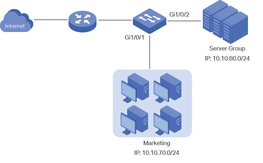
It is required that:
The Marketing department can only access internal server group in the intranet.
The Marketing department can only visit http and https websites on the internet.
3.2.2Configuration Scheme
To meet the requirements above, you can set up packet filtering by creating an IP ACL and configuring rules for it.
ACL Configuration
Create an IP ACL and configure the following rules for it:
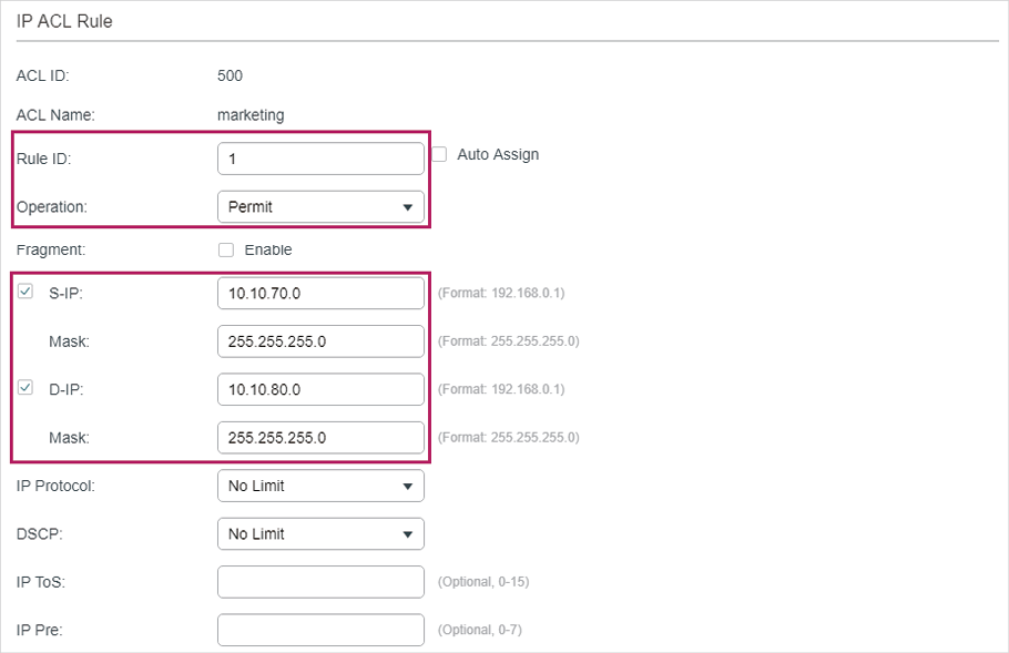
Configure a permit rule to match packets with source IP address 10.10.70.0/24, and destination IP address 10.10.80.0/24. This rule allows the Marketing department to access internal network servers from intranet.
Configure four permit rules to match the packets with source IP address 10.10.70.0/24, and destination ports TCP 80, TCP 443 and TCP/UDP 53. These allow the Marketing department to visit http and https websites on the internet.
Configure a deny rule to match the packets with source IP address 10.10.70.0/24. This rule blocks other network services.
The switch matches the packets with the rules in order, starting with Rule 1. If a packet matches a rule, the switch stops the matching process and initiates the action defined in the rule.
Binding Configuration
Bind the IP ACL to port 1/0/1 so that the ACL rules will apply to the Marketing department only.
Demonstrated with T2600G-28TS, the following sections explain the configuration procedure in two ways: using the GUI and using the CLI.
3.2.3Using the GUI
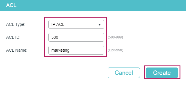
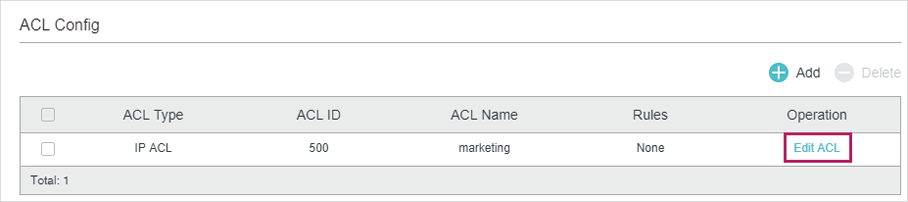
1)Choose the menu SECURITY > ACL > ACL Config and click to load the following page. Then create an IP ACL for the marketing department.
Figure 3-13 Creating an IP ACL
2)Click Edit ACL in the Operation column.
Figure 3-14 Editing IP ACL
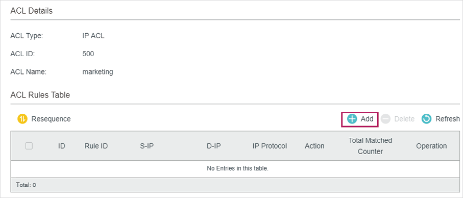
3)On the ACL configuration page, click .
Figure 3-15 Editing IP AC
4)Configure rule 1 to permit packets with the source IP address 10.10.70.0/24 and destination IP address 10.10.80.0/24.
Figure 3-16 Configuring Rule 1
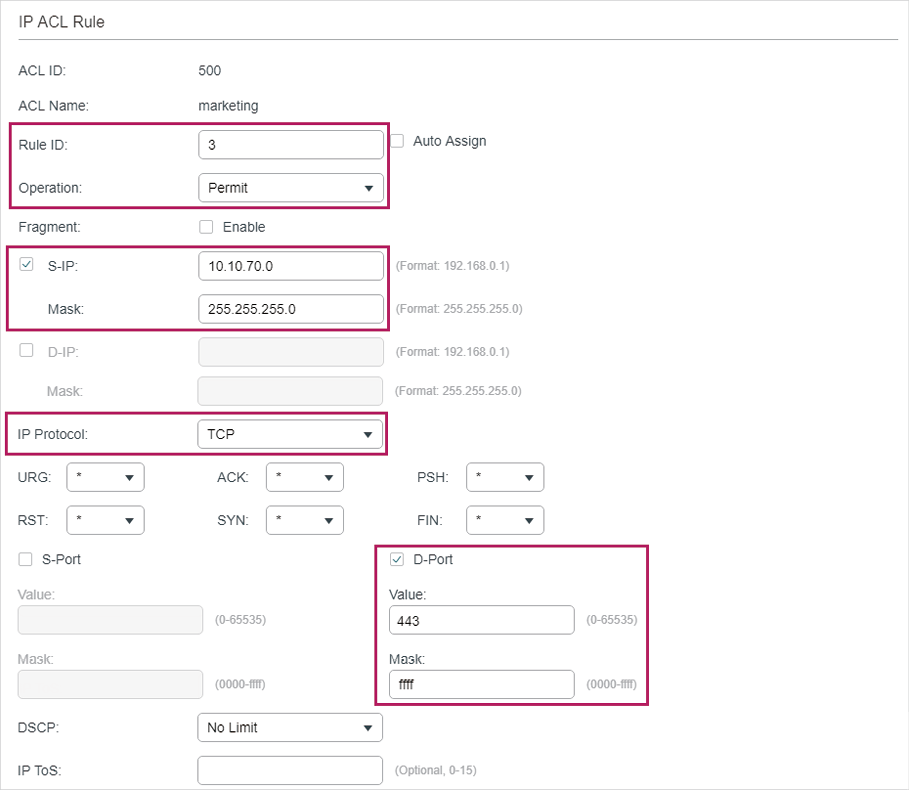
5)In the same way, configure rule 2 and rule 3 to permit packets with source IP 10.10.70.0 and destination port TCP 80 (http service port) and TCP 443 (https service port).
Figure 3-17 Configuring Rule 2
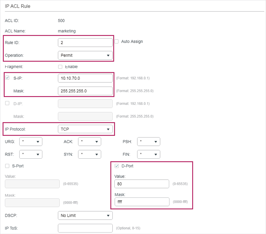
Figure 3-18 Configuring Rule 3
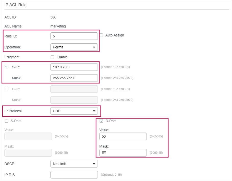
6)In the same way, configure rule 4 and rule 5 to permit packets with source IP 10.10.70.0 and with destination port TCP 53 or UDP 53 (DNS service port).
Figure 3-19 Configuring Rule 4
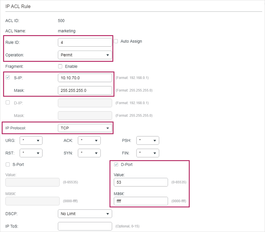
Figure 3-20 Configuring Rule 5
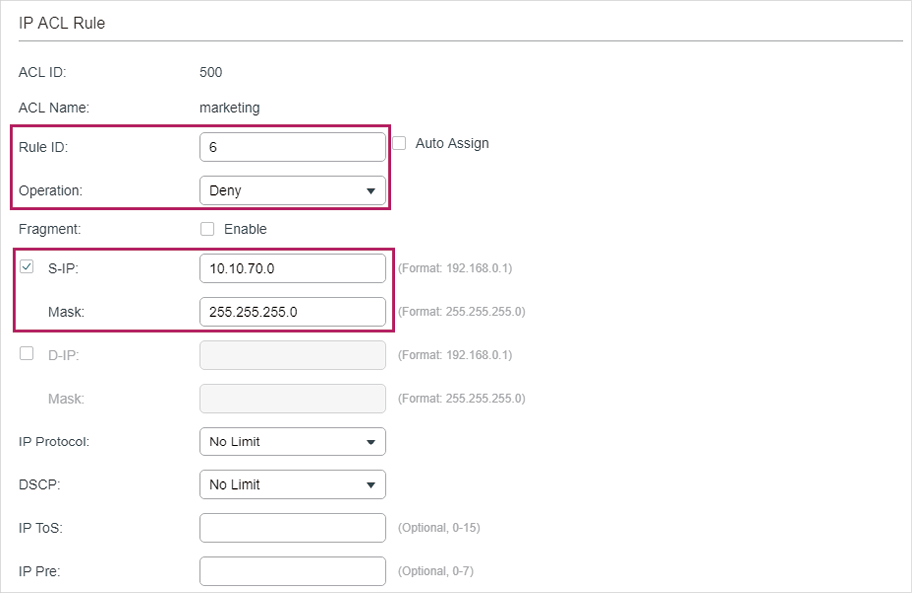
7)In the same way, configure rule 6 to deny packets with source IP 10.10.70.0.
Figure 3-21 Configuring Rule 6
8)Choose the menu SECURITY > ACL > ACL Binding and click to load the following page. Bind ACL Marketing to port 1/0/1 to make it take effect.
Figure 3-22 Binding the ACL to Port 1/0/1
9)Click  to save the settings.
3.2.4Using the CLI
1)Create an IP ACL.
Switch#configure
Switch(config)#access-list create 500 name marketing
2)Configure rule 1 to permit packets with source IP 10.10.70.0/24 and destination IP 10.10.80.0/24.
Switch(config)#access-list ip 500 rule 1 permit logging disable sip 10.10.70.0 sip-mask 255.255.255.0 dip 10.10.80.0 dmask 255.255.255.0
3)Configure rule 2 and Rule 3 to permit packets with source IP 10.10.70.0/24, and destination port TCP 80 (http service port) or TCP 443 (https service port).
Switch(config)#access-list ip 500 rule 2 permit logging disable sip 10.10.70.0 sip-mask 255.255.255.0 protocol 6 d-port 80 d-port-mask ffff
Switch(config)#access-list ip 500 rule 3 permit logging disable sip 10.10.70.0 sip-mask 255.255.255.0 protocol 6 d-port 443 d-port-mask ffff
4)Configure rule 4 and rule 5 to permit packets with source IP 10.10.70.0/24, and destination port TCP53 or UDP 53.
Switch(config)#access-list ip 500 rule 4 permit logging disable sip 10.10.70.0 sip-mask 255.255.255.0 protocol 6 d-port 53 d-port-mask ffff
Switch(config)#access-list ip 500 rule 5 permit logging disable sip 10.10.70.0 sip-amask 255.255.255.0 protocol 17 d-port 53 d-port-mask ffff
5)Configure rule 6 to deny packets with source IP 10.10.70.0/24.
Switch(config)#access-list ip 500 rule 2 deny logging disable sip 10.10.70.0 sip-mask 255.255.255.0
6)Bind ACL500 to port 1.
Switch(config)#access-list bind 500 interface gigabitEthernet 1/0/1
Switch(config)#end
Switch#copy running-config startup-config
Verify the Configurations
Verify the IP ACL 500:
Switch#show access-list 500
rule 1 permit logging disable sip 10.10.70.0 smask 255.255.255.0 dip 10.10.80.0 dmask 255.255.255.0
rule 2 permit logging disable sip 10.10.70.0 smask 255.255.255.0 protocol 6 d-port 80
rule 3 permit logging disable sip 10.10.70.0 smask 255.255.255.0 protocol 6 d-port 443
rule 4 permit logging disable sip 10.10.70.0 smask 255.255.255.0 protocol 6 d-port 53
rule 5 permit logging disable sip 10.10.70.0 smask 255.255.255.0 protocol 17 d-port 53
rule 6 deny loggin disable sip 10.10.70.0 smask 255.255.255.0
Switch#show access-list bind
ACL ID ACL NAME Interface/VID Direction Type
------ -------- ------------- -------- ----
500 marketing Gi1/0/1 Ingress Port
3.3Configuration Example for Combined ACL
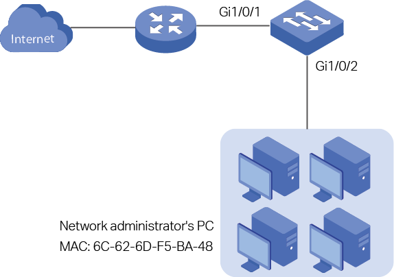
3.3.1Network Requirements
To enhance network security, a company requires that only the network administrator can log in to the switch through Telnet connection. The computers are connected to the switch via port 1/0/2. The network topology is shown as below.
Figure 3-23 Network Topology
3.3.2Configuration Scheme
To meet the requirements above, you can set up packet filtering by creating a Combined ACL and configuring rules for it.
ACL Configuration
Create a Combined ACL and configure the following rules for it:
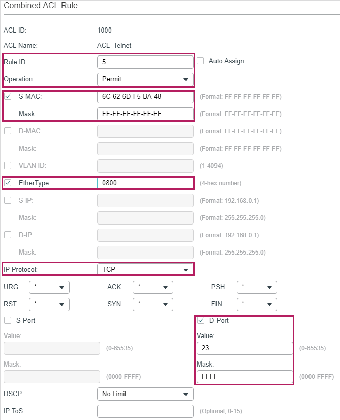
Configure a permit rule to match packets with source MAC address 6C-62-6D-F5-BA-48, and destination port TCP 23. This rule allows the computer of the network administrator to access the switch through Telnet connection.
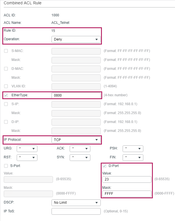
Configure a deny rule to match all the packets except the packets with source MAC address 6C-62-6D-F5-BA-48 and destination port TCP 23. This rule blocks the Telnet connection to the switch of other computers.
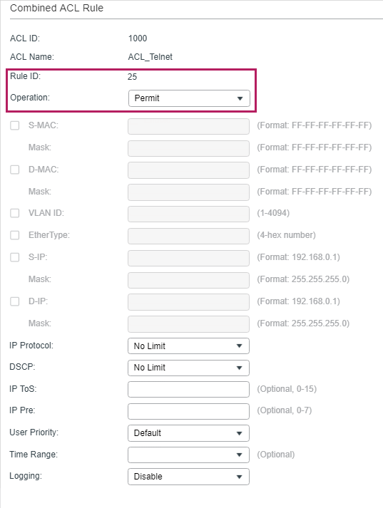
Configure a permit rule to match all the packets. This rule allows that other devices are given the network services except Telnet connection.
The switch matches the packets with the rules in order, starting with Rule 1. If a packet matches a rule, the switch stops the matching process and initiates the action defined in the rule.
Binding Configuration
Bind the Combined ACL to port 1/0/2 so that the ACL rules will be applied to the computer of the network administrator and the devices which are restricted to Telnet connection.
Demonstrated with T2600G-28TS, the following sections explain the configuration procedure in two ways: using the GUI and using the CLI.
3.3.3Using the GUI
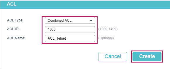
1)Choose the menu SECURITY > ACL > ACL Config and click to load the following page. Then create a Combined ACL for the marketing department.
Figure 3-24 Creating an Combined ACL
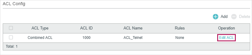
2)Click Edit ACL in the Operation column.
Figure 3-25 Editing Combined ACL
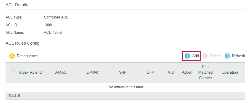
3)On the ACL configuration page, click .
Figure 3-26 Editing Combined ACL
4)Configure rule 5 to permit packets with the source MAC address 6C-62-6D-F5-BA-48 and destination port TCP 23 (Telnet service port).
Figure 3-27 Configuring Rule 5
5)Configure rule 15 to deny all the packets except the packet with source MAC address 6C-62-6D-F5-BA-48, and destination port TCP 23 (Telnet service port).
Figure 3-28 Configuring Rule 15
6)In the same way, configure rule 25 to permit all the packets. The rule makes sure that all devices can get other network services normally.
Figure 3-29 Configuring Rule 25
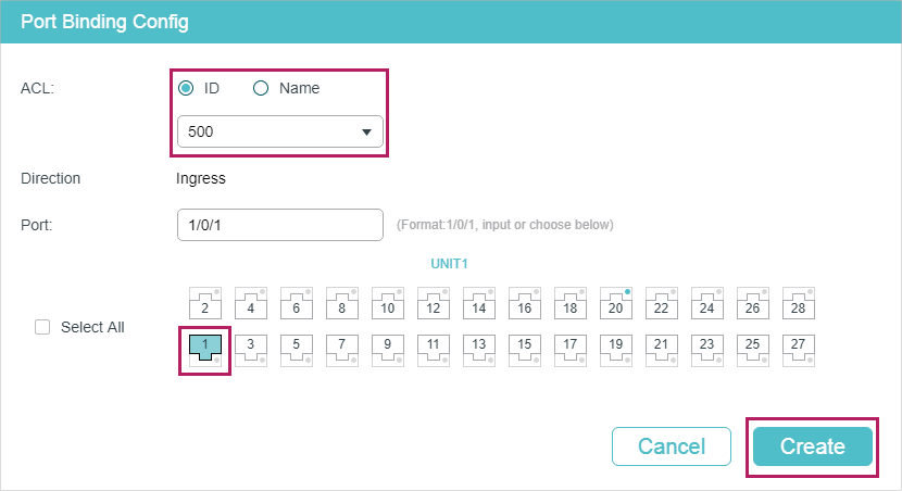
7)Choose the menu SECURITY > ACL > ACL Binding and click to load the following page. Bind the Policy ACL_Telnet to port 1/0/2 to make it take effect.
Figure 3-30 Binding the ACL to Port 1/0/2
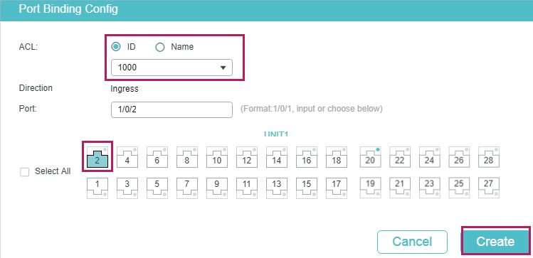
8)Click to save the settings.
3.3.4Using the CLI
1)Create a Combined ACL.
Switch#configure
Switch(config)#access-list create 1000 name ACL_Telnet
2)Configure rule 5 to permit packets with the source MAC address 6C-62-6D-F5-BA-48 and destination port TCP 23 (Telnet service port).
Switch(config)#access-list combined 1000 rule 5 permit logging disable smac 6C:62:6D:F5:BA: 48 smask FF: FF: FF: FF: FF: FF type 0800 protocol 6 d-port 23 d-port-mask FFFF
3)Configure rule 15 to deny all the packets except the packet with source MAC address 6C-62-6D-F5-BA-48, and destination port TCP 23 (Telnet service port).
Switch(config)#access-list combined 1000 rule 15 deny logging disable type 0800 protocol 6 d-port 23 d-port-mask FFFF
4)Configure rule 25 to permit all the packets. The rule makes sure that all devices can get other network services normally.
Switch(config)#access-list combined 1000 rule 25 permit logging disable type 0800 protocol 6 d-port 23 d-port-mask FFFF
5)Bind ACL500 to port 1/0/2.
Switch(config)#access-list bind 500 interface gigabitEthernet 1/0/2
Switch(config)#end
Switch#copy running-config startup-config
Verify the Configurations
Verify the Combined ACL 1000:
Switch#show access-list 1000
Combined access list 1000 name: “ACL_Telnet”
rule 5 permit logging disable smac 6c:62:6d:f5:ba:48 smask ff:ff:ff:ff:ff:ff type 0800 protocol 6 d-port 23
rule 15 deny logging disable type 0800 protocol 6 d-port 23
rule 25 permit logging disable
Switch#show access-list bind
ACL ID ACL NAME Interface/VID Direction Type
------ ----------------- ------------- -------- ----
1000 ACL_Telnet Gi1/0/2 Ingress Port
The default settings of ACL are listed in the following tables:
Table 4-1MAC ACL
|
Parameter |
Default Setting |
|
Operation |
Permit |
|
User Priority |
No Limit |
|
Time-Range |
No Limit |
Table 4-2IP ACL
|
Parameter |
Default Setting |
|
Operation |
Permit |
|
IP Protocol |
All |
|
DSCP |
No Limit |
|
IP ToS |
No Limit |
|
IP Pre |
No Limit |
|
Time-Range |
No Limit |
Table 4-3IPv6 ACL
|
Parameter |
Default Setting |
|
Operation |
Permit |
|
Time-Range |
No Limit |
Table 4-4Combined ACL
|
Parameter |
Default Setting |
|
Operation |
Permit |
|
Time-Range |
No Limit |
Table 4-5Packet Content ACL
|
Parameter |
Default Setting |
|
Operation |
Permit |
|
Time-Range |
No Limit |
Table 4-6Policy
|
Parameter |
Default Setting |
|
Mirroring |
Disabled |
|
Redirect |
Disabled |
|
Rate Limit |
Disabled |
|
QoS Remark |
Disabled |