Configuring Access Control In Multiple SSIDs
CHAPTERS
2. Configuring Access Control in Multiple SSIDs
|
|
This guide applies to: EAP Controller. |

In enterprise wireless networks, users may have a range of different requirements. For security reasons, it’s important to limit access to the EAP Controller to only the users who have the given authority. Access Control can provide this. The figure below shows the network topology of such a scenario. The administrator can divide users into two groups; users in Group 1 can access both the internet and the EAP Controller, while users in Group 2 can only access the internet.
Figure 1-1 Network topology for access control in Multiple SSIDs
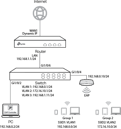
To achieve this, the administrator can configure two SSIDs in two different subnets and VLANs on the network. Different access control strategies can then be applied to the two SSIDs. The administrator can assign different SSIDs to different groups of users. The configuration follows the methodology below:
1)Configure WAN IP, LAN IP, and multi-nets NAT on the router, and static routing on both the router and the switch to ensure the network connectivity.
2)Configure two SSIDs in two different VLANs on the EAP Controller. Then assign each SSID to the corresponding user group.
3)Configure VLAN, interface IP and DHCP server on the switch. The switch will assign different IP addresses to clients connected to different SSIDs for all subnets.
4)Configure the hotspot portal and vouchers on the EAP Controller, so that the authenticated users can access the internet.
5)Configure access control strategy on the switch, so that only the users who have the given authority can access the EAP Controller.
2Configuring Access Control in Multiple SSIDs
This chapter explains how to configure access control in multiple SSIDs. The configuration consists of two parts:
1)Configuring the basics.
2)Configuring ACL.
2.1Configuring the Basics
To complete the basic network configuration, follow these steps:
1)Configure the router.
2)Configure the switch.
3)Configure the EAP Controller.
2.1.1Configuring the Router
Exampled with TL-ER6120, the configuration steps are as follows:
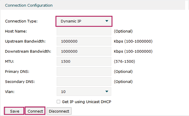
1)Choose the menu Network > WAN > WAN1 to load the following page. Specify the connection type according to your actual network environment. Here, we select Dynamic IP as the connection type. Click Save and Connect.
Figure 2-1 Configure WAN Port
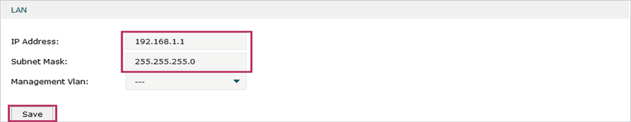
2)Choose the menu Network > LAN > LAN to load the following page. Specify the IP address as 192.168.1.1 and the subnet mask as 255.255.255.0. Click Save.
Figure 2-2 Configure LAN Port
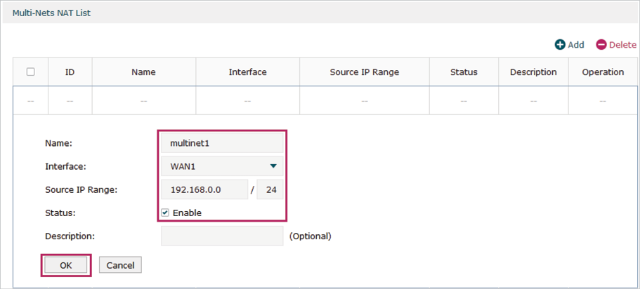
3)Choose the menu Transmission > NAT > Multi-Nets NAT and click Add to load the following page. Specify the name. Here, we specify the name as multinet1 for example. Select WAN1 as the interface. Specify the source IP range as 192.168.0.0/24. Check Enable for status. Click OK.
Figure 2-3 Configure Multi-Nets NAT 1
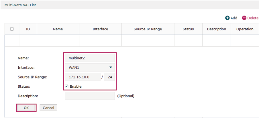
Similarly, add another entry as the following figure shows.
Figure 2-4 Configure Multi-Nets NAT 2
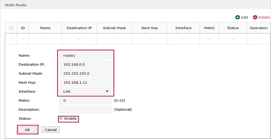
4)Choose the menu Transmission > Routing > Static Route and click Add to load the following page. Specify the name. Here, we specify the name as route1 for example. Specify the destination IP as 192.168.0.0 and subnet mask as 255.255.255.0. Specify the next hop as 192.168.1.11. Select LAN as the interface. Check Enable for status. Click OK.
Figure 2-5 Configure Static Route 1
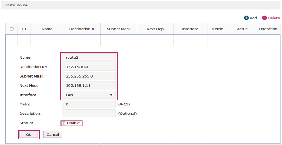
Similarly, add another entry as the following figure shows.
Figure 2-6 Configure Static Route 2
2.1.2Configuring the Switch
Exampled with T2600G-28TS, the configuration steps are as follows:
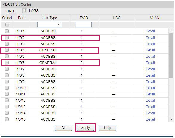
1)Choose the menu VLAN > 802.1Q VLAN > Port Config to load the following page. Specify the link type as ACCESS and PVID as 1 for port 1/0/2, and click Apply. Specify the link type as GENERAL and PVID as 1 for port 1/0/4, and click Apply. Specify the link type as GENERAL and PVID as 3 for port 1/0/6, and click Apply.
Figure 2-7 Configure Link Type and PVID for the Ports
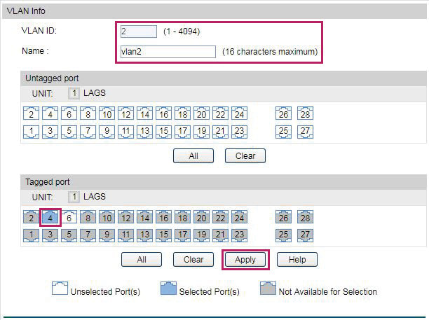
2)Choose the menu VLAN > 802.1Q VLAN > VLAN Config and click Create to load the following page. Specify the VLAN ID as 2. Specify the name as vlan2. Add 1/0/4 to VLAN 2 as tagged port, and click Apply.
Figure 2-8 Configure VLAN 2
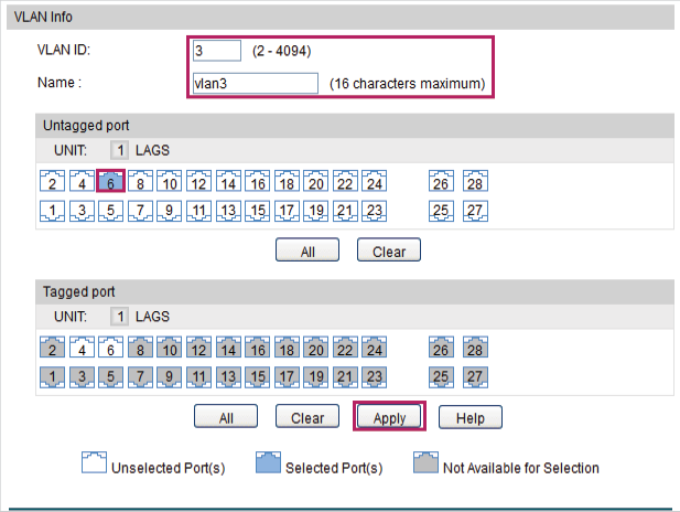
Similarly, configure another two VLANs as the following figures show.
Figure 2-9 Configure VLAN 1
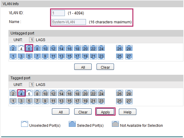
Figure 2-10 Configure VLAN 3
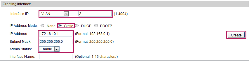
3)Choose the menu Routing > Interface > Interface Config to load the following page. Specify the interface ID as VLAN and set the VLAN ID as 2. Specify the IP address mode as Static. Specify the IP address as 172.16.10.1, and the subnet mask as 255.255.255.0. Enable the admin status. Click Create.
Figure 2-11 Create Interface VLAN 2
Similarly, configure another two interfaces as the following figures show.
Figure 2-12 Configure Interface VLAN 1
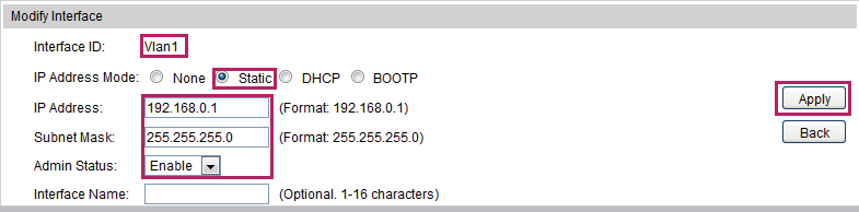
Figure 2-13 Creating Interface VLAN 3

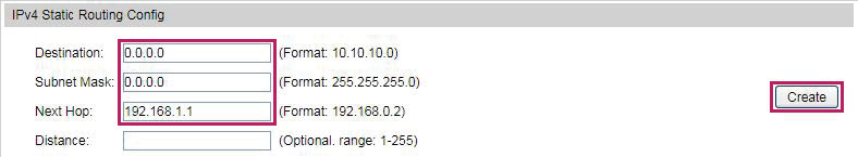
4)Choose the menu Routing > Static Routing > IPv4 Static Routing Config to load the following page. Specify the destination IP and subnet mask as 0.0.0.0, which means all the traffic. Specify the next hop as 192.168.1.1. Click Create.
Figure 2-14 Configure Static Route for All the Traffic
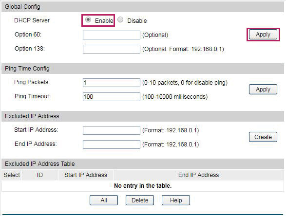
5)Choose the menu Routing > DHCP Server > DHCP Server to load the following page. In the Global Config section, enable the DHCP server and click Apply.
Figure 2-15 Enable DHCP Server
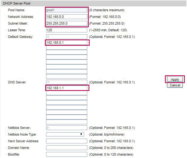
6)Choose the menu Routing > DHCP Server > Pool Setting to load the following page. Specify the pool name. Here, we specify the pool name as pool1 for example. Specify the network address as 192.168.0.0 and the subnet mask as 255.255.255.0. Specify the default gateway as 192.168.0.1. Specify the DNS server as 192.168.1.1. Click Apply.
Figure 2-16 Configure DHCP Server Pool 1
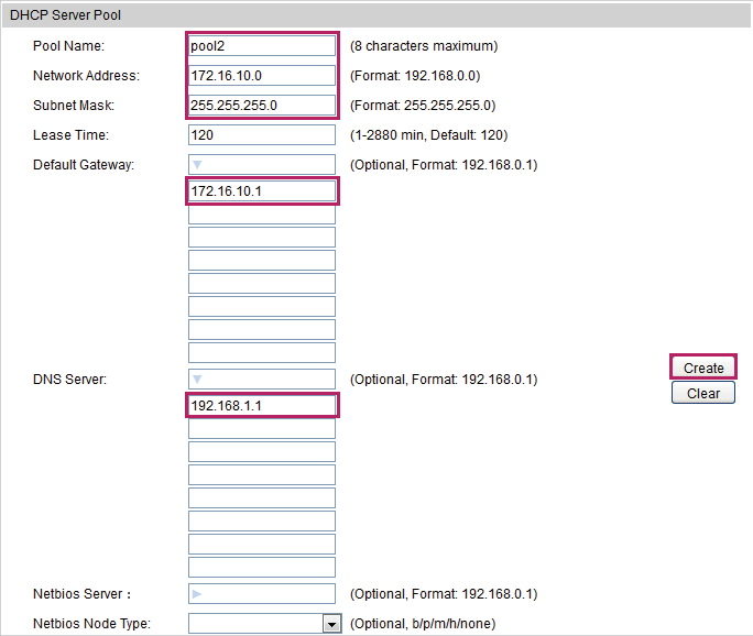
Similarly, add another DHCP server pool as the following figure shows.
Figure 2-17 Configure DHCP Server Pool 2
2.1.3Configuring the EAP Controller
The EAP can be managed by the EAP Contoller, which can be downloaded on the website:
https://www.tp-link.com/en/download/EAP-Controller.html.
Follow these steps to configure the EAP Controller:
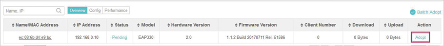
1)Run the EAP Controller and the management web page will pop up automatically. Choose the menu Access Points > Pending to load the following page. Click Adopt to adopt the EAP.
Figure 2-18 Adopt the EAP
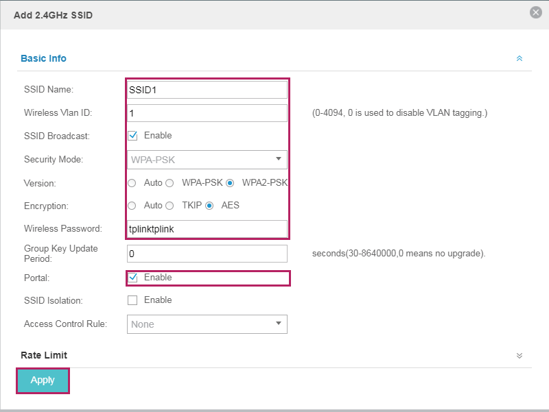
2)Choose the menu Wilreless Settings > Basic Wireless Setting, choose 2.4GHz or 5GHz, and click Add to load the following page. Specify the SSID name as SSID1. Specify the wireless VLAN ID as 1. Enable SSID broadcast. Specify the security mode as WPA-PSK. Specify the version as WPA2-PSK, and encryption as AES. Configure the wireless password for the SSID. Enable the portal. Click Apply.
Figure 2-19 Add SSID1
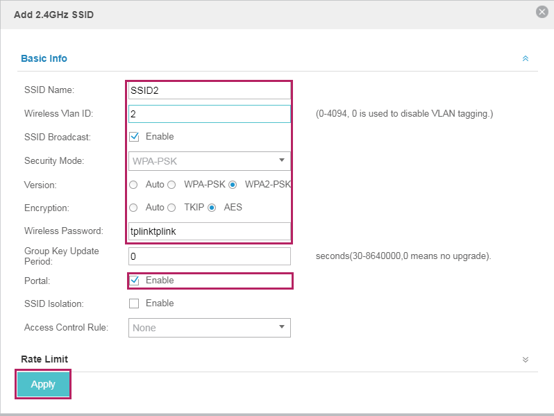
Similarly, add another SSID as the following figure shows.
Figure 2-20 Add SSID2
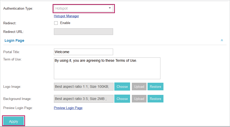
3)Choose the menu Wireless Control > Portal to load the following page. Specify the authentication type as Hotspot. Click Apply.
Figure 2-21 Configure the Portal
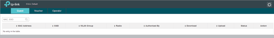
4)Choose the menu Wireless Control > Portal and click Hotspot Manager to load the following page.
Figure 2-22 Launch the Hotspot Manager
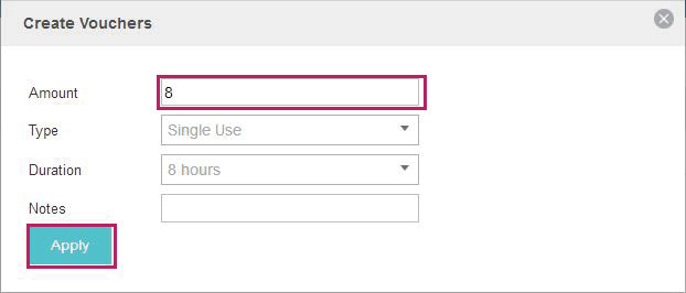
5)Choose the menu Voucher and click Create Vouchers to load the following page. Specify the amount of the vouchers according to your needs. Click Apply.
Figure 2-23 Create Vouchers
2.2Configuring ACL
After the basic network configuration, all the users in the two SSIDs can access the EAP controller and manage the EAP, which causes network security problems. To ensure only the users in Group 1 can access and manage the EAP Controller, configure the ACL (Access Control List) function on the switch. Follow these steps to configure the ACL function on the switch.
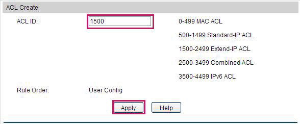
1)Choose the menu ACL > ACL Config > ACL Create to load the following page. Specify the ACL ID in the range of extended-IP ACL. Here, we specify the ACL ID as 1500 for example. Click Apply.
Figure 2-24 Create ACL
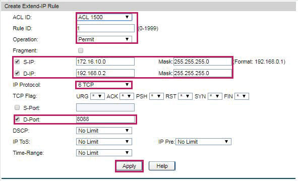
2)Choose the menu ACL > ACL Config > Extend-IP ACL to load the following page. Select ACL 1500 as the ACL ID. Specify the rule ID as 1. Select Permit as the operation. Enable S-IP and specify the S-IP as 172.16.10.0 and the mask as 255.255.255.0. Enable D-IP and specify the D-IP as 192.168.0.2 and the mask as 255.255.255.0. Note that the D-IP should be the IP address of the EAP Controller. Select 6 TCP as the IP protocol. Enable D-Port and specify the D-Port as 8088, which serves for the portal on the EAP Controller. Click Apply.
Figure 2-25 Create Extend-IP Rule 1
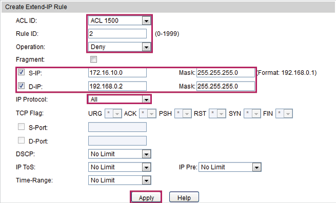
3)Choose the menu ACL > ACL Config > Extend-IP ACL to load the following page. Select ACL 1500 as the ACL ID. Specify the rule ID as 2. Select Deny as the operation. Enable S-IP and specify the S-IP as 172.16.10.0 and the mask as 255.255.255.0. Enable D-IP and specify the D-IP as 192.168.0.2 and the mask as 255.255.255.0. Note that the D-IP should be the IP address of the EAP Controller. Select All as the IP protocol. Click Apply.
Figure 2-26 Create Extend-IP Rule 2
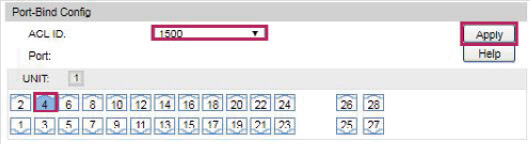
4)Choose the menu ACL > ACL Binding >Port Binding to load the following page. Select 1500 as the ACL ID and bind the ACL with port 1/0/4, which is connected to the EAP Controller. Click Apply.
Figure 2-27 Bind ACL to the Port
After all parts of the configuration are complete, you can test whether access control in multiple SSIDs works normally. Follow these steps to test access control in multiple SSIDs:
1)Test SSID1.
2)Test SSID2.
3.1Testing SSID1
Follow these steps to test SSID1:
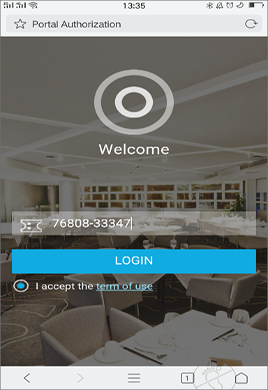
1)Connect your smart phone to SSID1. A portal will pop up. If it doesn’t, please go to http://www.tp-link.com to open the portal in a browser. It will look like this:
Figure 3-1 Launch the Portal Page
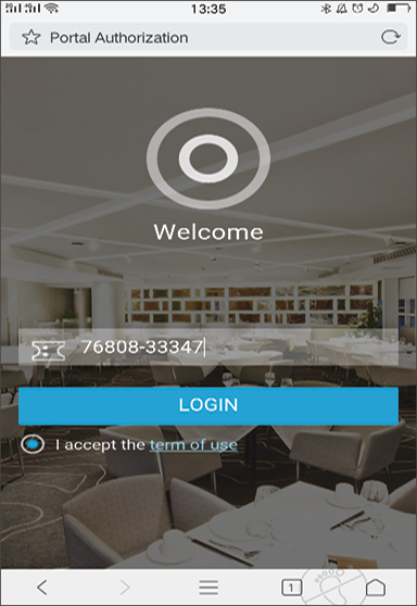
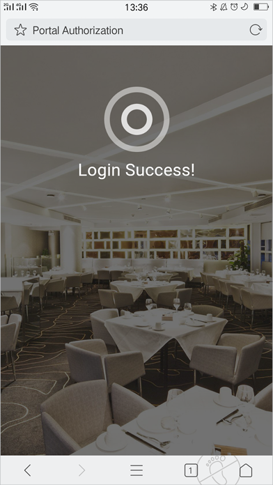
2)Enter a valid voucher code and click LOGIN. When the following page is displayed, you can access the internet after connecting to SSID1.
Figure 3-2 Log in
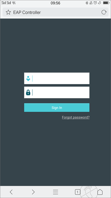
3)Enter https://192.168.0.2:8043 in the address bar of your browser to load the following page. Note that you should enter “https” instead of “http”. “192.168.0.2” is the IP address of EAP Controller. “8043” is the EAP Controller service port. Enter your account name and password to load the EAP Controller web page. You can then access and manage the EAP Controller while connected to SSID1.
Figure 3-3 Access the EAP Controller
3.2Testing SSID2
Follow these steps to test SSID2:
1)Connect your smart phone to SSID2. A portal will pop up. If it doesn’t, please go to http://www.tp-link.com to open the portal in a browser. It will look like this:
Figure 3-4 Launch the Portal Page
2)Enter a valid voucher code and click LOGIN. When the following page is displayed, you can access the internet after connecting to SSID2.
Figure 3-5 Log in
3)Enter https://192.168.0.2:8043 in the address bar of your browser. You can ‘t access the EAP Controller management webpage while connected to SSID2.
When the steps above are complete, access control in multiple SSIDs should work normally.