How to Configure Port Isolation Function on Our Layer 2 Manage switches through Web Browser
By using port isolation function, you can achieve the goal of preventing PCs under different ports communicating with each other without configuring VLAN.
How to configure:
Step1: Open your browser and log in the web interface of you switch.
Step2: please go to Switching->Port->Port Isolation->Port Isolation Config.
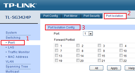
Port: Choose a port (assume it is port 1) you need to configure.
Forward Portlist: choose ports to which packets from port 1 can be forwarded.
Note: Since communications are bidirectional, if you want hosts under port 1 to communicate with hosts under port 2, you need both port1’s forward portlist allow port 2 and port2’s forward portlist allow port 1.
An example:

Topology:
PC1 connect to port 1, PC2 connect to port 2, PC3 connect to port 3, server A connect to port 4, server B connect to port 5.
Goal:
PC1, PC2, PC3 can’t communicate with each other, PC1 can access both server A and server B, PC2, PC3 can only access server A.
The configuration process is as follows:
Step1: Open the browser and log in the management-page of the switch.
Step2: After log in, please go to: Switching->Port->Port Isolation->Port Isolation Config.
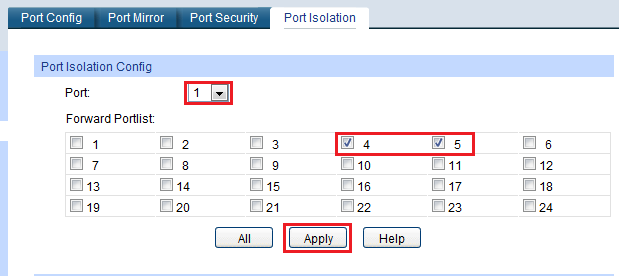
Step3: Configure each port as below:
For port1:
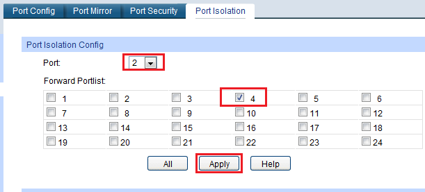
For port2:
For port3:
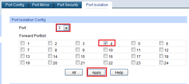
For port4:
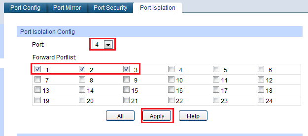
For port5:
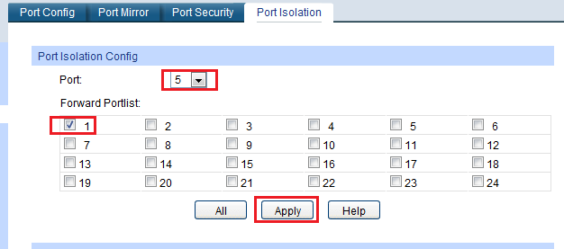
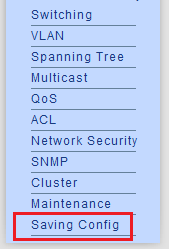
Click Saving Config to save the configuration file.
If configure like this, PC1 can access both server A and server B, PC2 and PC3 can only access server A. Three PCs can’t communicate with each other.
Get to know more details of each function and configuration please go to Download Center to download the manual of your product.
A fost util acest FAQ?
Părerea ta ne ajută să îmbunătățim acest site.