


How to configure RSTP on TP-Link switches using the old GUI
STP (Spanning Tree Protocol), subject to IEEE 802.1D standard, is aimed at disbranching a ring network in the Data Link layer of local area network. Devices running STP can discover loops in the network and block ports by exchanging information. Then a ring network can be disbranched to form a tree-topological no ring network to prevent broadcast storm. RSTP refers to deliver a very fast way to convergence.
Now let’s learn how to configure RSTP on TP-Link Switches by the following example:
Network Topology:
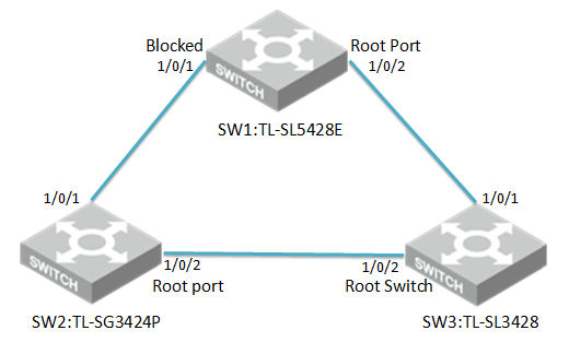
Three switches are under the same VLAN
Attention:
- Please configure the RSTP of switches first and then connect them together to avoid the broadcast storm.
- In this test we will let three switches elect root switch automatically. If you want to set a specific switch as root switch, please set CIST priority number of the switch smallest among three.
Here we take TL-SG3424P、TL-SL5428E and TL-SL3428 as an example.
The connection of three switches shows as the topology.
Configuration steps:
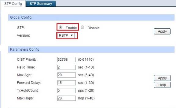
- Choose the menu Spanning Tree→STP Config→STP Config to load the following page, Enable STP and select version RSTP on Three switches.
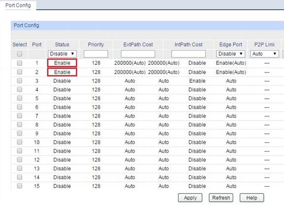
2. Choose the menu Spanning Tree →Port Config and Enable the
Up-link port status on TL-SG3424P、TL-SL3428 and TL-SL5428E.
The Up-link port is the port which connected to other switches.
3. Then we can see three switches elected the root switch TL-SL3428 via RSTP through menu Spanning Tree→STP Config→STP Summary.
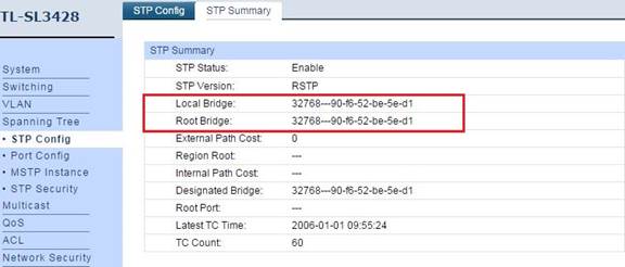
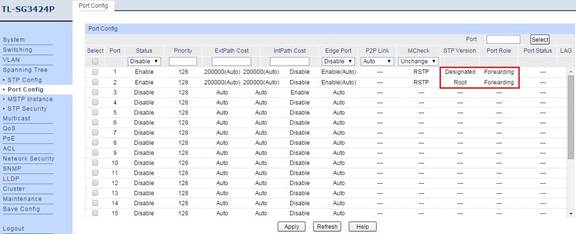
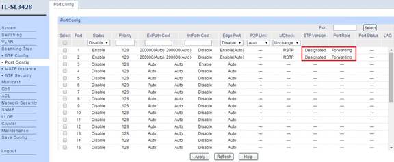
4. We can see the STP version and port role on three switches.
TL-SG3424P
TL-SL3428
TL-SL5428E
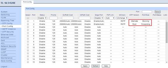
5. Now we can make clear which port was blocked via RSTP. From the port role we can see port 1 of TL-5428E was blocked.
So the finally topology is the following:
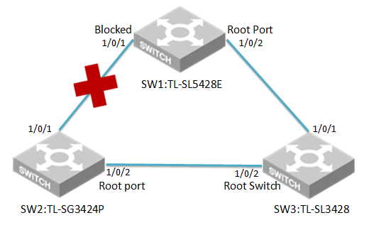
Finally, the network will work normally.
Czy ten poradnik FAQ był pomocny?
Twoja opinia pozwoli nam udoskonalić tę stronę.


z United States?
Uzyskaj produkty, wydarzenia i usługi przeznaczone dla Twojego regionu.