


How to configure Multiple SSIDs with Multiple Subnets on EAP products
Apply for: EAP Products
In enterprise network, we usually need to divide the network into different VLANs to isolate broadcast domain, suppressing the bad influence of broadcast traffic on network’s performance. The enterprise network is usually divided by different apartments, such as R&D, Marketing, and Product, etc. While nowadays since the wireless devices (like smartphone and laptop) are being used more and more frequently in office, the IT department has to configure each VLAN with the different wireless network (SSID) to meet these office needs. In this document, we will give you a simple step-by-step guide to this kind of configuration by use of TP-Link SMB router/switch and EAP/EAP Controller solution.
Included devices:
AP: EAP Products, such as EAP225
SMB Switch: L2+or L3 Switches, such as T2600-28TS
SMB Router: Multi-net NAT Available Routers, such as TL-ER6120
Topology:
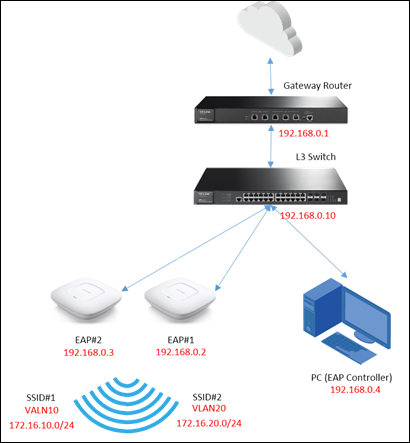
Step1. Configure Multi-Nets NAT and Static Route on the Gateway Router
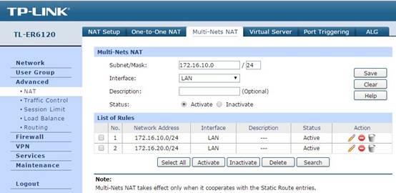
(1)Multi-Nets NAT Configuration:
Since there are multiple subnets requiring NAT service, the gateway which works as a NAT device needs to support Multi-Nets NAT. In gateway router’s Web UI, you can configure it in Advanced -> NAT -> Multi-Nets NAT as the figure shows below.
Configure the IP and subnet mask of each subnet, and each item works for one subnet. Leave Interface as LAN.
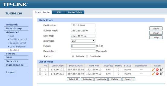
(2)Static Route configuration
In Advanced -> Routing -> Static Route, you can configure the static route items, the static route configuration helps the data packet from WAN find the next hop, the L3 switch. So in this part, the Destination is the subnet’s network address, and Next Hop is the switch’s IP, and Interface is still LAN.
Now the configuration on the gateway router is done, next we will configure the switch.
Step2. Configure VLAN and Port Attribute on Switch
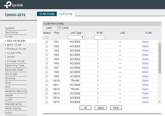
(1)Port Attribute Configuration:
In VLAN -> 802.1q VLAN -> Port Config, set the ports connected to EAP as Trunk mode (Port 1/0/10 and 1/0/12 in this topology). The port in Trunk mode can transmit data packets with different VLAN tags. Set PVID as 1.
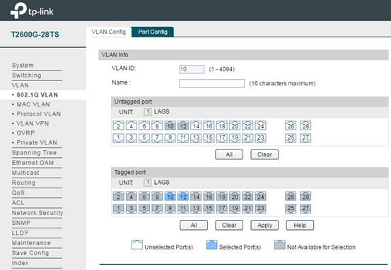
(2)VLAN Configuration
In VLAN -> 802.1q VLAN -> VLAN Config, add the ports connecting the switch and EAP to VLAN, here we take VLAN 10 and VLAN 20 as examples.VLAN10 and VLAN20 both have member ports 1/0/10 and 1/0/12.
Step3. Configure L3 Interface and DHCP Server for VLAN on Switch.
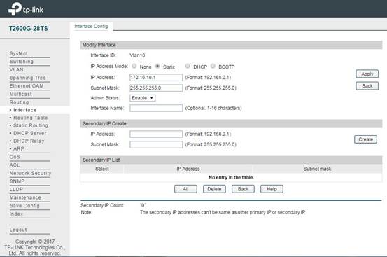
(1)VLAN’s L3 Interface Configuration:
In Routing -> Interface -> Interface Config, add L3 interface for the VLAN configured in previous steps. So VLAN can communicate like a normal subnet on IP Layer. IP Address Mode usually is selected as Static. IP Address and Subnet Mask specify the default gateway and network size for the subnet.
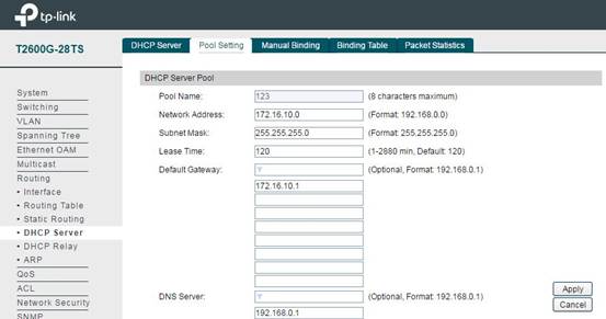
(2)DHCP Server Configuration for each subnet:
After configuring L3 interface for VLAN, we also need to set up DHCP Server for each subnet to assign IP for the wireless clients. In Routing -> DHCP Server -> Pool Setting, you can configure IP address pool for each subnet. Network Address and Subnet Mask specify the size of the address pool. Default Gateway specifies the default gateway for the subnet to which the address pool is bound. The DNS server specifies the corresponding DNS server. These configurations will be sent to the clients during DHCP process.
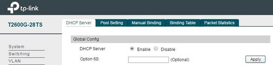
Note: The DHCP Server is disabled by default, so after configuring the DHCP address pool, please don’t forget to enable the DHCP Server. Or your wireless devices connected to the SSID can’t obtain an IP address.
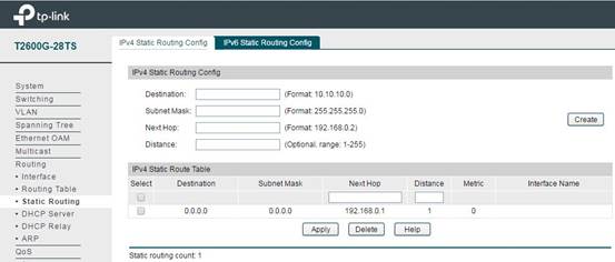
Step4. Static Route Item Configuration on Switch
In Routing -> Static Routing -> IPv4 Static Routing Config, you can add the static route items like the following figure shows. The purpose of this static route item is to forward all the data packets received by the switch to the front gateway router successfully. So the Destination IP 0.0.0.0 means any data packets with any destination IP will be forwarded to 192.168.0.1 (the gateway router).
Then the configuration on the gateway router is also done, and next we will configure the EAP Controller.
Step5. Configure SSID items with VLAN ID on EAP Controller
Run EAP Controller and after successfully Adopt EAP, add new SSID in Setting -> Wireless Settings. Add the previously configured VLAN ID in the Wireless VLAN ID section.
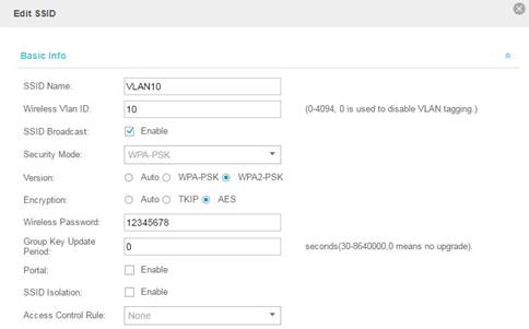
Configure two SSIDs, name them as VLAN10 and VLAN20. Use the terminal device to connect the two SSIDs and we can see the IP addresses assigned to the terminal device are 172.16.10.3 and 172.16.20.3. And the terminal can access the Internet which means the configuration has been successful.
Czy ten poradnik FAQ był pomocny?
Twoja opinia pozwoli nam udoskonalić tę stronę.
4.0-F_normal_20221110005015k.png)
4.0-F_normal_1593323303811i.png)
z United States?
Uzyskaj produkty, wydarzenia i usługi przeznaczone dla Twojego regionu.