How to configure IGMP Snooping for IPTV network using L2 switch
This FAQ is suitable for Easy Smart Switch, Smart Switch, L2 Managed Switch
IPTV service consists of three entities-multicast source, client device and multicast network. This Article will focus on the most frequently asked scenarios of IGMP snooping Multicast network in the Access Layer. And give you the corresponding suggested configuration guide.
Scenario:
IGMP snooping on L2 switch for Multicast network in the Access Layer.
Note: The gateway router must support IGMP proxy/query function or IGMP snooping on L2 switch will not work as expected.
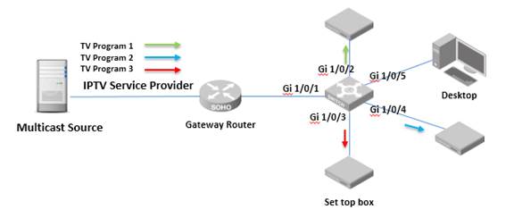
Topology:

Target/Requirement:
Using a TP-Link L2 switch’s IGMP snooping feature to build up a L2 multicast network to avoid broadcast of multicast data.
Configuration Guidance:
As illustrated in the topology above, Internet Gateway Router is connected to the L2 switch via port 1. “Set top box” is connected to L2 switch via port 2/3/4 for IPTV service, port 5 of the switch is connected with Desktop and there is no IPTV service on it.
Here we take Easy Smart switch TL-SG105E and Smart Switch T1600G-28TS as the instances to show how to enable IGMP snooping. For L2 managed switch and L3 managed switch configuration on IGMP snooping, it is the same with the configuration of T1600G-28TS.
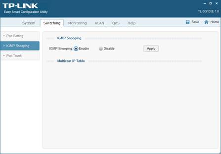
TL-SG105E Utility Configuration:
Step 1: log in the Configuration Page of TL-SG105E.
Step 2: Enable IGMP Snooping in “Switching-IGMP Snooping”
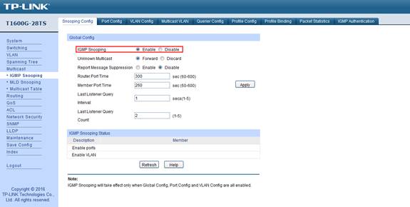
T1600G-28TS Web GUI Configuration:
Note: Set top box and Desktop and Router are in the same VLAN 1, it is the factory default settings.
Step 1: Log in the Configuration Page of T1600G-28TS.
Step 2: Enable IGMP Snooping in “Multicast-IGMP Snooping-Snooping Config”
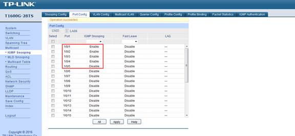
Step 3: Enable IGMP Snooping for port 1,2,3,4 in “Multicast-IGMP Snooping-Port Config”. Please note port 5 is not needed for IPTV services, so we do not enable port 5 for IGMP snooping. If the desktop computer is also to receive the multicast service, Just Enable port 5.
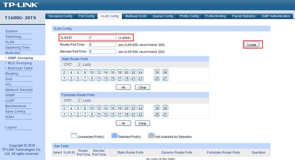
Step 4: Create “VLAN 1” for IGMP snooping VLAN Config. In this instance, all devices are in VLAN1, so we can create VLAN1 and enable the IGMP snooping for VLAN1. Or if your network has more than one VLAN in the multicast network, you should either create the VLAN ID needed for multicast service one by one.
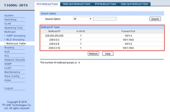
Step 5: Check the Multicast Table in “Multicast-Multicast Table”, from the table, we can clearly see that Port 2 and Port 3 and Port 4 are receiving different Programs (marked by different multicast IP address) via Port 1(Gateway Router Port) from the multicast source.
Note: Port 5 is not going to receive any multicast data, so port 5 is not in the multicast table list.

Get to know more details of each function and configuration please go to Download Center to download the manual of your product.
Czy ten poradnik FAQ był pomocny?
Twoja opinia pozwoli nam udoskonalić tę stronę.


z United States?
Uzyskaj produkty, wydarzenia i usługi przeznaczone dla Twojego regionu.