How to configure VLAN with Omada Network v6
Configuration with an Omada device as DHCP server
Configuration with external DHCP server or without DHCP server
Introduction
We are aware that significant changes regarding LAN settings have been made from Omada Network v5 to v6. This article introduces how to configure the VLAN feature with newest Omada Network v6 to help you establish a better understanding of the workflow of how to configure VLAN with Omada Controller v6.
Requirements
- Omada Controller
- Omada gateway/switch (optional)
Configuration
Configuration with an Omada device as DHCP server
Step 1. To create a new VLAN on the Controller. Go to Network Config > Network Settings > LAN and click Add under the column VLAN after logging into controller
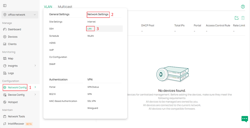
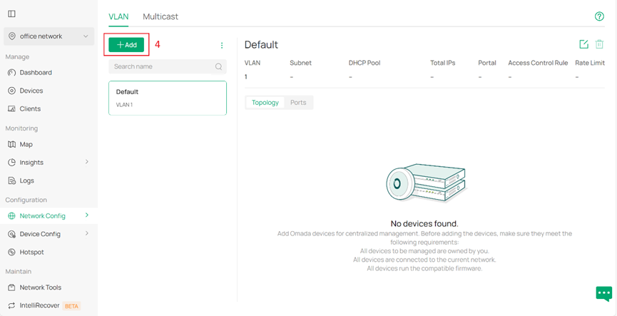
(These two pictures show buttons for creating new VLAN.)
Then we start with basic configuration.
Select the device where you wish to set up a DHCP server as DHCP Server Device. It can be a gateway or L3 switch that support DHCP services.
Specify the Name, VLAN ID as well as Subnet for the new network. If you mean to maintain a network with static IP addresses, you may disable DHCP feature.
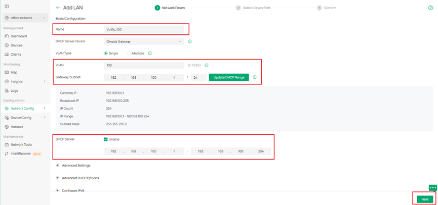
(Columns in which you need to fill to configure a new VLAN when Omada gateways works as DHCP server.)
If using Omada switch as DHCP server, these parameters need to be configured manually according to your needs. Select Static for IP Address Mode and specify the IP Address and Subnet Mask. Select DHCP Server for DHCP Mode and enter the required parameters such as DHCP Range and DNS Server.
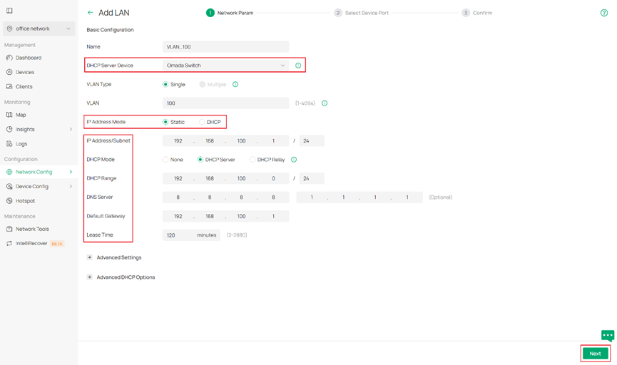
(Columns in which you need to fill to configure a new VLAN when Omada switch works as DHCP server.)
You may also configure advanced network settings including Snooping, Legal DHCP Servers and DHCP L2 Relay in Advanced Settings, and configure DHCP option 138 and custom DHCP options according to your own needs in Advanced DHCP Options. You may refer to other FAQ for the detailed information about these features if you have any further questions.
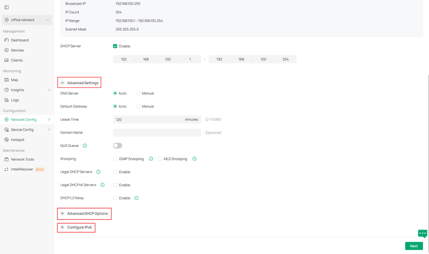
(Advanced settings including QoS, snooping, etc. to satisfy advanced needs.)
After finishing configuring all you need, click Next to continue.
Step 2. Select Device Port. In the following page, you will select device ports. To do this, you will click the device which you want to configure first and then select their ports where this set of VLAN configuration will be applied. Be aware that for switch ports, if a port remains unselected for any VLAN configuration, it turns out to be a trunk port possessing every VLAN to sustain connectivity. You may also enable our recommended features such as port isolation and flow control on these access ports. Then click Next to continue.
Note: We recommend you select ports which would be the access ports of your network (ports that connect to hosts or clients, e.g. PC) on your switches in this step. While for the gateway, if a branch needs it, you are supposed to enable it. A result is given in step 3 to explain how it behaves.
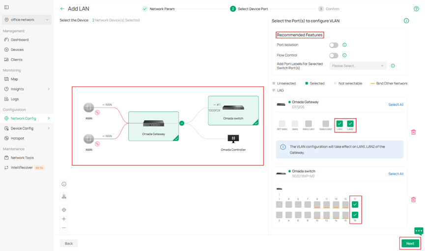
(Select ports where the newly configured VLAN is expected to be applied.)
Step 3. Confirm what you have just configured. If it shows as expected, click Apply to finish.
For what is demonstrated in our series of screenshots in this FAQ, we will get a gateway whose ports LAN1 & LAN2 are having VLAN 100 with DHCP server on it, and a switch with its ports 17&18 to be the access ports for VLAN 100 as well as its ports 1-8 to be the trunk ports possessing multiple VLANs including VLAN 100 and any other VLAN you previously configured. (ports 9-16 have been equipped with other VLAN and been configured as access ports of that VLAN previously).
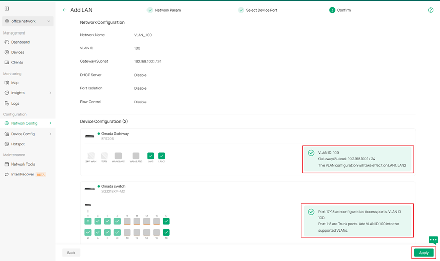
(A conclusive confirmation about what we just did before it comes into play.)
Note: To further configure the switch port's network settings, like PVID, tag/untag etc., please go to the switch details page and edit the port if more configuration actions are needed.
Configuration with external DHCP server or without DHCP server
Sometimes you may not be willing to set a DHCP server on Omada devices but want to add an existing VLAN, which may have been already well configured on routers or firewalls from other vendors to your downstream Omada devices, like EAPs or access switches. Or what you want is simply a pure layer 2 network with static IP addresses.
For these scenarios, what differs from the previous stage is that you need to select External Devices or None when selecting DHCP server Device.
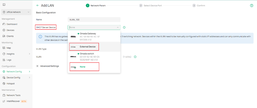
(Settings when you try to configure with external DHCP server or without DHCP server.)
The rest of the remaining part is basically the same workflow as the first stage.
Verification
In this chapter we demonstrate an example stage of network office configuration to illustrate how VLAN is set with Omada Network 6.0. Network design as picture shown below.
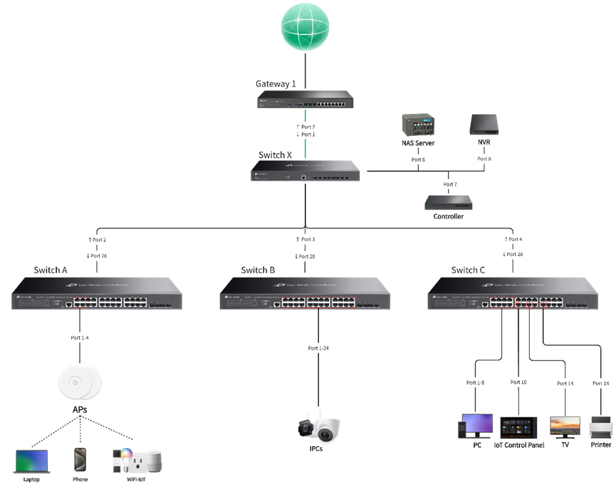
(An example of network design for small office.)
For VLAN regulation of this instance, we plan to use VLAN 1 for network device management, VLAN 10 for employee PCs, VLAN 20 for guest access, VLAN 30 for security devices inside the office and VLAN 40 for IoT equipment. Their IP range and port planning as detailed with the following charts.
|
Network Name |
Usage |
VLAN ID |
Gateway/IP Range |
Ports |
SSID |
|
Default |
Default management network for network infrastructure devices and system administration |
1 |
192.168.0.1/24 |
SW A port 1-4 |
/ |
|
PC Network |
Primary employee network for desktop computers and workstations |
10 |
192.168.10.1/24 |
SW C port 1-4 |
/ |
|
Guest Network |
Isolated network for guest users with limited internet access only |
20 |
192.168.20.1/24 |
/ |
Guest SSID |
|
Security Network |
Dedicated network for security cameras, access control systems and surveillance equipment |
30 |
192.168.30.1/24 |
SW B port 1-24 |
/ |
|
IoT Network |
Segregated network for smart devices, sensors, and IoT equipment with controlled access |
40 |
192.168.40.1/24 |
SW C port 10,14,18 |
IoT SSID |
Here we take configuration of VLAN 10 as example, the configuration method for other VLANs is similar to this one. After we connect all devices in order, we start with creation of VLAN 10 since VLAN 1 is generated by default. Click add on the top left to enter the edit page.
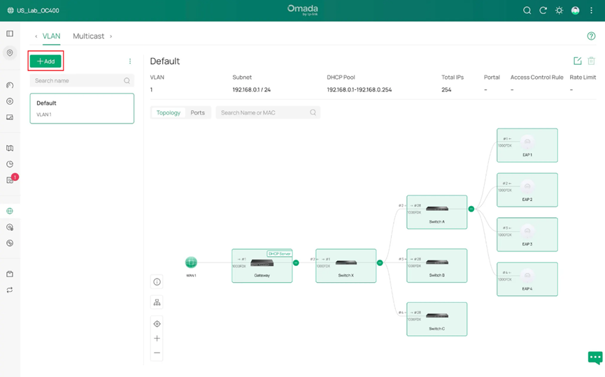
(Clicking Add to generate a new VLAN.)
We create VLAN 10, select Omada gateway as DHCP server with DHCP service enabled and name it PC Network.
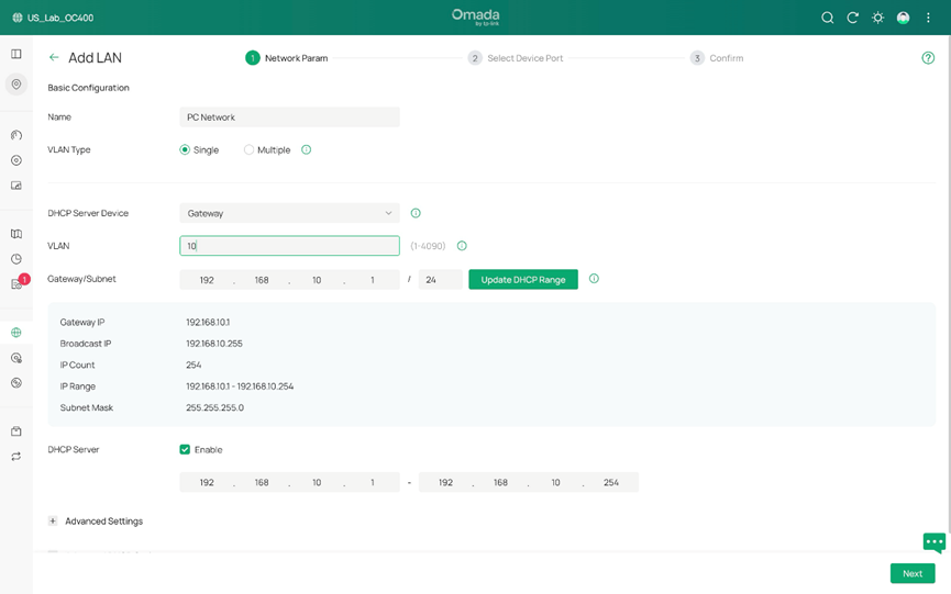
(We choose gateway as DHCP server, creating VLAN 10 as we need in this instance.)
Then we select the ports which are expected to be the access ports of PC Network, 4 PCs and 1 NAS included. We grant them access to VLAN 10. This can be achieved by either tickle the ports one by one or a drag from blank covering multiple ports. Red garbage can icon is used for clearing all ports that are selected. Don’t worry about uplink ports, they will be containing VLAN 10 after configuration is completed as long as they remain as trunk ports.
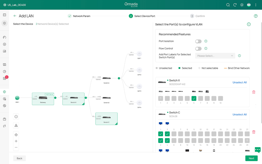
(We determine the ports to be the access ports of PC Network in this example.)
After that, we push forward to the confirmation page. It behaves as we expected, so we click Apply to finish. And it is completed for generating a VLAN.
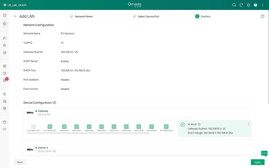
(Confirmation page, used for checking what the result would turn out to be like.)
Now, we are going to demonstrate how to edit existing VLAN configuration.
Given that we have 4 more new workers coming to add join, we need to add four more PCs into office network, which means, to VLAN 10.
To do this, after connecting the 4 new PCs to port 5-8 of switch C, we go to Network Config > LAN, find PC Network(VLAN 10) on the left side and click edit button on the right side. In the following page you may edit network parameters for this VLAN. Yet it is not needed in the example scenario, we will simply skip it to the next page where access ports will be defined.
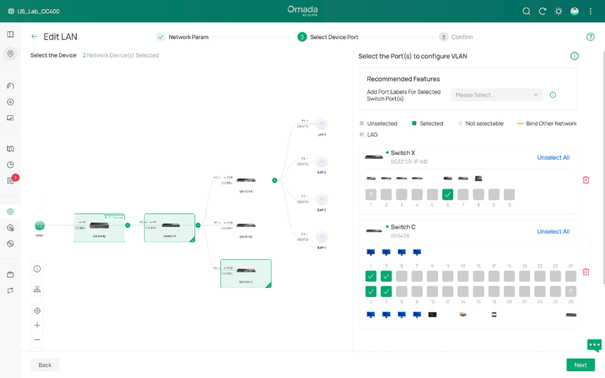
(Editing the device ports to be adapted to new actual scenario.)
As we click switch C to open its port details, you could see it is shown here that we have detected 4 new PCs with port 5-8. Now with similar move we select port 5-8 and make them access ports of VLAN 10 as well.
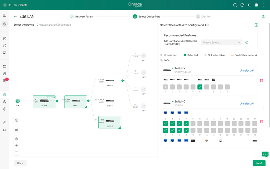
(Four more ports are added to be the access ports of VLAN 10.)
Lastly, it’s confirmation phase for checking the status of VLAN 10. If it behaves as what you want, click Apply and the edit is then completed.
Conclusion
These are steps of how to create VLAN with the newest Omada Network v6. Simply speaking, it follows a sequence of configurating parameters, selecting ports, confirmation and repeat for a different VLAN. Editing existing VLAN follows this order as well.
For veterans to quickly get what has been changed, as you may have already discovered, a major difference is that VLAN configurations now are independent and no longer related to switch profile.
Our old pattern works like “Network > Port Profile > Switch Port”, VLAN in switch port cannot be directly modified, you have to change the contents in Port Profile to realize the modifications to VLAN in switch port. And for now, it works like “Network > Switch Port”, we firstly configure VLAN for overall network, if further adjustments are needed, then we move directly to switch port/ports (drag your mouse to select multiple units) in device details page and directly modify tag, PVID, etc. specification for advanced configurations.
This article applies to: Omada network over version 6.0, Omada devices with their firmware supporting network 6.0 or above