


Come progettare e implementare la tua rete con Omada Design Hub?
Omada Design Hub (https://design.tplinkcloud.com/) is a free online network planning tool, offering a convenient and visualized platform to easily plan your network and select the most suitable network products to deploy. AI tools are also available to facilitate your planning process.
This step-by-step guide will take a two-story office for example to help you design and deploy your network using Omada Design Hub.
1. Access Omada Design Hub
To access Omada Design Hub, visit https://design.tplinkcloud.com/. You will need a TP-Link ID to sign in. If you do not have an account, create one first.
To create a TP-Link ID: Visit https://community.tp-link.com/en/register and enter all the required information. After clicking “Register,” you will receive an activation email. Click the link in the email to activate your TP-Link ID. Once activated, you will be able to login to Omada Design Hub.
2. Create a New Project
After logging in, follow these steps to create a new project:
Step 1) Click +Add in the Project List page.
Step 2) Specify a project name and select an appropriate scenario, such as “Office Network” as the project name and “Office” as the scenario. Click Confirm.
Note: If the predefined scenarios do not fit your need, click + Add New Scenario to customize your own scenario.
3. Create a New Floor
After creating your project, you will be automatically redirected to the following Floor Plan page. Follow these steps to create a new floor:
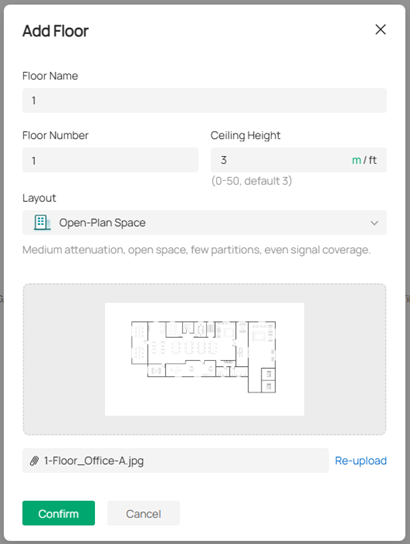
Step 1) Click Upload Floor Plan. Multiple formats are supported, but only one file can be uploaded at a time.
Step 2) Specify the floor name, floor number, and ceiling height. Select a layout most suitable for your map, which will make the simulation more accurate. Click Confirm.
Note:
- You can switch the unit for the ceiling height between meter and feet.
- You can click the image to preview it and re-upload another file if you want to change it.
3) After uploading the floor plan, you will need to set your floor plan scale. Left-click at a starting point to draw a line on the map and left-click again to finish drawing. Specify its length. Click Apply.
Note:
- Make sure the floor plan scale reflect the actual environment, as it impacts wall simulation, cable length, and wireless coverage.
- To reset the scale, click the scale icon in the bottom right.
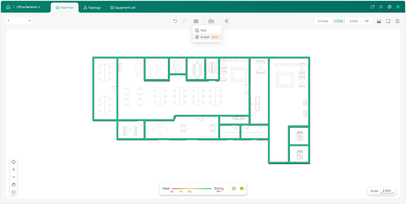
4. Draw Walls
Before deploying devices, draw walls for the floor to indicate obstructions.
Step 1) Click AI Wall to draft walls. The smart tool can help save you much time on the drawing process.
Step 2) Modify the walls manually. You can further add new walls, move, split, or delete the existing walls, and change the wall types.
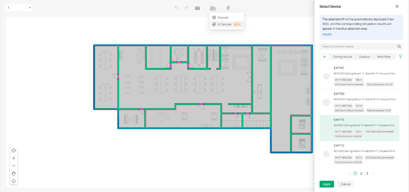
5. Deploy Devices
With your layout ready, start deploying devices. Similarly, use the AI tool first to streamline the process.
Step 1) Click AI Devices and select an AP model. Click Apply.
Note: Only Omada access points are currently available for AI Devices.
Step 2) Click a specific band to view the Wi-Fi coverage and adjust the AP deployment.
Note: Hover your mouse over an AP to visualize its Wi-Fi coverage on the heat map.
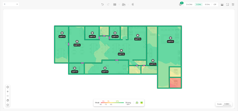
3) Add gateways, switches or extra APs manually based on your actual need. Click Devices and select a model. Place the device to a desired location.
6. Deploy Cables
-
In a single floor
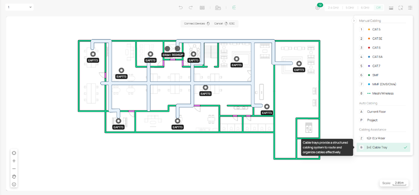
After properly placing the devices, deploy cables to connect these devices for the current floor.
Step 1) Click Cable and Cable Tray to design a structured cabling system to route and organize cables effectively based on your actual environment.
Step 2) Use Auto Cabling to facilitate fast deployment. Modify the cabling result according to your needs. Click Confirm.
Step 3) Adjust the cabling manually.
-
Across multiple floors
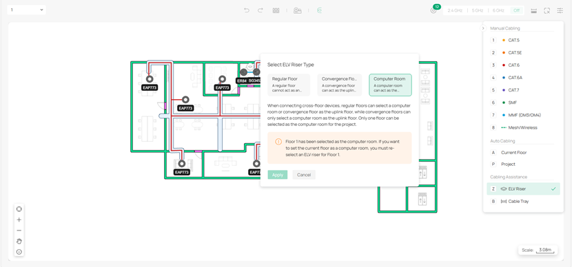
Auto Cabling also supports multi-floor cabling within a project.
Step 1) Follow the same procedure above to create the second floor.
Step 2) Deploy an ELV riser on each floor and select the ELV riser type for the floor.
Note: Cross-floor devices need to be connected through ELV risers.
Step 3) Use Auto Cabling for the project and adjust the cables.
7. View Topology
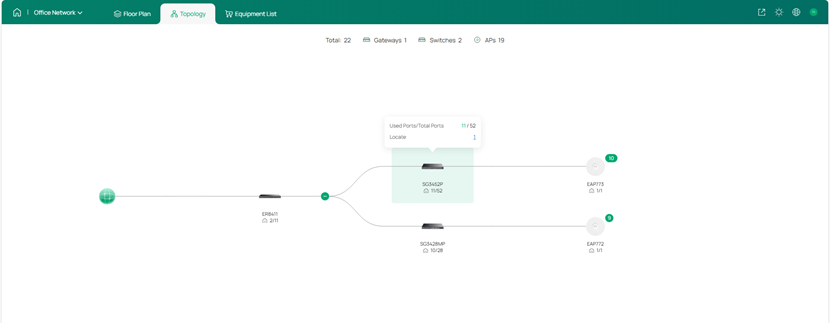
Click Topology on the top to view the network topology of the whole project. Hover over a specific device to check its port usage and locate the device.
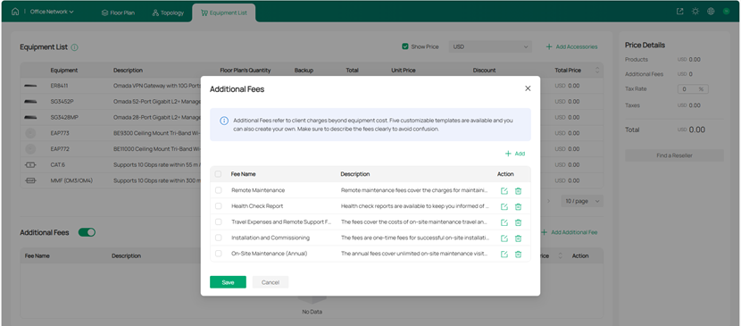
8. Check Equipment List and Fees
1) Go to Equipment List to check the devices deployed and the accessories. You can specify the quantity and unit price to calculate the total cost of your deployment.
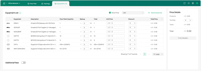
2) You can also add additional fees according to your needs.
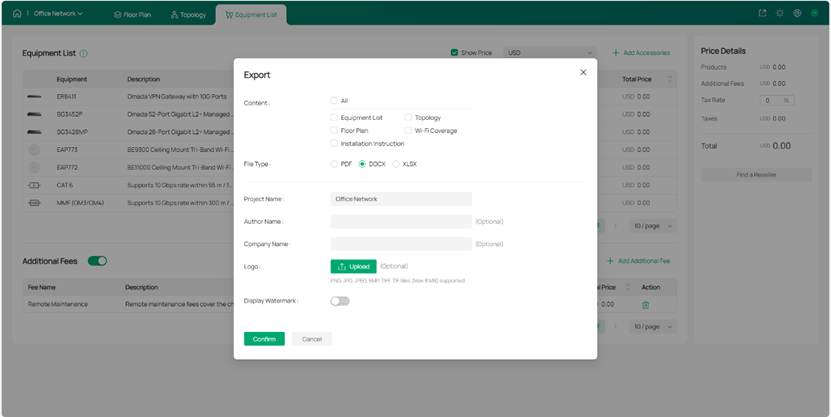
9. Export Network Design Report
Once you are satisfied with your network plan, you can export a report for actual network deployment reference.
For detailed guidance, refer to the user guide of Omada Design Hub.
For more details of Omada Design Hub, refer to the landing page of Omada Design Hub.