FAQ: Ethernet Switching
|
|
This guide applies to: T1500/T1500G/T1600G/T1700G/T1700X/T2500/T2500G/T2600G/T2700G/T3700G |

1 How Do I Create VLANs in a Batch?
In global configuration mode, enter vlan vlan-list command to create VLANs in a batch.
Create 10 contiguous VLANs in a batch: VLAN 10-19
Switch#configure
Switch(config)#vlan 10-19
Create 10 discrete VLANs in a batch: VLAN 2-9,20,30
Switch#configure
Switch(config)#vlan 2-9,20,30
2 How Do I Decide the Link Type of a Port When Configuring VLANs?
T2500/T2500G/T2600G/T2700G/T3700G/T3710G series switches support three link types: Access, Trunk, and General (equal to the type Hybrid in some non-TP-Link devices).
Configure the link type and egress rule of each port according to the following information when deploying your network.
Table 1Behavior of Link Types
|
Link Type |
Behavior |
|
Access |
The port can belong to only one VLAN. When receiving frames: •The port accepts untagged frames and adds a VLAN tag with the PVID to the frames. •The port accepts the tagged frames if the frames’ VLAN IDs match its PVID. •The port drops the tagged frames if the frames’ VLAN IDs differ from its PVID. When forwarding frames: The port forwards the frames without tag. |
|
Trunk |
The port can belong to multiple VLANs. When receiving frames: •The port adds a VLAN tag with the PVID to the untagged frames, and then decides to accept or drop the frame according to whether the PVID is in the port’s allowed VLAN list. •The port accepts the tagged frames if the frames’ VLAN ID are in its allowed VLAN list. •The port drops the tagged frames if the frames’ VLAN ID are not in its allowed VLAN list. When forwarding frames: Normally, the port forwards the frames with tags. If the frames’ VLAN tags match its PVID, the port will forward the frames without tag |
|
General |
The port can belong to multiple VLANs. When receiving frames: The behavior of a General port is the same with that of a Trunk port. When forwarding frames: The port decides to forward the frames with or without tag according to the egress rule. You need to specify the egress rule as tagged or untagged when adding the port to each VLAN. |
To simplify the VLAN configuration, T1500/T1500G/T1600G/T1700G/T1700X series switches only support General port.
|
|
Note: In future, all TP-Link switches will support the General link type only. |

3 How Do I Add Ports to a VLAN in a Batch?
You can add ports to a VLAN in a batch if these ports’ link types and egress rules are the same in your deployment plan.
T1500/T1500G/T1600G/T1700G/T1700X series switches only support General link type. You can add ports to a VLAN in a batch if the ports’ egress rules are the same in this VLAN.
The following example shows how to add ports Gi1/0/1-5 to VLAN 2 in a batch, and specify their egress rules as tagged:
Switch#configure
Switch(config)#interface range gigabitEthernet 1/0/1-5
Switch(config-if-range)#switchport general allowed vlan 2 tagged
Currently, T2500/T2500G/T2600G/T2700G/T3700G/T3710G series switches support three link types: Access, Trunk and General. You can add ports to a VLAN in a batch if these ports’ link types and egress rules are the same. In future, these switches will support General link type only.
The following example shows how to specify the link type of ports Gi1/0/1-5 as Access and add them to VLAN 2 in a batch:
Switch#configure
Switch(config)#interface range gigabitEthernet 1/0/1-5
Switch(config-if-range)#switchport mode access
Switch(config-if-range)#switchport access vlan 2
The following example shows how to specify the link types of ports Gi1/0/1-5 as Trunk, and add them to VLAN 2-3 in a batch:
Switch#configure
Switch(config)#interface range gigabitEthernet 1/0/1-5
Switch(config-if-range)#switchport mode trunk
Switch(config-if-range)#switchport trunk allowed vlan 2-3
The following example shows how to specify the link types of ports Gi1/0/1-5 as General, the egress rules as tagged, and add them to VLAN 2-3 in a batch:
Switch#configure
Switch(config)#interface range gigabitEthernet 1/0/1-5
Switch(config-if-range)#switchport mode general
Switch(config-if-range)#switchport general allowed vlan 2-3 tagged
4 How Do I Quickly View the Link Types and Default VLANs of All Ports?
In Privileged EXEC mode and any configuration mode, enter show interface switchport command to view the link types and Default VLANs (PVIDs) of all ports.
Switch#configure
Switch(config)#show interface switchport
Port LAG Type PVID
--------- ------ --------- --------
Gi1/0/1 N/A Access 1
Gi1/0/2 N/A Access 1
...
5 How Do I Delete a Single VLAN or VLANs in a Batch?
In global configuration mode, enter no vlan command to delete a single VLAN or delete VLANs in a batch.
Delete a single VLAN: VLAN 10
Switch#configure
Switch(config)#no vlan 10
Delete VLAN 2-9 in a batch
Switch#configure
Switch(config)#no vlan 2-9
6 How Do I Implement the Communication Among Different VLANs?
Only the switches with routing function support inter-VLAN communication.
After all VLANs are configured correctly, follow these steps to implement the inter-VLAN communication:
1)Create VLAN interfaces and assign IP addresses to the interfaces.
2)Configure the gateway of each PC as the IP address of the VLAN that the PC belongs to.
3)Enable the dynamic routing protocol like RIP, or create the static routes on the switches along the path to generate the routing entries.
Figure 1 Inter-VLAN Communication
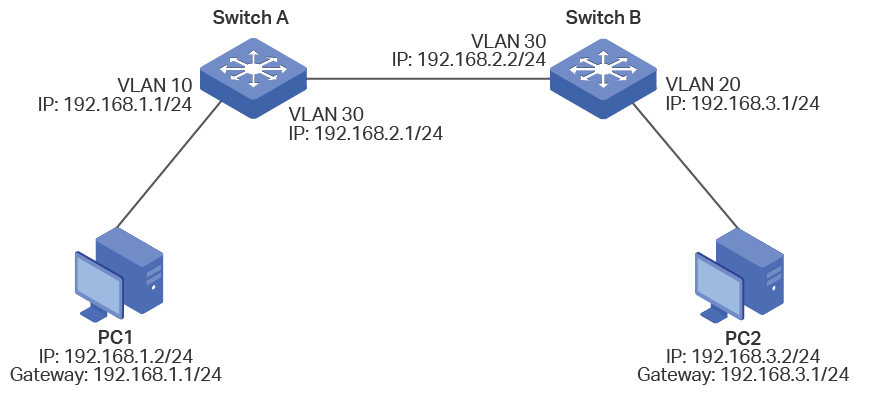
The configurations of Switch A and Switch B are similar. The following introductions take Switch A as an example.
1)Create VLAN interfaces VLAN 10 and VLAN 30, and assign IP addresses to the interfaces.
Switch_A#configure
Switch_A(config)#interface vlan 10
Switch_A(config-if)#ip address 192.168.1.1 255.255.255.0
Switch_A(config-if)#exit
Switch_A(config)#interface vlan 30
Switch_A(config-if)#ip address 192.168.2.1 255.255.255.0
Switch_A(config-if)#exit
2)Configure the gateway of PC1 as the IP address of VLAN 10 (192.168.1.1).
3)Create a static route with destination IP address 192.168.3.0/24 and next hop address 192.168.2.2.
Switch_A(config)#ip route 192.168.3.0 255.255.255.0 192.168.2.2
Switch_A(config)#show ip route
Codes: C - connected, S - static
* - candidate default
C 192.168.0.0/24 is directly connected, Vlan1
C 192.168.1.0/24 is directly connected, Vlan10
C 192.168.2.0/24 is directly connected, Vlan30
S 192.168.3.0/24 [1/0] via 192.168.2.2, Vlan30
7 How Many VLANs Does the Switch Support?
T1500/T1500G series switches support 512 802.1Q VLANs.
T1600G/T1700G/T1700X/T2500/T2500G/T2600G/T2700G/T3700G/T3710G series switches support 4094 802.1Q VLANs.
8 Does the Switch Support VLAN-VPN (QinQ)?
T2500/T2600G/T2700G/T3700G/T3710G series switches support both basic VLAN-VPN and VLAN mapping (flexible VLAN-VPN).
T1500/T1500G/T1600G/T1700G/T1700X series switches do not support basic VLAN-VPN or flexible VLAN-VPN.
9 What is the Difference Between Basic VLAN-VPN and Flexible VLAN-VPN (VLAN Mapping)?
Packets from the customer network may be tagged with different VLANs.
For basic VLAN-VPN, the switch will encapsulate the packets with the same outer VLAN tag of the service provider network.
For flexible VLAN-VPN, the switch maintains a VLAN mapping list. You can configure different VLANs in the customer network to map to different VLANs in the service provider network. If the received packets are tagged with customer VLANs in the list, the switch will encapsulate them with the corresponding service provider VLAN tags; otherwise, the switch will process the packet in the same way as basic VLAN-VPN does.
You need to enable basic VLAN-VPN before configuring flexible VLAN-VPN. Otherwise, the flexible VLAN-VPN configurations cannot take effect.
10 How Does a Port with VLAN-VPN (QinQ) Enabled Process a Packet?
With only basic VLAN-VPN enabled, all packets entering the service provider network through a VPN port of the switch are treated as untagged packets, no matter whether they are untagged or already tagged with IEEE 802.1Q headers.
The switch will check the MAC VLAN matching rules, protocol VLAN matching rules and the port’s PVID in sequence to decide the outer VLAN tag, and forward the packets within the outer VLAN.
If a match is found, the switch will encapsulate the packets with an outer tag that contains the corresponding MAC VLAN ID or protocol VLAN ID, and stop checking;
Otherwise, the switch will encapsulate the packets with an outer tag that contains the PVID of the VPN port.
With VLAN mapping enabled, when a VPN port receives a C-VLAN-tagged (Customer-VLAN-tagged) packet, the switch will encapsulate the packet with an outer tag that contains the corresponding SP-VLAN ID (Service Provider VLAN ID) according to the VLAN Mapping List. When a VPN port receives a non-C-VLAN-tagged packet or an untagged packet, the switch will process the packet in the same way as basic VLAN-VPN does.
11 What are the Causes of VLAN-VPN (QinQ) Traffic Forwarding Failures?
There are two causes of VLAN-VPN traffic forwarding failures:
The VLAN-VPN is configured incorrectly.
Switches along the path drop VLAN-VPN frames frequently.
To make sure the VLAN-VPN is configured correctly, follow the steps below:
1)Make sure the corresponding 802.1Q VLANs are configured correctly on the switches along the path. Figure 2 shows the typical topology of VLAN-VPN, and Table 2 shows the VLAN configurations on each switch.
Figure 2 Typical Topology of VLAN-VPN
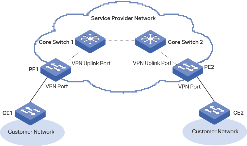
Table 2VLAN Configurations on Each Switch
|
Switch Roles |
VLANs to Be Created |
Member Ports and Egress Rules |
|
Customer Edge Switch (CE) |
Only Customer VLANs |
Configure the VLANs according to the customer network scheme. Normally, the egress rule of the uplink port (the port that is connected to the service provider network) should be configured as tagged. |
|
Service Provider Edge Switch (PE) |
Customer VLANs |
Add the VPN port (the port that is connected to the customer network) to this VLAN as a tagged port. |
|
Service Provider VLANs |
Add the VPN port to this VLAN as an untagged port, and configure its PVID as the service provider VLAN ID. Add the VPN uplink port (the port that is connected to the service provider core switch) to this VLAN as a tagged port. |
|
|
Service Provider Core Switch |
Only Service Provider VLANs |
Configure the VLANs according to the service provider network scheme, without considering the customer’s network. |
2)Check whether the ports are member ports of an LAG.
For T2500-28TC and T2500G-10TS, if the VLAN-VPN configurations of any port in an LAG are changed, the configurations of the other member ports in this LAG will also be changed. Please double check the VLAN-VPN configurations to ensure they are not changed for this reason.
For other TP-Link switches, when you create an LAG, an LAG logical interface is involved. The member ports of an LAG follow the VLAN-VPN configurations of the LAG logical interface but not their own. The configurations of the ports can take effect only after the ports leave the LAG.
The possible reason why the switches drop VLAN-VPN frames frequently is that lots of the VLAN-VPN frames are larger than the switches’ system MTU (Maximum Transmission Unit).
The VLAN-VPN feature increases the frame size by 4 bytes when the outer VLAN tag is added. It is possible to have multiple levels of tagging if the frames are transmitted by multiple VLAN-VPN enabled switches. You need to figure out the possible maximum frame size and configure all switches along the path to be able to process the maximum frames.
For TP-Link switches, the default system MTU are 1518 bytes. You can configure the switches to support frames larger than 1518 bytes by using the jumbo command in interface configuration mode.
|
|
Note: For T2600G-18TS, the default system MTU is 1518 bytes, you can specify the MTU by using the jumbo-size size command in interface configuration mode. |

12 Which Tag Does the TPID Configured by the dot1q-tunnel tpid Command Match?
The TPID configured by the dot1q-tunnel tpid command matches only the outer tag.
13 Which VLAN Does the Port Enabled with VLAN-VPN (QinQ) Obtain Through MAC Address Learning?
The VLAN-VPN (including basic VLAN-VPN and VLAN Mapping) implementation is prior to the MAC address learning. Therefore, after the VLAN-VPN implementation, the port obtains the outer VLAN through MAC address learning.
14 Why Do Some Configurations Fail After the Port Joins a Link Aggregation Group (LAG)?
For functions like IGMP Snooping, 802.1Q VLAN, MAC VLAN, Protocol VLAN, VLAN-VPN, GVRP, Voice VLAN, STP, QoS, DHCP Snooping, and the basic port parameters including Speed mode, Duplex mode, Jumbo size and Flow Control mode, the member ports of an LAG follows the configurations of the LAG logical interface but not their own. The configurations of the ports can take effect only after the ports leave the LAG.
|
|
Note: Exceptions include T2500-28TC and T2500G-10TS. For these switches, the LAG member ports follow their own configurations, and if the configurations of any port in the LAG are changed, the configurations of the other member ports will also be changed. |
15 How to Configure Load Balancing in a Link Aggregation Group (LAG)?
In global configuration mode, enter port-channel load-balance { src-mac | dst-mac | src-dst-mac | src-ip | dst-ip | src-dst-ip } command to configure the load-balancing algorithm for LAG. Table 3 shows the detail description of each option.
Table 3Load-balancing Algorithm
|
Load-balancing Algorithm |
Description |
|
SRC-MAC |
The computation is based on the source MAC addresses of the packets. |
|
DST-MAC |
The computation is based on the destination MAC addresses of the packets. |
|
SRC-DST-MAC |
The computation is based on the source and destination MAC addresses of the packets. This is the default option. |
|
SRC-IP |
The computation is based on the source IP addresses of the packets. |
|
DST-IP |
The computation is based on the destination IP addresses of the packets. |
|
SRC-DST-IP |
The computation is based on the source and destination IP addresses of the packets. |
Please properly choose the load-balancing algorithm to avoid data stream transferring only on one physical link.
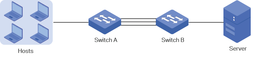
For example, as shown in Figure 3, Switch A receives packets from several hosts and forwards them to the server with the fixed MAC address and IP address, then both “DST-MAC” and “DST-IP” options are not recommended, because all the received packets have the same destination MAC addresses and IP addresses, and will be transferred on the same physical link. You can choose the other options as the load-balancing algorithm.
Figure 3 Hash Algorithm Configuration
16 Why Does the Bandwidth Not Increase After Link Aggregation Group (LAG) is Configured?
Please try the following:
1)Use the show etherchannel num summary command in privileged EXEC mode or any configuration mode to check whether the LAG link is up.
2)Make sure the load-balancing algorithm is configured properly.
The switch will choose the port to send the received packets according to the load-balancing algorithm. Please select the suitable load-balancing algorithm to make sure different data flows are forwarded on different physical links. For how to select the load-balancing algorithm, refer to
17 How Many Member Ports Does a Link Aggregation Group (LAG) of the Switch Support?
One static LAG supports up to eight member ports. All the member ports share the traffic evenly. If an active link fails, the other active links will share the traffic evenly.
One LACP LAG supports more than eight member ports, but at most eight of them can be active. Using LACP protocol, the switches negotiate parameters and determine the active ports. When an active link fails, the link with the highest priority among the inactive links will replace the faulty link and start to forward data.
18 Are TP-Link Switches’ STP Function Compatible with a Non-TP-Link Device’s?
TP-Link switches use the standard STP protocol. Whether a TP-Link switch’s STP function is compatible with a non-TP-Link device’s depends on the protocol running on the non-TP-Link device.
If the non-TP-Link device runs a standard STP protocol, including STP, MSTP, and RSTP, the TP-Link switch can work with it; Otherwise, the TP-Link switch cannot negotiate with the device.
19 Why Can’t the Switch Learn a MAC Address?
In privileged EXEC mode or any configuration mode, try the following:
1)Use the show mac address-table security vid vid command to check whether a MAC address learning limitation is configured in the VLAN that the port belongs to, and whether the number of MAC address entries learned by the VLAN has reached the limit.
2)Use the show mac address-table filtering command to check whether the MAC address is configured as the filtering address in the VLAN.
3)Use the show mac address-table static command to check whether a static MAC address is configured on the port and the VLAN.
20 How Do I Detect Loops on the Network?
You can use loopback detection function to detect loops on the network. Follow the steps below:
1)Use the loopback-detection command in global configuration mode to enable loopback detection globally.
2)Enter the interface configuration mode of the suspicious ports, and then run the loopback-detection command to enable loopback detection on these ports. If a loop is detected on these ports, the switch will send a trap and generate an entry on the log file.
21 In Which Scenario Can I Use Loopback Detection Function?
Loopback detection detects loops on a network by periodically sending loopback detection packets. There are two types of loops:
Loops that occur on a single port
If the detection packets are received by the same port, a loop occurs on this port. Two typical scenarios are shown below:
Figure 4 shows a self-loop on a port. The loop occurs when optical fibers are connected incorrectly or the port is damaged by high voltage.
Figure 4 A self-loop on a Port
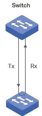
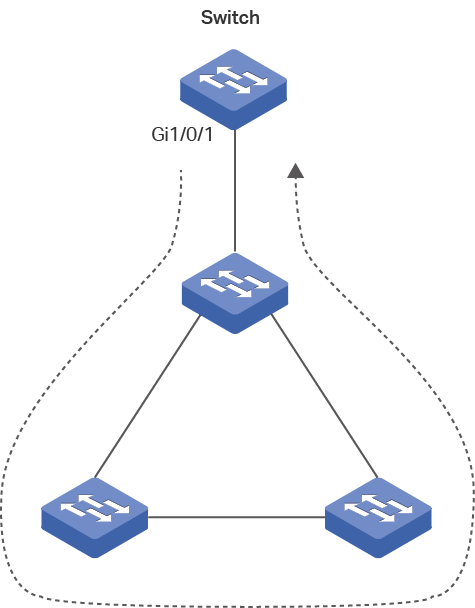
Figure 5 shows a loop on the downstream network of a port.
Figure 5 A Loop on the Downstream Network
Loops that occur between two ports
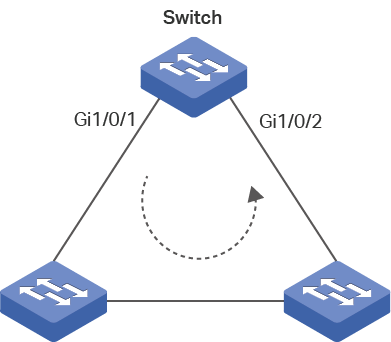
If the detection packets are received by another port of the switch, a loop occurs between the two ports. Figure 6 shows the typical scenario.
Figure 6 A Loop on the Network
22 Can the Switch be Configured Not to Block the Port After Detecting Loops?
You can configure the switch to send alerts and block the port, or only send alerts.
The alerts include sending a trap message and generating an entry on the log file.
To block the port, you can choose the block mode as port-based or VLAN-based.
Port-based: Totally block the port. No VLAN traffic can be forwarded on the port.
VLAN-based: Only block the traffic of the VLAN on which the loop is detected.
Suppose a port belongs to VLAN 1-3, and a loop is detected on VLAN 3. In port-based mode, the switch will block the traffic of VLAN 1-3 on this port, in VLAN-based mode, the switch will only block the traffic of VLAN 3, and still forward the traffic of VLAN 1 and VLAN 2.