Lightning Protection Guide
|
|
This guide applies to: TP-Link rack-mountable devices |

This guide applies to TP-Link rack-mountable devices. To identify if your device is rack-
mountable or not, check the IG (Installation Guide) of the device. The IG of rack-mountable device contains the content of “Rack Installation“.
You can find the IG from the package of the device or download it from the download center of our website http://www.tp-link.com/en/download-center.html.
In the actual network environment, you may need cable outdoors and indoors, and the requirements for cabling outdoors and indoors are different. A reasonable cabling system can decrease the damage of induced lightning to devices.
|
|
Note: It's not recommended using Ethernet cables outdoors. When cabling outdoors, please use a signal lightning arrester. |

Requirements for Cabling Outdoors
Aerial cabling without safeguard is not allowed.
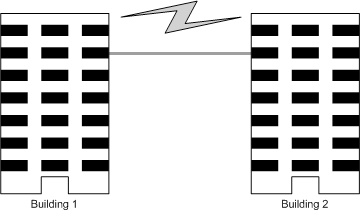
It’s not allowed cabling down the building to connect network devices in different floors.
Outdoor cables should be buried and paved to the indoor through basement. A piece of steel wire should be paved underground along the pipe and connected to the lightning protection terminal of the building for shielding. Before connecting the cable to the device, install a signal lightning arrester on the corresponding port.
When an aerial cable is set up, the cable should be through a metal pipe (15m long at least) before coming into the building. The two ends of this metal pipe should be grounded. Before connecting the cable to the device, install a signal lightning arrester on the corresponding port.
It’s not necessary to pave STP cables through pipes. The shielded layer of STP cable should be well grounded. Before connecting the cable to the device, install a signal lightning arrester on the corresponding port.
Requirements for Cabling Indoors
When cabling indoors, keep a certain distance away from the devices that may cause high-frequency interferences, such as down-conductor cable, powerline, power transformer and electromotor.
The main cable should be paved in the metal raceway of the access shaft. When cabling, keep the loop area formed by the cable itself as small as possible.
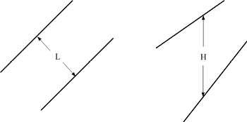
Requirements for the distance between Ethernet cable and other pipelines are shown in the table.
|
Other Pipelines |
Ethernet Cable |
|
|
Min Parallel Net Length L (mm) |
Min Parallel-overlapping Net Height H (mm) |
|
|
Down-conductor |
1000 |
300 |
|
PE |
50 |
20 |
|
Service pipe |
150 |
20 |
|
Compressed air pipe |
150 |
20 |
|
Thermal pipe (not wrapped) |
500 |
500 |
|
Thermal pipe (wrapped) |
300 |
300 |
|
Gas pipe |
300 |
20 |
The two diagrams below demonstrate parallel net length and parallel-overlapping net height.
|
|
Note: The above minimum net length/height is required when metal raceway is not used. If any requirements cannot be met, you can add a steel tube or metal raceway for shielding. |

Requirements for the distance between Ethernet cable and high-power electric devices are in following tables.
|
Cable |
Pave Way |
Min Parallel Length (mm) |
|
<2kVA powerline |
Parallel cabling |
130 |
|
One is in the grounded metal raceway or metal pipe |
70 |
|
|
The both are in the grounded metal raceway or metal pipe |
10 |
|
|
2 to 5kVA powerline |
Parallel cabling |
300 |
|
One is in the grounded metal raceway or metal pipe |
150 |
|
|
The both are in the grounded metal raceway or metal pipe |
80 |
|
|
>5kVA powerline |
Parallel cabling |
600 |
|
One is in the grounded metal raceway or metal pipe |
300 |
|
|
The both are in the grounded metal raceway or metal pipe |
150 |
|
Device |
Min Distance (m) |
|
Switch case |
1.00 |
|
Transformer room |
2.00 |
|
Elevator tower |
2.00 |
|
Air-conditioner room |
2.00 |
Connecting the device to ground is to quickly release the lightning over-voltage and over-current of the device, which is also a necessary measure to protect the body from electric shock.
In different environments, the device may be grounded differently. The following will instruct you to connect the device to the ground in two ways, connecting to the ground via the power supply or connecting to the ground via the grounding terminal. Please connect the device to ground in the optimum way according to your specific operation environment.
|
|
Note: For the device without grounding terminal, please refer to the first way Connecting to the Ground via the Power Supply only. |

Connecting to the Ground via the Power Supply
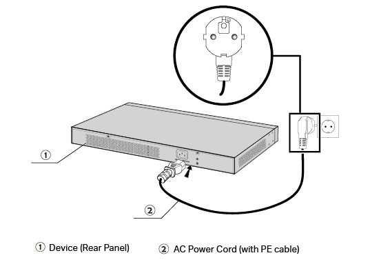
If the device is installed in the normal environment, the device can be grounded via the PE (Protecting Earth) cable of the AC power supply as shown in the following figure.
Figure 1 Connecting to the Ground via Power Supply
|
|
Note: •The figure is to illustrate the application and principle. The power plug you get from the package and the socket in your situation will comply with the regulation in your country, so they may differ from the figure above. •If you intend to connect the device to the ground via the PE (Protecting Earth) cable of AC power cord, please make sure the PE (Protecting Earth) cable in the electrical outlet is well grounded in advance. |

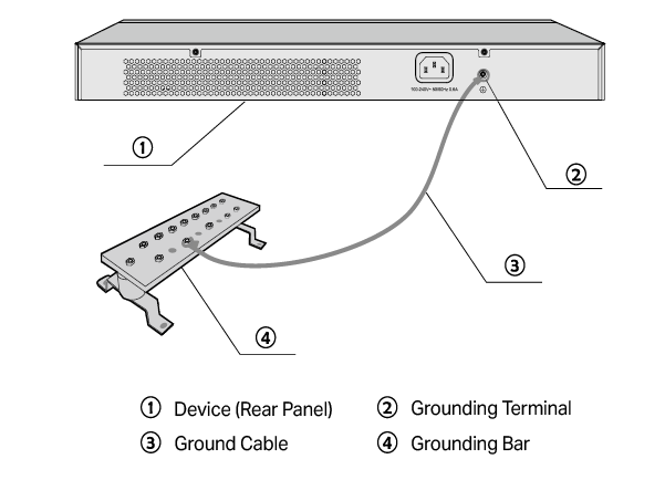
Connecting to the Ground via the Grounding Terminal
Use the grounding bar
If the device is installed in the Equipment Room, where a grounding bar is available, you are recommended to connect the device to the grounding bar as shown in the following figure.
Figure 2 Connecting to the Grounding Bar
|
|
Note: The grounding bar and the ground cable are not provided with our product. If needed, please self purchase them. |

Equipotential Bonding
Equipotential Bonding is the practice of intentionally electrically connecting all earthed systems to the same grounding grid or connecting the grounding grids of all the earthed systems together through the ground or overground metal so as to create an earthed equipotential zone. When lightning occurs, the high voltage produced by lightning current in all systems will meanwhile exist in their ground cables, and thus all ground cables have the same electrical potential and basically eliminate the electric strikes between the systems.
The figure below illustrates how to practice equipotential bonding in a network.
Figure 3 Equipotential Bonding
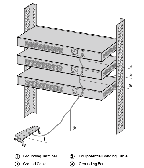
When equipotential bonding, please use a 10 AWG or larger ground cable. The shorter cable the better, and use a grounding bar to establish an equipotential bonding point.
|
|
Note: The equipotential bonding cable and ground cable are not provided with our product. If needed, please self purchase it. |

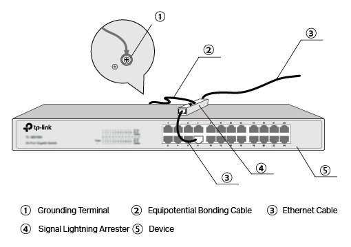
Use Lightning Arrester
Power lightning arrester and signal lightning arrester are used for lighting protection.
Power lightning arrester is used for limiting the voltage surge due to a lightning. If an outdoor AC power cord should be directly connected to the device, please use a power lightning arrester.
|
|
Note: Power lightning arrester is not provided with our product. If needed, please self purchase it. |

Signal lightning arrester is used to protect RJ45 ports of the device from lightning. When cabling outdoors, please install a signal lightning arrester before connecting the cable to the device.
When purchasing or using a signal lightning arrester, please observe the following rules:
»The port rate of the signal lightning arrester should match the rate of the desired port on the device. If it is not matched, this signal lighting arrester will not work. Purchase a standard lightning arrester.
»Install signal lightning arrester near the protected device and connect it to the ground via a shorter ground cable.
Figure 4 Use Lightning Arrester
|
|
Note: Signal lightning arrester is not provided with our product. If needed, please self purchase it. |
