Configuring Transmission
CHAPTERS
3. Bandwidth Control Configuration
4. Session Limit Configurations
5. Load Balancing Configurations
|
|
This guide applies to: TL-R470T+ v6 or above, TL-R480T+ v9 or above, TL-R600VPN v4 or above, TL-ER5120 v3 or above, TL-ER6020 v2 or above, TL-ER6120 v3 or above |

1.1Overview
Transmission function provides multiple traffic control measures for the network. You can configure the transmission function according to your actual needs.
1.2Supported Features
The transmission module includes NAT, Bandwidth Control, Session Limit, Load Balancing and Routing.
NAT
NAT (Network Address Translation) is the translation between private IP and public IP. NAT provides a way to allow multiple private hosts to access the public network using one public IP at the same time, which alleviates the shortage of IP addresses. Furthermore, NAT strengthens the LAN (Local Area Network) security since the address of LAN host never appears on the internet. The router supports following NAT features:
Multi-Nets NAT
Multi-Nets NAT function can help the router provide NAT translation for multiple subnets.
One-to-One NAT
One-to-One NAT creates a relationship between a private IP address and a public IP address. A device with a private IP address can be accessed through the corresponding valid public IP address.
Virtual Servers
When you build up a server in the local network and want to share it on the internet, Virtual Servers can realize the service and provide it to the internet users. At the same time Virtual Servers can keep the local network safe as other services are still invisible from the internet.
Port Triggering
Port Triggering is a feature used to dynamically forward traffic on a certain port to a specific server on the local network. When a host in the local network initiates a connection to the triggering port, all the external ports will be opened for subsequent connections. The router can record the IP address of the host, when the data from the internet returns to the external ports, the router can forward them to the corresponding host. Port Triggering is mainly applied to online games, VoIPs, video players and so on.
NAT-DMZ
When a PC is set to be a DMZ (Demilitarized Zone) host in the local network, it is totally exposed to the internet, which can realize the unlimited bidirectional communication between internal hosts and external hosts. The DMZ host becomes a virtual server with all ports opened. When you are not clear about which ports to open in some special applications, such as IP camera and database software, you can set the PC to be a DMZ host.
ALG
Some special protocols such as FTP, H.323, SIP, IPSec and PPTP will work properly only when ALG (Application Layer Gateway) service is enabled.
Bandwidth Control
You can control the bandwidth by configuring bandwidth control rules for limiting various data flows. In this way, the network bandwidth can be reasonably distributed and utilized.
Session Limit
The amount of TCP and UDP sessions supported by the router is finite. If some local hosts transmit too many TCP and UDP sessions to the public network, the communication quality of the other local hosts will be affected, thus it is necessary to limit the sessions of those hosts.
Load Balancing
You can configure the traffic sharing mode of the WAN ports to optimize the resource utilization.
Routing
You can configure policy routing rules and static routing.
Policy routing provides a more accurate way to control the routing based on the policy defined by the network administrator.
Static routing is a form of routing that is configured manually by adding non-aging entries into a routing table. The manually-configured routing information guides the router in forwarding data packets to the specific destination.
With NAT configurations, you can:
Configure the Multi-Nets NAT.
Configure the One-to-One NAT.
Configure the Virtual Servers.
Configure the Port Triggering.
Configure the NAT-DMZ.
Configure the ALG.
2.1Configuring the Multi-Nets NAT
Choose the menu Transmission > NAT > Multi-Nets NAT and click Add to load the following page.
Figure 2-1 Configuring the Multi-Nets NAT
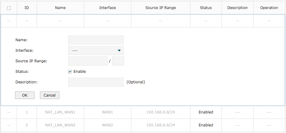
Follow these steps to configure the Multi-Nets NAT:
1)Specify the name of the Multi-Nets NAT rule and configure other related parameters.
|
Interface |
Specify the effective interface for the rule. |
|
Source IP Range |
Specify the source IP range for the rule. |
|
Status |
Check the box to enable the rule. |
|
Description |
Give a description for the rule entry to facilitate your management. |
2)Click OK.
2.2Configuring the One-to-One NAT
Choose the menu Transmission > NAT > One-to-One NAT and click Add to load the following page.
Figure 2-2 Configuring the One-to-One NAT
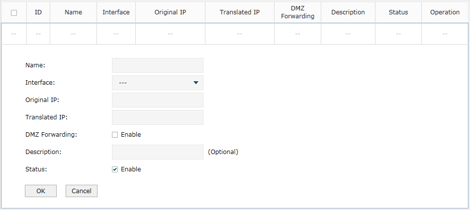
Follow these steps to configure the One-to-One NAT:
1)Specify the name of the One-to-One NAT rule and configure other related parameters.
|
Interface |
Specify the effective interface for the rule. |
|
Original IP |
Specify the original IP address for the rule. The original IP address cannot be the broadcast address, network address or IP address of the interface. |
|
Translated IP |
Specify the translated IP address for the rule. The translated IP address cannot be the broadcast address, network address or IP address of the interface. |
|
DMZ Forwarding |
Check the box to enable DMZ Forwarding. The packets transmitted to the translated IP address will be forwarded to the host of original IP address if DMZ Forwarding is enabled. |
|
Description |
Give a description for the rule entry to facilitate your management. |
|
Status |
Check the box to enable the rule. |
2)Click OK.
|
|
Note: One-to-One NAT take effects only when the connection type of WAN is Static IP. |

2.3Configuring the Virtual Servers
Choose the menu Transmission > NAT > Virtual Servers and click Add to load the following page.
Figure 2-3 Configuring the Virtual Servers
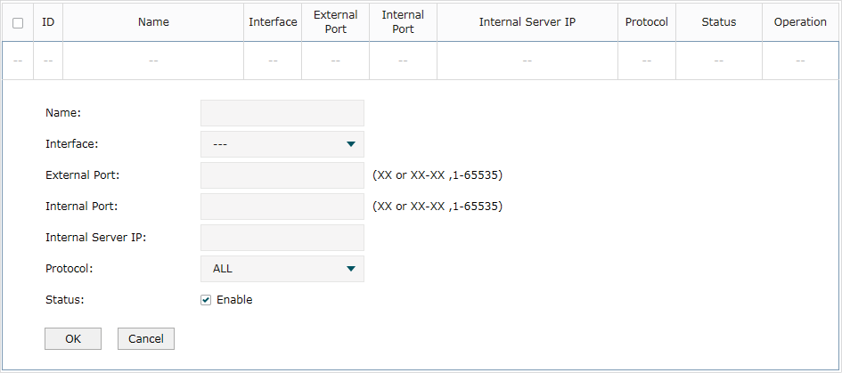
Follow these steps to configure the Virtual Servers:
1)Specify the name of the Virtual Server rule and configure other related parameters.
|
Interface |
Specify the effective interface for the rule. |
|
External Port |
Enter the service port or port range the router provided for accessing external network. The ports or port ranges cannot overlap with those of other virtual server rules. |
|
Internal Port |
Specify the service port or port range of the LAN host as virtual server. |
|
Internal Server IP |
Enter the IP address of the specified internal server for the entry. All the requests from the internet to the specified LAN port will be redirected to this host. |
|
Protocol |
Specify the protocol used for the entry. |
|
Status |
Check the box to enable the rule. |
2)Click OK.
2.4Configuring the Port Triggering
Choose the menu Transmission > NAT > Port Triggering and click Add to load the following page.
Figure 2-4 Configuring the Port Triggering
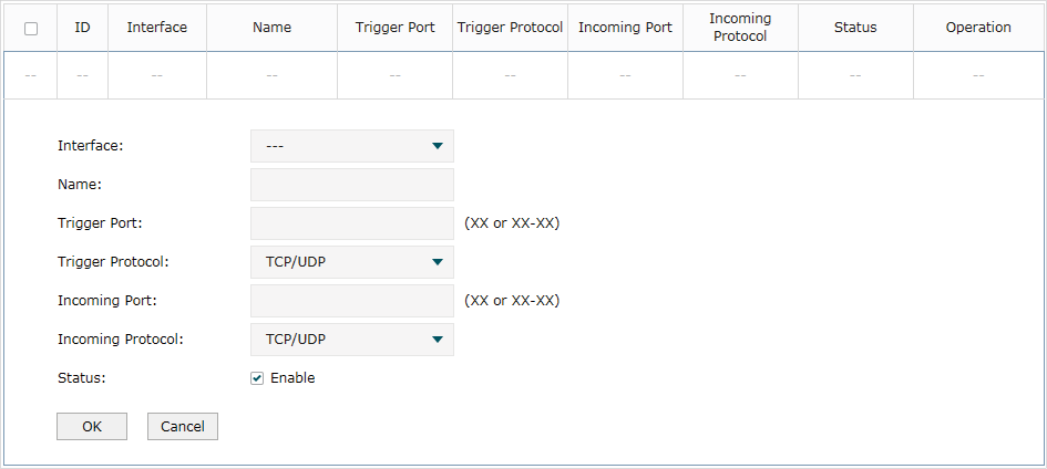
Follow these steps to configure the Port Triggering:
1)Specify the name of the Port Triggering rule and configure other related parameters.
|
Interface |
Specify the effective interface for the rule. |
|
Trigger Port |
Enter the trigger port or port range. Each entry supports at most 5 groups of trigger ports. For example, you can enter 1-2, 3-4, 5-6, 7-8, 8-9. Note that the ports or port ranges cannot overlap with those of other port triggering rules. |
|
Trigger Protocol |
Specify the trigger protocol for the trigger port. |
|
Incoming Port |
Enter the incoming port or port range. Each entry supports at most 5 groups of incoming ports. For example, you can enter 1-2, 3-4, 5-6, 7-8, 8-9. Note that the ports or port ranges cannot overlap with those of other port triggering rules. |
|
Incoming Protocol |
Specify the incoming protocol for the incoming port. |
|
Status |
Check the box to enable the rule. |
2)Click OK.
2.5Configuring the NAT-DMZ
Choose the menu Transmission > NAT > NAT-DMZ and click Add to load the following page.
Figure 2-5 Configuring the NAT-DMZ
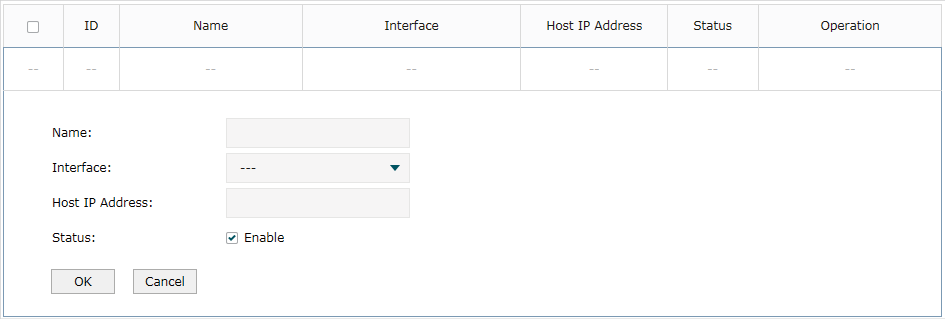
Follow these steps to configure the NAT-DMZ:
1)Specify the name of the NAT-DMZ rule and configure other related parameters.
|
Interface |
Specify the effective interface for the rule. |
|
Host IP Address |
Specify the host IP address for NAT-DMZ.. |
|
Status |
Check the box to enable the rule. |
2)Click OK.
2.6Configuring the ALG
Choose the menu Transmission > NAT > ALG to load the following page.
Figure 2-6 Configuring the ALG
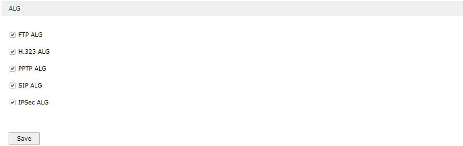
Enable related ALG according to your needs and click Save.
3Bandwidth Control Configuration
Bandwidth Control functions to control the bandwidth by configuring rules for limiting various data flows. In this way, the network bandwidth can be reasonably distributed and utilized.
Choose the menu Transmission> Bandwidth Control to load the following page.
Figure 3-1 Configuring the Bandwidth Control
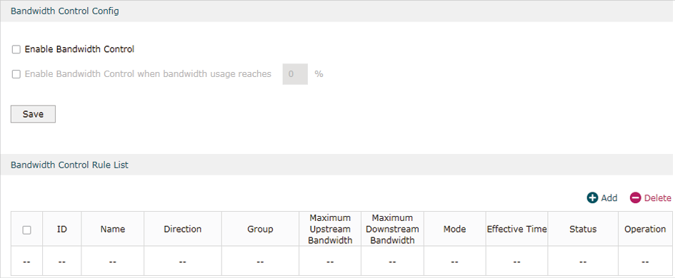
Follow these steps to configure the Bandwidth Control rule:
1)In the Bandwidth Control Config Section, enable Bandwidth Control function globally.
|
Enable Bandwidth Control |
Check the box to enable Bandwidth Control globally. |
|
Enable Bandwidth Control When |
With “Enable Bandwidth Control” selected, you can specify a percentage, and the Bandwidth Control will take effect only when the bandwidth usage reaches the percentage you specified. |
2)In the Bandwidth Control Rule List section, click Add to load the following page.
Figure 3-2 Add Bandwidth Control rules
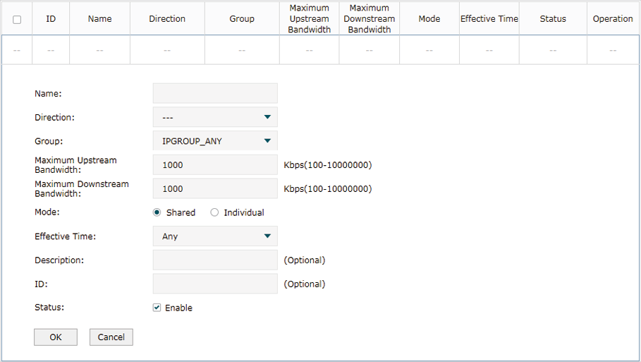
Specify the name of the Bandwidth Control rule and configure other related parameters.
Then click OK.
|
Direction |
Specify the data stream direction for the rule. |
|
Group |
Specify the address group for the rule to define the controlled users. The IP group referenced here can be created on the Preferences > IP Group > IP Group page. |
|
Maximum Upstream Bandwidth |
Specify the Maximum Upstream Bandwidth in Kbps for the rule. |
|
Maximum Downstream Bandwidth |
Specify the Maximum Downstream Bandwidth in Kbps for the rule. |
|
Mode |
Specify the bandwidth control mode for the address group. Individual means the bandwidth of each user is equal to the current bandwidth of this entry. Shared means the total bandwidth of all controlled IP addresses is equal to the current bandwidth of this entry. |
|
Effective Time |
Specify the time for the rule to take effect. Any means it always takes effect. The time range referenced here can be created on the Preference > Time Range > Time Range page. |
|
Description |
Enter a brief description for the rule. |
|
ID |
Append the rule to the right position to give a priority for the rule. |
|
Status |
Check the box to enable the rule. |
To complete Session Limit configuration, follow these steps:
1)Configure session limit.
2)View the session limit information.
4.1Configuring Session Limit
Choose the menu Transmission> Session Limit > Session Limit to load the following page.
Figure 4-1 Configuring the Session Limit
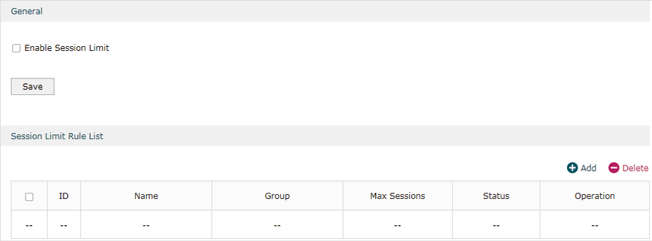
Follow these steps to configure the Session Limit rule:
1)In the General Section, enable Session Limit function globally.
2)In the Session Limit Rule List section, click Add to load the following page.
Figure 4-2 Add Session Limit rules
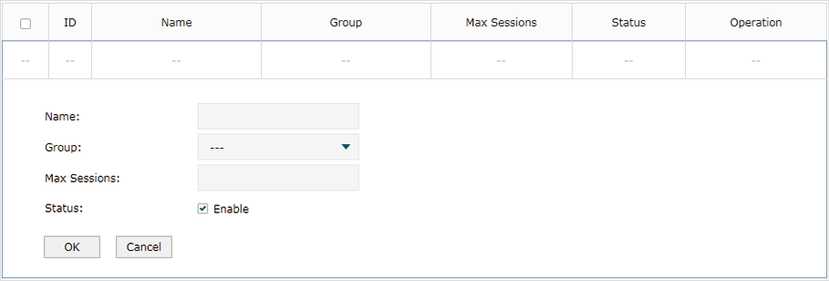
Specify the name of the Session Limit rule and configure other related parameters.
Then click OK.
|
Group |
Specify the address group to which the rule will be applied. The IP group referenced here can be created on the Preferences > IP Group > IP Group page. |
|
Max Sessions |
Specify the max sessions for the controlled users. |
|
Status |
Check the box to enable the rule. |
4.2Viewing the Session Limit Information
Choose the menu Transmission> Session Limit > Session Monitor to load the following page.
Figure 4-3 Viewing the Session Limit Information

View the Session Limit information of hosts configured with Session Limit. Click the Refresh button to get the latest information.
5Load Balancing Configurations
With load balancing configurations, you can:
Configure the load balancing
Configure the link backup
Configure the online detection
5.1Configuring the Load Balancing
Choose the menu Transmission> Load Balancing > Basic Settings to load the following page.
Figure 5-1 Configuring the Load Balancing
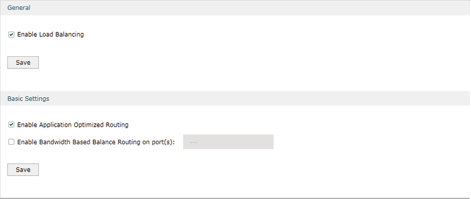
Follow these steps to configure the load balancing:
1)In the General Section, enable load balancing function globally and click Save.
2)In the Basic Settings section, select the appropriate method for load balancing and click Save.
|
Enable Application Optimized Routing |
With Application Optimized Routing enabled, the router will consider the source IP address and destination IP address (or destination port) of the packets as a whole and record the WAN port they pass through. Then the packets with the same source IP address and destination IP address (or destination port) will be forwarded to the recorded WAN port. This feature ensures that multi-connected applications work properly. |
|
Enable Bandwidth Based Balance Routing on port(s) |
Select the WAN port from the drop-down list to enable Bandwidth Based Balance Routing. |
5.2Configuring the Link Backup
With Link Backup function, the router will switch all the new sessions from dropped line automatically to another to keep an always on-line network.
Choose the menu Transmission> Load Balancing > Link Backup and click Add to load the following page.
Figure 5-2 Configuring the Link Backup Rule
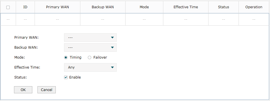
Configure the following parameters on this page and click OK.
|
Primary WAN |
Specify the primary WAN port. |
|
Backup WAN |
Specify the backup WAN port to back up the traffic for the primary WAN port under the specified condition. |
|
Mode |
Specify the mode as Timing or Failover. Timing: Link Backup will be enabled if the specified effective time is reached. All the traffic on the primary WAN will switch to the backup WAN at the beginning of the effective time; the traffic on the backup WAN will switch to the primary WAN at the ending of the effective time. Failover: Enable backup link when primary WAN failed. |
|
Effective Time |
Specify the time for the rule to take effect. Always means it always take effect. The time range referenced here can be created on the Preference > Time Range > Time Range page. |
|
Status |
Check the box to enable the rule. |
5.3Configuring the Online Detection
With Online Detection function, you can detect the online status of the WAN port.
Choose the menu Transmission> Load Balancing > Online Detection and click  to load the following page.
Figure 5-3 Configuring the Online Detection
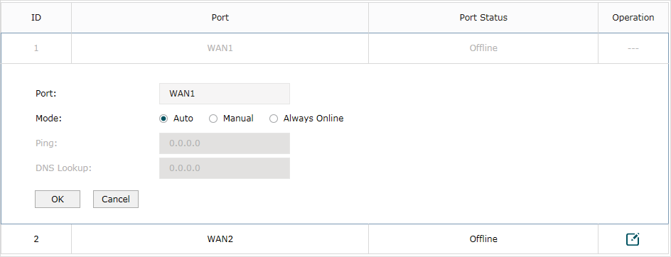
Configure the following parameters on this page and click OK.
|
Port |
Displays the name of WAN Port. |
|
Mode |
Select the online detection mode. Auto: In Auto Mode, the DNS server of the WAN port will be selected as the destination for DNS Lookup to detect whether the WAN is online. Manual: In Manual Mode, you can configure the destination IP address for PING and DNS Lookup manually to detect whether the WAN is online. Always Online: In Always Online Mode, the status of the port will always be online. |
|
Ping |
With “Manual Mode” selected, specify the destination IP for Ping. The correspoding port will ping the IP address to detect whether the WAN port is online. 0.0.0.0 means Ping detection is disabled. |
|
DNS Lookup |
With “Manual Mode” selected, specify the IP address of DNS server. The correspoding port will perform the DNS lookup using default domain name to detect whether the WAN port is online. 0.0.0.0 means DNS Lookup is disabled. |
With routing configurations, you can:
Configure the static routing
Configure the policy routing rule
View the routing table
6.1Configuring the Static Routing
Choose the menu Transmission> Routing > Static Route and click Add to load the following page.
Figure 6-1 Configuring the Static Routing
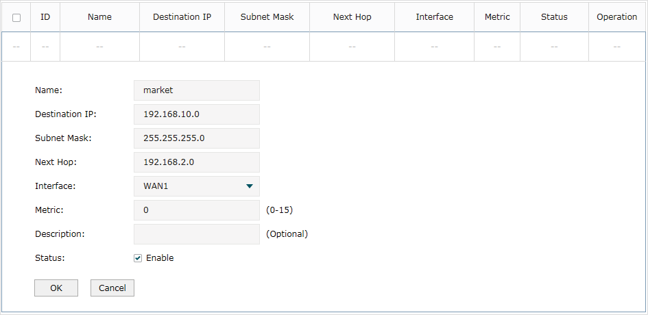
Specify the name of the static route entry and configure other related parameters. Then click OK.
|
Destination IP |
Specify the destination IP address the route leads to. |
|
Subnet Mask |
Specify the subnet mask of the destination network. |
|
Next Hop |
Specify the IP address to which the packet should be sent next. |
|
Interface |
Specify the physical network interface through which this route is accessible. |
|
Metric |
Define the priority of the route. A smaller value means a higher priority. The default value is 0. It is recommended to keep the default value. |
|
Description |
Enter a brief description for the rule. |
|
Status |
Check the box to enable the rule. |
6.2Configuring the Policy Routing
Choose the menu Transmission> Routing > Policy Routing and click Add to load the following page.
Figure 6-2 Configuring the Policy Routing
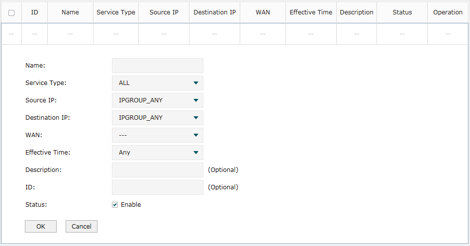
Specify the name of the policy routing entry and configure other related parameters. Then click OK.
|
Service Type |
Specify the service type for the rule. |
|
Source IP |
Enter the source IP range for the rule. 0.0.0.0 - 0.0.0.0 means any IP is acceptable. |
|
Destination IP |
Enter the destination IP range for the rule. 0.0.0.0 - 0.0.0.0 means any IP is acceptable. |
|
WAN |
Specify the outcoming port for the rule. |
|
Effective Time |
Specify the effective time for the rule. |
|
Description |
Enter a brief description for the rule. |
|
Status |
Check the box to enable the rule. |
6.3Viewing the Routing Table
Choose the menu Transmission> Routing > Routing Table to load the following page.
Figure 6-3 Routing Table
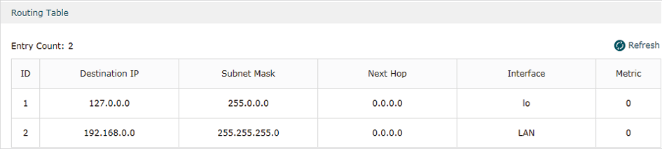
The Routing Table shows the information of the current route entries.
|
Destination IP |
Displays the destination IP address the route leads to. |
|
Subnet Mask |
Displays the subnet mask of the destination network. |
|
Next Hop |
Displays the gateway IP address to which the packet should be sent next. |
|
Interface |
Displays the physical network interface through which this route is accessible. |
|
Metric |
Displays the metric to reach the destination IP address. |
7.1Example for Configuring NAT
7.1.1Network Requirements
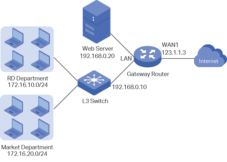
A company has two departments: Market Department and RD department. Each department is assigned to an individual subnet. The company has the following requirements:
1)The two departments need to access the internet via the same gateway router.
2)The company has a web server which needs to be accessed by the users on the internet.
7.1.2Network Topology
Figure 7-1 Network Topology
7.1.3Configuration Scheme
To meet the first requirement, add Multi-nets NAT entries for the two departments respectively on the gateway router, thus the router can translate and deliver packets whose source IP addresses are in different subnets from the router’s LAN IP segment. Then configure static routing on the gateway router to make sure the router know where to deliver the packets to IP addresses in different subnets (172.16.10.0/24, 172.16.20.0/24).
To meet the second requirement, add One-to-One NAT entry for the Web Server on the gateway router, thus the web server with a private IP address can be accessed at a corresponding valid public IP address. Note that One-to-One NAT take effects only when the connection type of WAN port is Static IP.
7.1.4Configuration Procedure
Follow the steps below to configure NAT on the gateway router:
Configuring the Multi-Nets NAT
1)Choose the menu Transmission > NAT > Multi-Nets NAT to load the configuration page, and click Add.
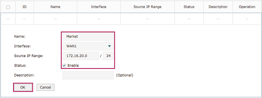
2)Add Multi-nets NAT entries for the two departments respectively: Specify the entry name as RD/Market, choose the interface as WAN1, and enter the network address of the RD/Market department as source IP range. Keep Status of this entry as Enable. Click OK.
Figure 7-2 Adding a Multi-Nets Entry for RD Department
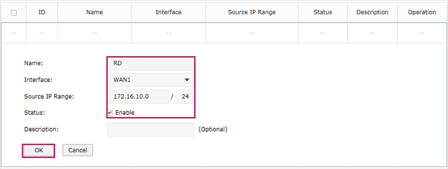
Figure 7-3 Adding a Multi-Nets Entry for Market Department
Configuring the static routing
1)Choose the menu Transmission > Routing > Static Route to load the configuration page, and click Add.
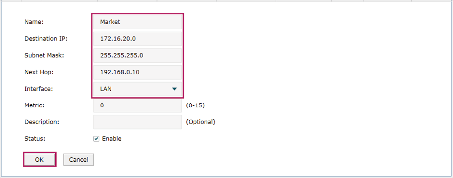
2)Add static routes for the two departments respectively: Specify the entry name as RD/Market, enter 172.16.10.0/172.16.20.0 as the destination IP, and specify the VLAN 1 interface IP of L3 switch as next hop, then choose the interface as WAN1. Keep Status of this entry as Enable. Click OK.
Figure 7-4 Configuring the Static Routing for RD Department
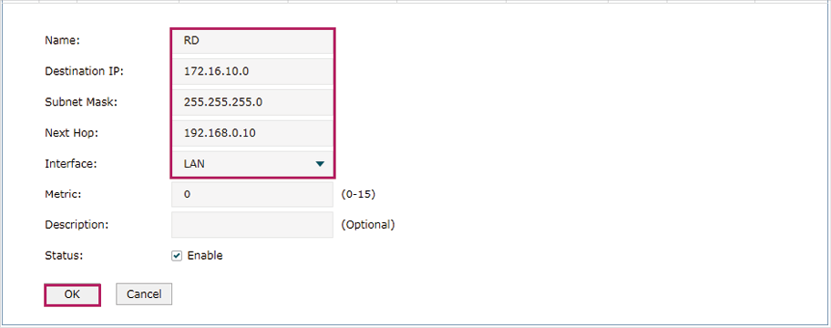
Figure 7-5 Configuring the Static Routing for Market Department
Configuring the One-to-One NAT
1)Choose the menu Transmission > NAT > One-to-One NAT to load the configuration page, and click Add.
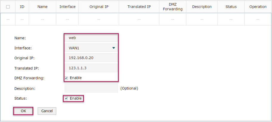
2)Add a One-to-One NAT entry for the web server: Specify the entry name as web, choose the interface as WAN1, and enter the orignal IP as 192.168.0.20, the translated IP as 123.1.1.3. Enable DMZ Forwarding, then keep Status of this entry as Enable. Click OK.
Figure 7-6 Adding a Multi-Nets Entry for RD Department
7.2Example for Configuring Load Balancing
7.2.1Network Requirements
To make good use of bandwidth, the network administrator decides to bind two WAN links using load balancing.
7.2.2Network Topology
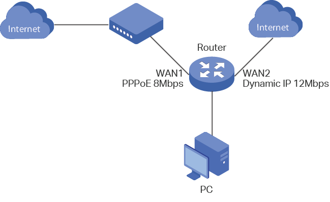
Figure 7-7 Network Topology
7.2.3Configuration Scheme
To meet the requirement, configure WAN parameters on the router in order that the two WAN links can work properly and have access to the internet, then configure load balancing on the router to aggregate two WAN links.
7.2.4Configuration Procedure
Follow the steps below to configure load balancing on the router:
Configuring the WAN parameters
For WAN1 port, configure the connection type as PPPoE, and specify Upstream and Downstream bandwidth for this link based on your ADSL bandwidth (You could consult your internet Service Provider for the bandwidth information).
For WAN2 port, configure the connection type as Dynamic IP, and specify Upstream and Downstream bandwidth for this link according to data that ISP provides.
Make sure two WAN links can work properly and have access to the internet.
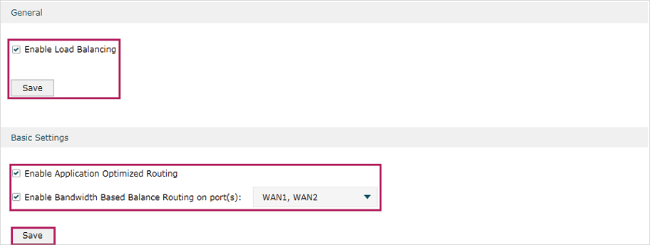
Configuring the Load Balancing
Choose the menu Transmission> Load Balancing > Basic Settings to load the configuration page. Enable Load Balancing globally, and click Save. Enable Application Optimized Routing, and enable Bandwidth Based Balancing Routing on WAN1 port and WAN2 port. Click Save.
Figure 7-8 Configuring the Load Balancing
7.3Example for Configuring Virtual Server
7.3.1Network Requirements
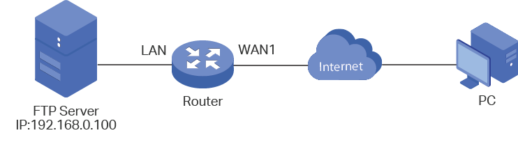
The network administrator builds up a FTP server on the local network and wants to share it on the internet.
7.3.2Network Topology
Figure 7-9 Network Topology
7.3.3Configuration Scheme
In this scenario, both virtual server and DMZ host can be configured to meet the requirement. Here we take configuring Virtual Server as an example, owing to that for a DMZ host all ports are open which may result in unsafety. Configure the FTP server as a virtual server on the router so that the FTP server can be accessed by the internet user.
Demonstrated with TL-ER6120, The following section provides the configuration procedure.
7.3.4Configuration Procedure
Follow the steps below to configure virtual server on the router:
1)Choose the menu Network > NAT > Virtual Servers to load the configuration page, and click Add.
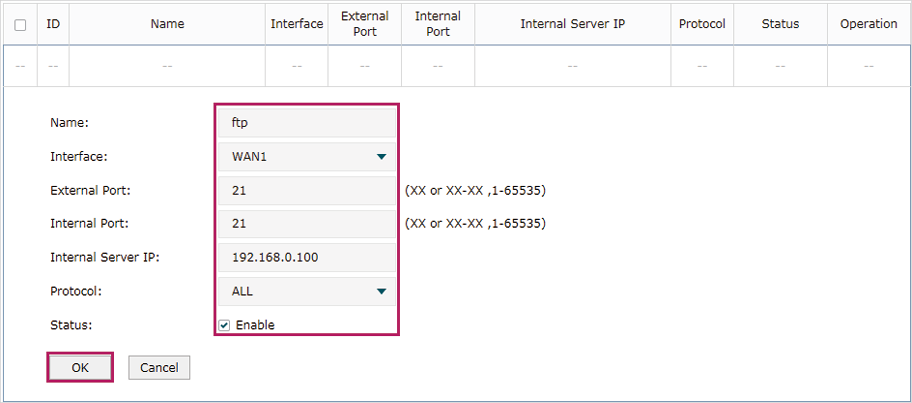
2)Specify the entry name as ftp, choose the interface as WAN1, and specify the internal/external port as 21, enter the IP address of FTP server (192.168.0.100) as the internal server IP. Select the protocol as All, then keep Status of this entry as Enable. Click OK.
Figure 7-10 Configuring the Virtual Server
7.4Example for Configuring Policy Routing
7.4.1Network Requirements
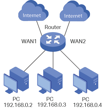
The network administrator has a router with 3 computers (192.168.0.2-192.168.0.4) connected to the LAN side, all computers are routed to internet by WAN1 port and WAN2 port, the requirements are as follows:
WAN2 link is used to backup WAN1 link to keep an always on-line network.
The two computers with IP addresses 192.168.0.2 and 192.168.0.3 are required to use WAN1 for web surfing, WAN2 for other internet activities.
7.4.1Network Topology
Figure 7-11 Network Topology
7.4.2Configuration Scheme
To meet the first requirement, configure link backup on the router. To meet the second requirement, configure policy routing rules for two computers which use 192.168.0.2 and 192.168.0.3. Note that link backup rule has a higher priority than policy routing rule.
7.4.3Configuration Procedure
Follow the steps below to configure link backup and policy routing on the router:
Configuring the Link Backup
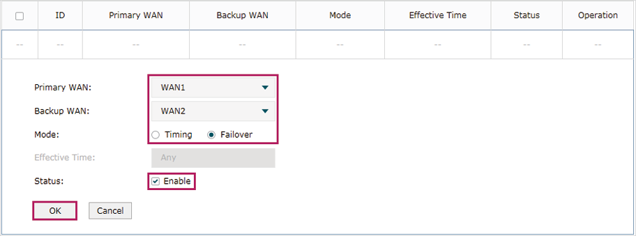
1)Choose the menu Transmission > Load Balancing > Link Backup to load the configuration page, and click Add.
2)Specify the primary WAN as WAN1, the backup WAN as WAN2 and the mode as Failover so that the backup link will be enabled when the primary WAN failed. Keep Status of this entry as Enable. Click OK.
Figure 7-12 Configuring the Link Backup
Configuring the Policy Routing Rules
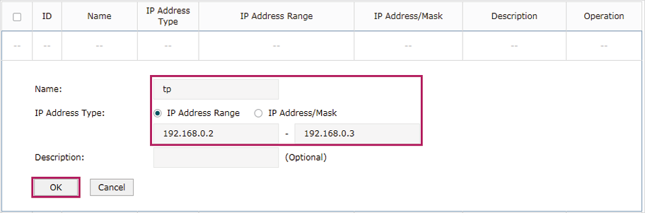
1)Choose the menu Preferences > IP Group > IP Address to load the configuration page, and click Add. Specify the IP address name as tp, the IP address type as IP Address Range (192.168.0.2-192.168.0.3). Click OK.
Figure 7-13 Configuring the IP Address
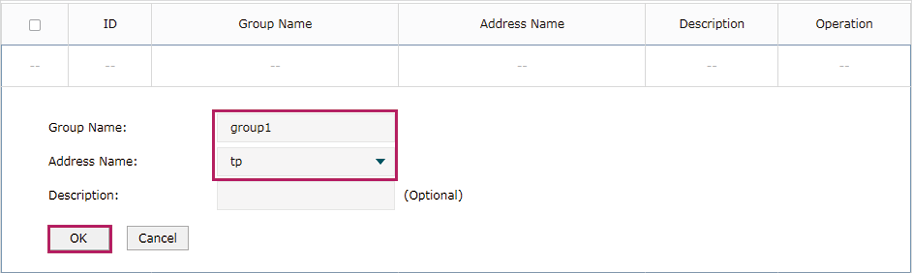
2)Choose the menu Preferences > IP Group > IP Address to load the configuration page and click Add. Specify the IP group name as group1, the IP address name as tp to reference the IP address you have created. Click OK.
Figure 7-14 Configuring the IP Group
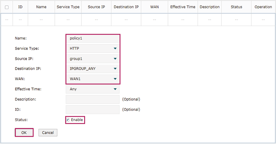
3)Choose the menu Transmission > Routing > Policy routing to load the configuration page, and click Add.
Specify the policy routing rule name as policy1, the service type as HTTP, the source IP as group1, the destination IP as IPGROUP_ANY which means no limit. Choose WAN1, and keep Status of this entry as Enable. Click OK.
Figure 7-15 Configuring the Policy Routing Rule 1
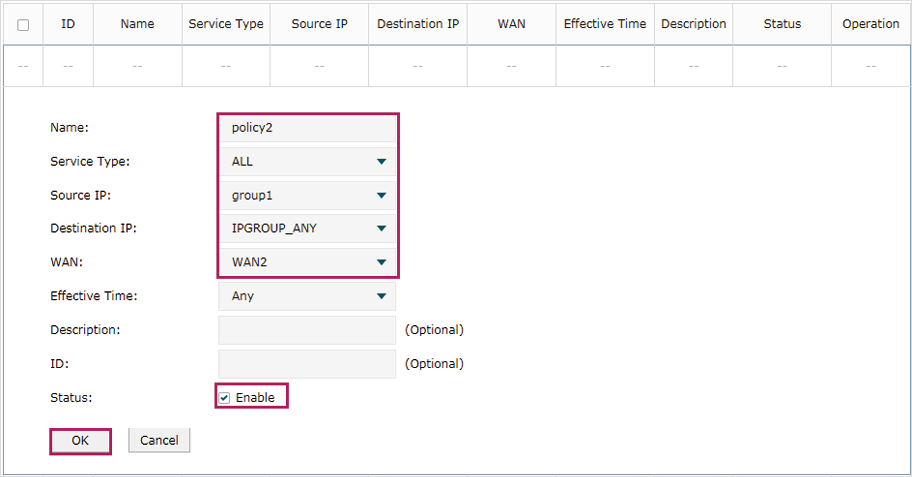
Specify the policy routing rule name as policy2, the service type as ALL, the source IP as group1, the destination IP as IPGROUP_ANY which means no limit. Choose WAN2, and keep Status of this entry as Enable. Click OK.
Figure 7-16 Configuring the Policy Routing Rule 2